background image

III. Safety 

Instructions 


Always read the Safety Instructions carefully. 


  Keep this user’s manual for future reference. 

  Keep this equipment away from humidity. 

  Lay this equipment on a reliable flat surface before setting it up. 

  If any of the following situations arises, get the equipment checked 

by a service technician: 

  The equipment has been exposed to moisture. 

  The equipment has been dropped and damaged. 

  The equipment has obvious sign of breakage.


  The equipment is not working well.


  If you cannot get it to work according to this User’s Manual 

refer to the Warranty in Section XI.


 5 

Summary of Contents for HO97916

Page 1: ...HO97916 USB 2 0 7 Port Hub I IN NS ST TR RU UC CT TI IO ON N M MA AN NU UA AL L www jascoproducts com ...

Page 2: ...OVERVIEW 4 III SAFETY INSTRUCTIONS 5 IV POWER MODE SETTING 6 V SOFTWARE INSTALLATION VI HUB STAND ASSEMBLY 7 VII HARDWARE INSTALLATION 13 VIII TROUBLESHOOTING 16 IX TECHNICAL SPECIFICATIONS 17 X FCC COMPLIANCE STATEMENT 18 XI WARRANTY 19 15 ...

Page 3: ...ew USB 2 0 7 Port Hub and follow the instructions to prevent damage to the USB 2 0 7 Port Hub and or the connecting devices THIS PACKAGE INCLUDES USB 2 0 7 Port Hub USB 2 0 Device Cable 6 feet AC DC Power Adapter User s Manual Two Magnets Two metal magnet holders Two screws 3 ...

Page 4: ...t is compatible with all USB 1 1 and 2 0 devices You can stack multiple hubs together to support up to 127 devices through a single USB port on your computer FEATURES USB 1 1 and 2 0 compatible Stackable and Mountable via magnets or screws Connect up to 5 high powered devices at once 1 LED to indicate power 7 LEDS to indicate individual port activity Plug and Play Bus fault detection and recovery ...

Page 5: ... flat surface before setting it up If any of the following situations arises get the equipment checked by a service technician The equipment has been exposed to moisture The equipment has been dropped and damaged The equipment has obvious sign of breakage The equipment is not working well If you cannot get it to work according to this User s Manual refer to the Warranty in Section XI 5 ...

Page 6: ... will notice a decrease in performance An additional hub is considered a high powered device The second is bus power mode which does NOT require the use of the AC power adapter In this mode the hub is provided with 500 milliamps for all 7 ports This should be adequate for mice keyboards and other low power devices If you are not sure or if device performance is poor use the AC adapter When using t...

Page 7: ...crews Hub may be oriented vertically or horizontally Hubs may be stacked Contents the hub to your desk If you choose this mounting method you will need to purchase the two screws separately Stand Magnets Screws 7 Note Package does not include the two screws needed to mount ...

Page 8: ...ten the magnet to the stand as shown in the diagram 3 Follow the directions in Sections C D to attach the hub to the stand 4 Attach the stand with the hub to your desk or other flat metal location Note To eliminate data loss do not place disks near the magnets Screw Screw Magnet Metal Magnet Holder Magnet Metal Magnet Holder Bottom of Stand 8 ...

Page 9: ...e are not provided 2 Place the stand where you would like it secured to your desk 3 Fasten the screws in the screw holes on both sides of the stand 4 Attach the hub as described in Sections C D Note You will need to purchase the two screws separately These are not provided Desk Screws 9 ...

Page 10: ... Attach Hub to Stand Vertically 1 Line up the tracks of either side of the hub with the rails on the stand 2 Slide the hub all the way back on the stand until you hear a click Rails Hub Clips Push Hub 10 ...

Page 11: ...D Attach Hub to Stand Horizontally 1 Line up the hooks on the bottom of the hub with the hub clips on the stand 2 Slide the hub onto the stand until you hear a click Hub Clips Push Hub 11 ...

Page 12: ...E Stacking Hubs 1 Face the Hubs in the same direction 2 Line up the hooks on the bottom of Hub A with the top cover of Hub B 3 Slide Hub A onto Hub B as shown in the diagram Hub A Hub B 12 ...

Page 13: ...are Installation 1 Make sure your computer has all the necessary updates required to support USB 2 0 These can be found on Microsoft s website 2 Position the Hub as desired using the directions in Section VI 13 ...

Page 14: ...ed to use the ac power adapter 5 Plug the B type connector of the included USB 2 0 device cable into the Upstream Port on the rear of the USB 2 0 7 Port Hub 6 Plug the A type connector of the included USB 2 0 device cable into the USB port of your computer or into another USB hub 7 Connect your USB devices to any of the 7 available Downstream Ports If properly connected the corresponding green Por...

Page 15: ... automatically run the Add New Hardware Wizard 2 When the initial screen appears introducing the Add New Hardware Wizard click Next 3 Select Search for the best driver for your device Recommended and click Next 4 When asked to select a location to search for the drivers use the default selection Do not change the location Click Next 5 Click Next to accept the location the driver will be installed ...

Page 16: ... laptop USB 2 0 Hubs may not work on all laptops Try the hub on a desktop computer to confirm functionality of the hub If this works contact your computer dealer Hub Not Seen on Windows 98 or 98 SE If you plugged the camera in prior to installing the software with Windows 98 or 98 SE your computer needs to be shown where the USB driver is Please contact customer service 16 ...

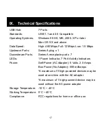
Page 17: ...wnstream Ports Series A receptacle port x 7 LEDs 1 Power Indicator 7 Port Activity Indicators Power Self Power AC Adapter 5 Volts 2 5 Amps Bus Power No Adapter 500 milliamps A maximum of 5 high powered devices may be used at one time with the AC adapter A maximum of 1 high powered device may be used without the AC power adapter Storage Temperature 10 C 40 C Working Temperature 0 C 40 C Compliance ...

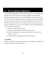
Page 18: ...re is no guarantee that interference will not occur in television reception which can be determined by turning the equipment off and on the user is encouraged to try and correct the interference by one or more of the following measures 1 Reorient or relocate the receiving antenna 2 Increase the separation between the equipment and the receiver 3 Connect the equipment into an outlet on a circuit di...

Page 19: ... implied Some states do not allow limitations on how long an implied warranty lasts or permit the exclusion or limitation of incidental or consequential damages so the above limitations may not apply to you This warranty gives you specific rights and you may also have other rights which vary from state to state If unit should prove defective within the warranty period return prepaid with dated pro...

Reviews: