14
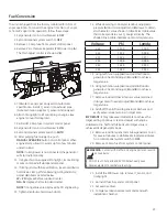
When the initial test runs are completed, the manometer
is removed and the port is plugged. A typical final fuel
connection assembly is shown here, where (a) is the fuel
supply and (B) goes to the home generator.
It is recommended that the fuel connection incorporate the
following components:
• A minimum 10 ft. (3 m) section of gas pipe between
the primary fuel regulator and the generator fuel inlet
connection (acts as accumulator for high block loads).
• A manual fuel shut-off valve located in the interior of
the building.
• A manual fuel shut-off valve located outside the
building, just before the generator unit.
• Where the formation of hydrates or ice is known to
occur, piping should be protected against freezing.
The termination of hard piping should include
a sediment trap where condensate is not likely
to freeze.
• A manometer port should be provided.
The manometer port permits temporary installation of
a manometer to ensure that the engine receives the
correct fuel pressure to operate efficiently throughout its
operating range.
fuel Pipe sizing
There are numerous on-line or otherwise-published
references for fuel pipe sizing. For example, NFPA 54 -
National Fuel Gas Code, 2006 (Item #: 320-6031-06) is a
common resource. The installer should consider the specific
gravity of gas and compensate for a nominal amount of
restriction from bends, fittings, etc. If an unusual number of
fittings, bends, or other restrictions are used, refer to federal
and local codes for guidance.
A
B
Summary of Contents for HOME NERATOR SYSTEM 27000-30000 WATT -
Page 24: ...24 Schematic Diagram ...
Page 25: ...25 Wiring Diagram ...


