15
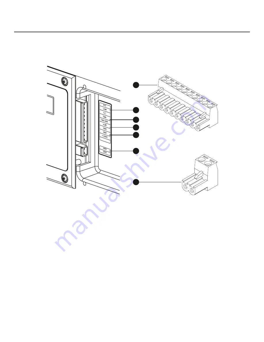
Low Voltage connections to signal fault contacts, transfer switch communication, remote LED and auxiliary 12VDC
power are made via a removable ten-pin connector plug.
Compare this illustration with your generator to familiarize yourself with the location of these connections:
count down
to the proper pin location on the control board because visual alignment with the decal can be misleading.
system connectors
a – ten-pin connector Plug
B - fault contacts
— Use NO, COM and NC to hook up a
siren, light, etc. to alert you in case of a fault. Contacts
reverse state (NO goes to NC and vice versa) upon a
fault condition.
c - transfer switch communication
— Connect to transfer
switch control board for communication interface using
18AWG copper twisted pair wire.
D - remote LeD output (optional)
— Use this to hook up the
remote LED supplied with the generator. The remote LED
will turn on and off in a series of blinks if certain faults are
detected in the generator.
e - +12 Volt Dc, .5 amp output
— Internal auxiliary
power supply.
f - 240 Volt utility
— Use to hook up the 240V utility leads
from the transfer switch to the generator.
G – two-pin connector Plug
• For 15kW power output connection, use #6 AWG minimum 300 volt 75°C-90°C copper wire
• For 20kW power output connection, use #4 AWG minimum 300 volt 75°C-90°C copper wire
• For Utility Circuit connection use #14 AWG minimum 300 volt 75°C-90°C copper wire
• For transfer switch communication use #18 AWG twisted pair conductors, no greater than 200 ft in length, 300 volt
75°C-90°C copper wire
• When connecting to the connector plugs, fasten only one wire to each connector screw.
• Torque connector plug screws to 7 in-lb (7.9 Newton meter).
C
E
D
A
B
F
G
Not
for
Reproduction


