GEK-34054
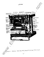
Adjust the drag magnet to obtain a c losing time as near as
possib l e to 1.31 seconds, but at least between 1.24 and 1.38 seconds.
The magnet should be approximately in the middle o f its travel.
The
magnet is adjusted by loosening the nut under the magnet she l f.
Moving the magnet in decreases the time.
Moving the magnet out
increases the t i me.
When adjusting the drag magnet, be sure the outer edge o f the
magnet never extends out beyond the cutout in the disk.
Be sure the
screw clamping the drag magnet to its supporting she l f is tight
bef ore proceeding with other time checks.
Make sure the drag magnet
does not hit the counterweight at any position o f the disk.
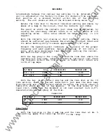
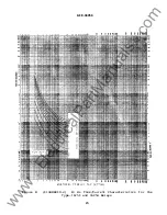
With the tap p lug in the 2amp tap and the time dial at the No. 5
time setting, check contact c losing at 2 and 10 times tap value.
These c losing times must be within the limits shown on Tabl e XV.
TABLE XV
60HZ
TAP
AMPS
MIN .SEC.
MAX. SEC.
MIN. SEC.
2.0
4.0
6.70
7. 71
6.94
2.0
20.0
0.67
0.77
0.65
INSTANTANEOUS UNIT
1.
Both contacts should close at the same time.
50HZ
MAX. SEC.
7.98
0.75
2.
The backing strip shou l d be so formed that the f orked end (front )
bears against the mol ded strip under the armature.
3.
With the armature against the pole piece, the cross member o f the
"T"
spring should
be
in a horizontal
plane and there shou l d be at
least l/32 inch wipe on the contacts.
Check this by inserting a
0.012 inch feeler gage between the front hal f o f the shaded pole
and the armature, with the armature hel d closed.
The contacts
should close with the fee ler gage in place.
TARGET AND SEAL-IN UNIT
Check steps 1 and 2 as described under INSTANTANEOUS UNIT above.
To check the wipe of the seal-in unit, insert a 0.012 inch feeler
gage between the plastic residual o f the armature and the pole
piece
with the armature held closed.
The contacts shoul d close with the
feeler gage in place.
18
www
. ElectricalPartManuals
. com


