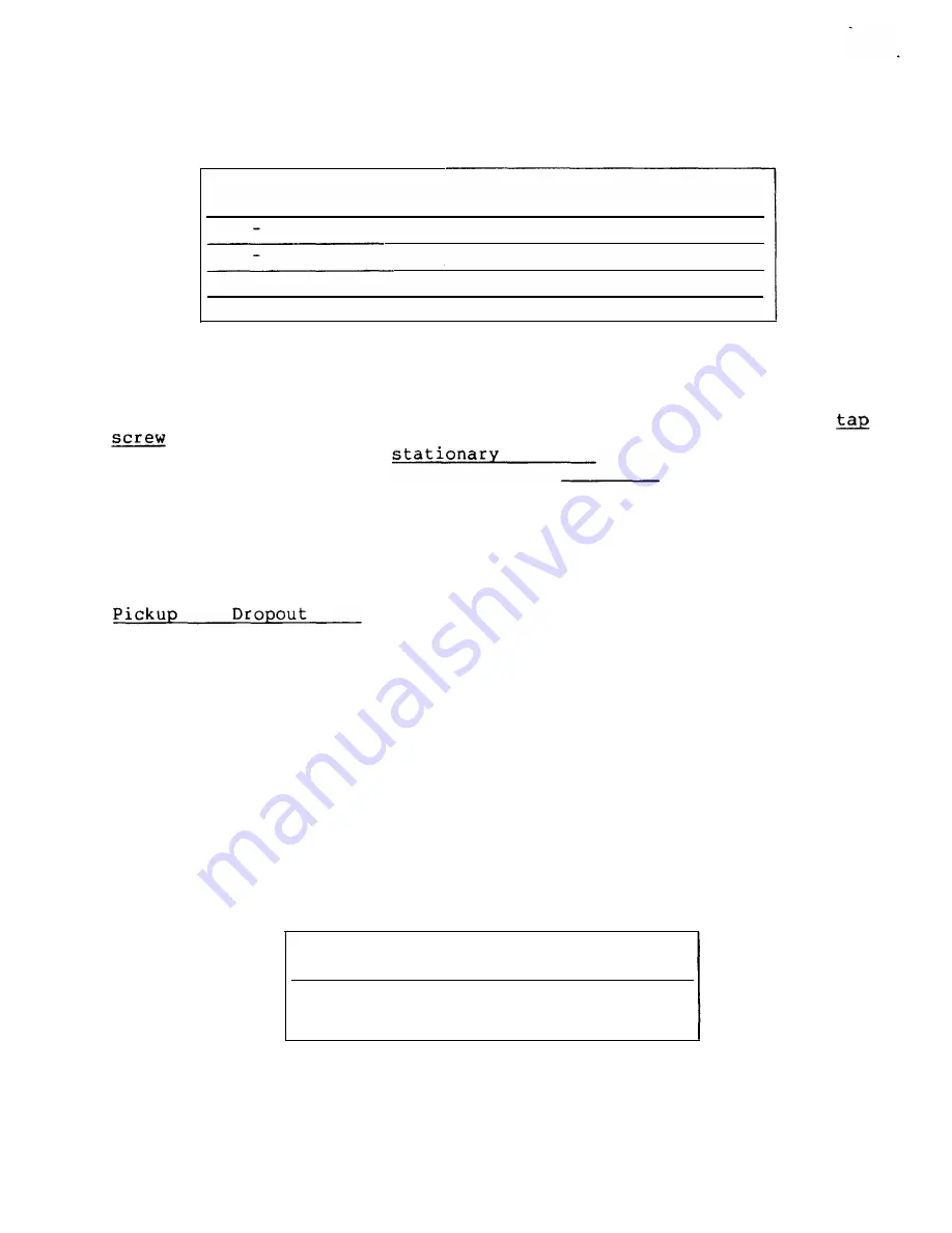
UNIT RANGE
MINIMUM
AMPERES
AMPERES
0. 5
4. 0
3. 6
2. 0
16. 0
14. 4
10. 0
-
80. 0
72. 0
20. 0
-
160.0
144. 0
TARGET AND SEAL- IN UNIT
GEK-34054
TABLE XI
CALIBRATION
AMPERES
4. 0
16. 0
80. 0
160. 0
MAXIMUM
AMPERES
4. 5
17. 7
89. 0
177 . 0
T h e t a r g et and s ea l- i n uni t h a s an oper a t i ng coil t a pped a t 0 . 2
and 2. 0 a mper es .
The r elay i s s hipped f r om t h e f a ct or y wi t h t h e
in t h e lower -amper e pos it i on .
The t a p s cr ew is t h e s cr ew
h oldi ng
t h e r i gh t -hand
con ta ct .
T o cha n g e t h e t a p
s et t i ng , f i r s t r emove one s cr ew f r om t h e lef t hand s t a t i ona r y con t act
a n d pla ce it in the des ir ed tap.
Nex t r emove t h e s cr ew f r om t h e
u n des ired t a p a n d pla ce i t on t h e left hand s t a t i ona r y con t a ct wher e
t h e fir s t s cr ew was r emoved.
See Fig u r e 2.
Th i s pr ocedu r e i s
neces sa r y t o pr even t t h e ri g h t -hand s t a t i ona r y con t act f r om g et t i ng
ou t of a djus t men t .
Scr ews shou ld
never
be lef t in
both
t a ps a t t h e
s a me t ime.
and
Tes t
1.
C onn ect r elay s tu ds
1
and 2 (See Fig u r e 14)
t o a DC s ou r ce,
a mmet er a n d load box so t h a t t h e cu r r en t can be con t r olled over a
r a ng e of 0 . 1 t o 2. 0 amperes.
2.
Tu r n the t i me dia l to the ZERO (0 ) TIME- DIAL Pos it i on .
3.
In cr ea s e t h e cu r r en t s lowl� un t il t h e s eal- in u n i t pi cks u p.
See
Table XII.
4.
Move t h e t i me dial a wa y fr om t h e ZERO T IME-DIAL P os i t i on ; t h e
s ea l-i n un i t s hould remain i n t h e pi cked-up pos i t i on.
5.
Decr ea s e t h e cu r ren t s lowly unt i l t h e s ea l- i n un i t dr ops ou t .
See Table XII.
TAP
0.2
2. 0
TABLE XII
PICK-UP
CURRENT
0. 14 - 0. 195
1. 40 - 1. 95
14
DROPOUT
CURRENT
0. 05 OR MORE
0.50 OR MORE
www
. ElectricalPartManuals
. com


