W e l c o m e
Getting Started
GFK-2357A
6" QuickPanel View Keypad
5
For complete integrity to ATEX it is recommended that the minimum panel
thickness be 0.1" (2.54mm).
■
For adequate ventilation, allow at least 3 inches of space between adjacent
equipment and all sides of the QuickPanel. Ensure that specified conditions of
temperature and humidity are not exceeded.
■
To avoid gasket degradation, limit repeated insertions or removals of the unit
and retightening of the mounting clips. For full protection, always use a fresh
gasket. Replacement gaskets may be ordered using part number
IC754ACC12GAS.
■
In outdoor applications, direct sun exposure may impose increased thermal
loads on the QuickPanel leading to excessive temperature rises. Cabinet design
and orientation must be carefully considered to avoid exceeding the
operational temperature limits. These considerations could include shading for
the QuickPanel and its cabinet with awnings or other solar opaque materials,
avoiding a due East or West facing of the cabinet, ventilation or active cooling
of the cabinet, or other methods.
The unit will
not
fit through this cutout with a CF card inserted in the port, with any
cables connected, or with the power supply plug inserted in the socket.
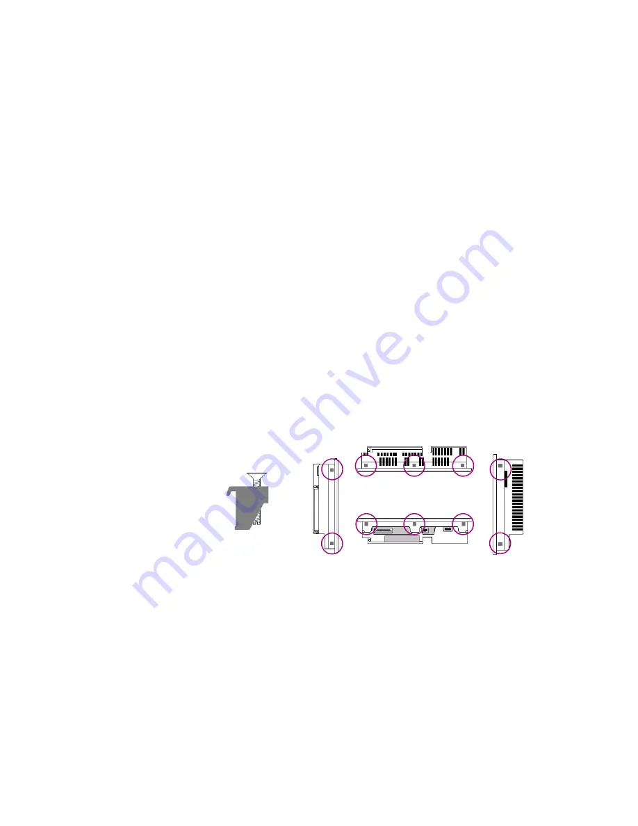
To secure the QuickPanel View Keypad to a panel, use the 10 included mounting
clamps. They hook into openings located on the top, bottom, and sides of the
housing.
To mo unt the Qu ickPanel View Key pad in a panel
1. Insert the unit into the panel cutout (without a CF card in the CF port).
2. Insert the hook of each mounting clamp into the housing openings as shown below.
3. Ensure that the gasket is properly seated in the bezel channel and firmly tighten the clamp screws.
Note:
The torque range for the mounting clamp screws is 2.6-4.4 inch/lbs
(0.3-0.5 Nm).
Top
Bottom
x 10
Right
Left
Summary of Contents for IC754VGI06SKD
Page 4: ......
Page 15: ...GFK 2357A 6 QuickPanel View Keypad 7 We l c o me Getting Started ...
Page 16: ......
Page 34: ......
Page 68: ......


