


FP1500 Installation, Configuration and Commissioning Manual
37
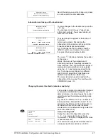
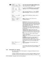
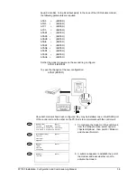
1<Options>
:
•
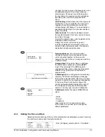
Serial port: select the port where the
modem is connected.
•
Activate modem: [NO]
•
Activate SMS: [YES]
•
PIN code: introduce the PIN number of
the GSM SIM card.
•
Fault Maximum: this option enables the
selection of the maximum number of
alerts produced by faults.
[GSM] [#Exit]
1.
Options
2. Status
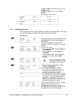
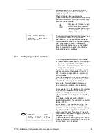
4. Once the data has been introduced, exit the
menu
[Options]
and enter
[Status]
. If the
modem has been installed correctly, a
screen should appear with the information
of the telephone operator and the available
coverage. If the coverage is not correct,
change the position of the modem.
Serial Port
[ ]
Fault Max.: [ ]
Activate MODEM: [ ]
SMS messages:
[ ]
Telephone PIN:
[ 0000 ]
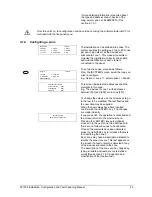
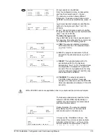
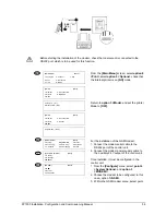
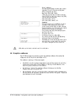
5. You now need to configure the telephones
to which the modem is to send the short
messages. The control unit differentiates
two phone numbers: one for
alarms
and
one for
faults
.
[MODEM] [#Exit]
1. GSM
2. Normal
3. Telephones
To set up the telephone numbers, from the
modem menu, select
option 3
<Telephones>
.
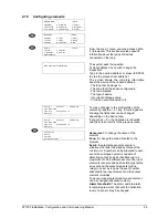
[TELEPHONES] [#Exit]
1. Faults
2. Alarms
Fault telephone
[ ]
[Upper case letters and numbers]
In
option 1 <Faults>
allocate the telephone
number to be alerted in the case of faults
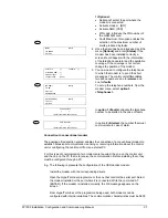
Alarm telephone
[ ]
[Upper case letters and numbers]
In
option
2 <Alarms>
the number that must
communicate in case of alarm.
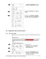
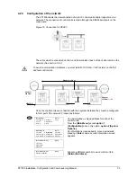
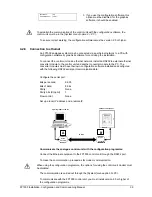
Connection to conventional modem
The analogue fire detection system enables the connection of a conventional modem to
establish occasional communication: sending or receiving information about the control
unit or configuring the control unit from an external PC.
For this type of communication, two modems are required: the one on the control unit
and the one on the PC that is to receive the communication. Before installing them, they
must be configured through a PC:
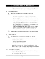
E.g. The following represents the configuration of the US Robotics modem:
Install the modem with the corresponding drivers.
Open the HyperTerminal programme or the one that controls the serial port. Select
the modem installed or the port where it is connected. Write the command AT
(ENTER). If the modem is installed correctly, the OK message appears on the
screen.
From HyperTerminal, or the programme being used, both modems can be
configured with internal variables. The communication characteristics must be 9600
1
3
2


