


FP1500 Installation, Configuration and Commissioning Manual
39
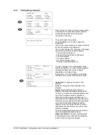
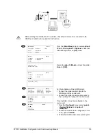
[Serial Port:
[01]
Activate Modem: [YES]
3. If you use the configuration software, this
option must be disabled, for the graphics
software, it should be enabled.
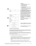
To establish the communication of the control unit with the configuration software, the
control unit must be in the [System menu] option 9 < PC >
To ensure correct working, the configuration software must be version 2.0 or higher.
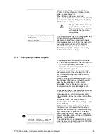
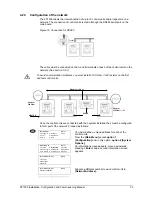
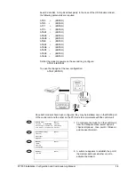
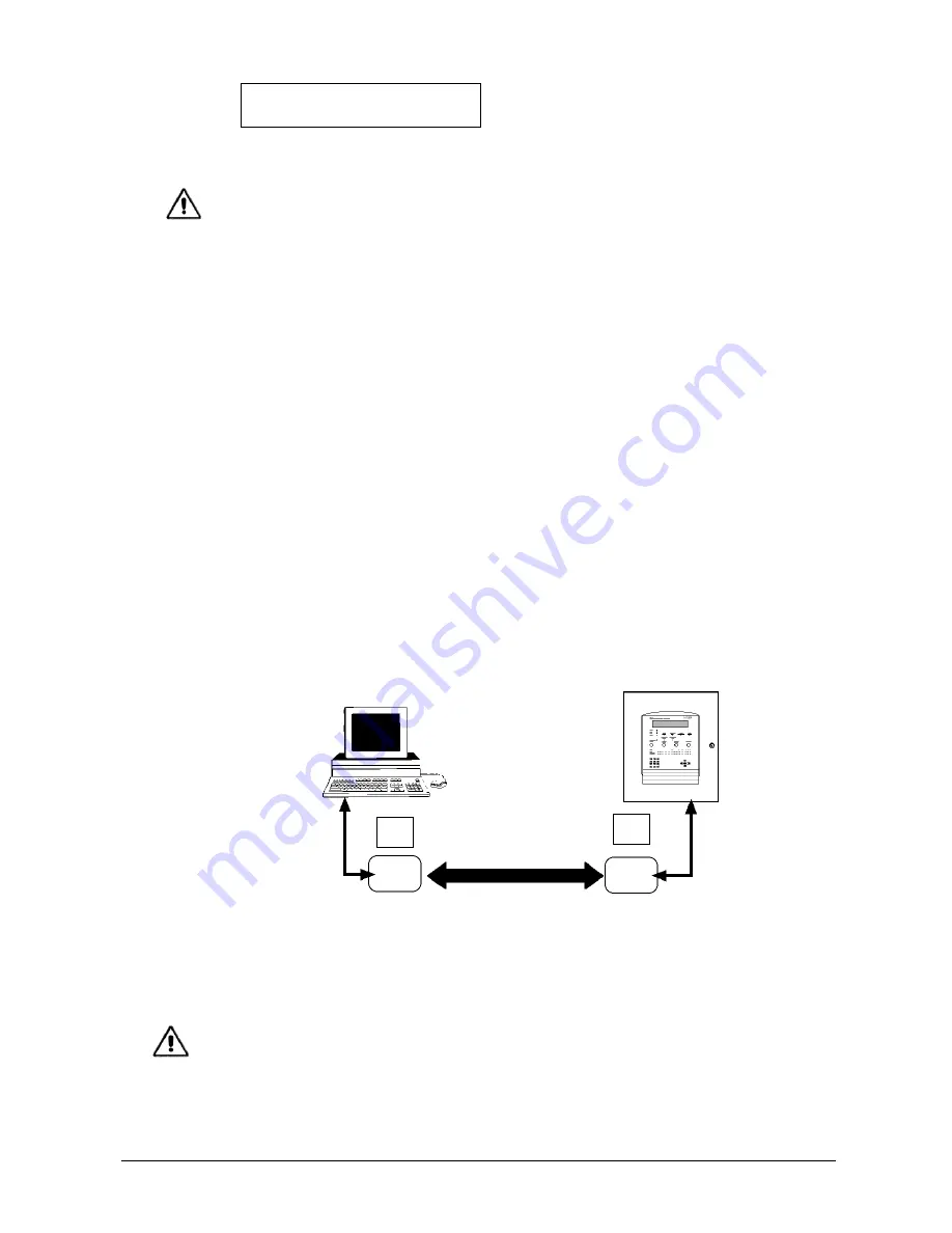
4.2.6 Connection to ethernet
An FP1500 analogue system may be connected via an ethernet network to a PC with
configuration software or graphics software for controlling the installation.
To connect the control unit on an ethernet network, install an RS232 to external ethernet
converter module to the control unit and another converter module to the PC. The
converter modules must have their own configuration software installed and configured
with the following RS232 serial port communication data:
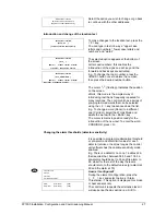
Configure the serial port:
Bits per second:
9 600
Bits of data:
8 bits
Parity: None
Parity bits (Stop bit):
1
Flow control:
None
Set up a local IP address and a remote IP.
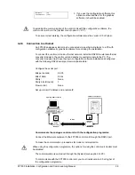
Communicate the analogue control unit with the configuration programme:
Connect the Ethernet equipment to the FP1500 control unit through the RS232 port.
To make the communication, proceed as for modem communication.
When using the configuration programme, the options for using the control unit modem must
be disabled.
The communication is carried out through the [System] menu option 9 <PC>
To communicate with the FP1500 control unit, you must install version 2.0 or higher of
the configuration programme.
PC with graphic software
FP1500 control panel
RS232
RS232
Ethernet
Module
Ethernet
Module
A
B
IP NET
Local IP:
Remote IP
Local IP:
Remote


