


Publication No. IPN250RTM-HRM/2
Connectors 25
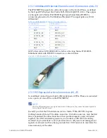
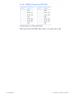
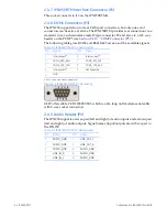
2.4.10 COM2 Connector (P5)
LINK
See also
Section 2.4.8 "COM1 Connector (P3)"
The
following
table
gives
RS232
and
RS422/485
versions
of
the
available
signals.
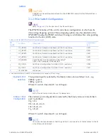
Table 2-4 IPN250RTMB P5 Pin Assignments
Pin
Signal
Pin
Signal
1
Interconnect
a
a. Pins 1, 7, and 8 are connected together.
2
Unconnected
3
COM2_RXD_RXN
4
COM2_CTS_RXP
5
COM2_TXD_TXN
6
COM2_RTS_TXP
7
Interconnect
a
8
Interconnect
a
9
GND
10
Unconnected


