O wire to the O terminal and do not connect the B wire to the B terminal (see
“Wire reference chart” on page 16 under Trane for B wire terminal).
2. Connect the Y wire to the Y terminal. This connects the compressor.
3. Connect the R wire to the RH terminal. This connects the power.
4. Connect the G wire to the G terminal. This connects the fan.
5. Set the HVAC Type switch to HP (heat pump) and set the Heat Type switch
to ELEC.
Your HVAC system is now connected to the thermostat.
Figure 13: Four-wire heat pump without AUX heat
C B O W W2 Y Y2 RH RC G A
Thermostat
Heat pump system
O
G
C
Y
R
B
or
or
Power
Five-wire heat pump with AUX heat (C, B or O, W2, Y, RH, G):
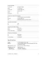
1. Connect the O wire to the O terminal or the B wire to the B terminal. This
connects the change-over valve. If you have both O and B, connect only the
O wire to the O terminal and do not connect the B wire to the B terminal (see
“Wire reference chart” on page 16 under Trane for B wire terminal).
2. Connect the W2 wire to the W2 terminal. This connects the AUX heat.
3. Connect the Y wire to the Y terminal. This connects the compressor.
4. Connect the R wire to the RH terminal. This connects the power.
5. Connect the G wire to the G terminal. This connects the fan.
6. Set the HVAC Type switch to HP (heat pump) and:
If you have gas or oil AUX heat, set the Heat Type switch to GAS.
If you have electric AUX heat, set the Heat Type switch to ELEC.
Your HVAC system is now connected to the thermostat.
14
IS-ZW-TSTAT-300 Advanced Thermostat Installation Guide


