background image

g

GE Industrial Systems

Auxiliary Drive to ISBus Interface Board

IS200ADIIH_A_ _

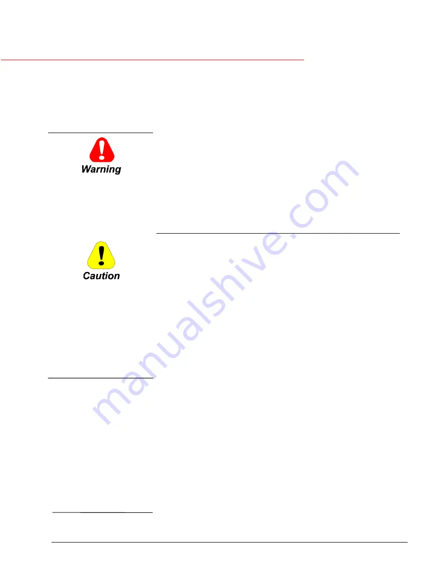
Safety Symbol Legend

Indicates a procedure or
condition that, if not strictly
observed, could result in
personal injury or death.

These instructions do not purport to cover all details or variations in equipment, nor to
provide every possible contingency to be met during installation, operation, and
maintenance. If further information is desired or if particular problems arise that are not
covered sufficiently for the purchaser’s purpose, the matter should be referred to GE
Industrial Systems.

This document contains proprietary information of General Electric Company, USA, and is
furnished to its customer solely to assist that customer in the installation, testing,
operation, and/or maintenance of the equipment described. This document shall not be
reproduced in whole or in part, nor shall its contents be disclosed to any third party
without the written approval of GE Industrial Systems.

Indicates a procedure or
condition that, if not strictly
observed, could result in damage
to or destruction of equipment.

Note


Indicates an essential or

important procedure or
statement.

Section

Page

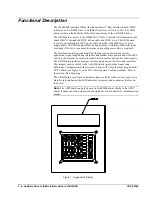
Functional Description............................................................................................ 2

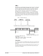
ISBus ............................................................................................................... 3

Connections ................................................................................................ 3
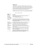
Performance ................................................................................................ 4
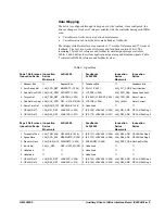
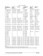
Data Mapping.............................................................................................. 5

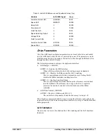
Drive Parameters ............................................................................................. 7

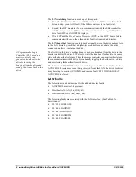
LAN Validation .......................................................................................... 7
LAN Faults ................................................................................................. 8

Application Data ..................................................................................................... 9

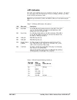
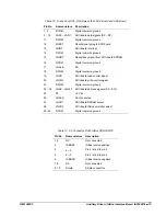
LED Indicators............................................................................................... 11
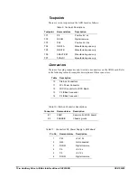
Testpoints....................................................................................................... 12
Connectors ..................................................................................................... 12

Installation and Renewal/Warranty Replacement ................................................. 14

How to Order a Board.................................................................................... 14

Board Identification .................................................................................. 14
Warranty Terms ........................................................................................ 15
Placing the Order ...................................................................................... 15

Handling Precautions..................................................................................... 15
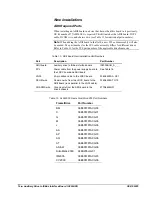
New Installations ........................................................................................... 16

ADII Required Parts ................................................................................. 16
Installation Procedures.............................................................................. 17

Replacement Procedures................................................................................ 18

Innovation Series is a trademark of General Electric Company, USA

GEI-100305

Summary of Contents for IS200ADIIH A Series

Page 1: ... operation and or maintenance of the equipment described This document shall not be reproduced in whole or in part nor shall its contents be disclosed to any third party without the written approval of GE Industrial Systems Indicates a procedure or condition that if not strictly observed could result in damage to or destruction of equipment Note Indicates an essential or important procedure or sta...

Page 2: ...is derived from the Innovation Series drive system applications signal map Many references and feedbacks are generic and AcDc2000 drive blockware must be created to imitate the Innovation Series drive functionality The ADII board provides an integer variable map between the drive and controller The integers must be scaled to the AcDc2000 units given in the signal map definition Configuration of th...

Page 3: ... The delay time at the end of a frame is shown in Table 1 This time is valid as long as the number of pages per the frame rate is not exceeded Table 1 Frame End Delay Time Frame Rate ms Number of AcDc2000 drives End of Frame Delay Time µ µ µ µs 1 4 200 2 8 400 4 16 800 8 32 1600 AcDc2000 drives use a double page refer to the following timing diagram pg time delay Frame à Frame à End Of Serial Data...

Page 4: ...econds Set by the master Types of devices on the bus The contribution of each device to the bus sweep rate varies with the quantity of I O data being exchanged with the controller Each AcDc2000 drive contributes about 0 20 ms 200 µs This data is used in calculating what the frame time should be Quantity of devices on the bus As the number of devices on the bus grows so does the bus sweep rate This...

Page 5: ...DE Fault Number 3 Spd Ref Aux RPM LAN_AUX_RPM SPDSETP V 205 3 LCPSFB V 558 LAN_SPD_FBK Speed Feedback 4 Torque Ref LAN_TRQ_REF LOADADJ V 225 4 EE 5627 LFBVAR7 V 593 LAN_TRQ_FBK Motor Torque 5 Spd Ref Aux Appl LAN_AUX_SPD GS1 V 218 219 DW 5 LCPCFB V 559 LAN_I_MAG Motor Current 6 Ramp Time Ref LAN_RAMP_TM GS3DWA V 1438 6 Undefined 7 GP LAN Ref 1 LAN_R01_REF LANV0SP V 206 7 EE 769 LFBVAR1 V 566 LAN_R...

Page 6: ...req lan LAN_DRP_INH BIASDINH V 724 14 AUXFBW32 7 SPD_MODE_ACT Speed mode active 15 Trq lim 2 sel lan LAN_TLIM_SEL RCLILIM V 695 15 AUXFBW32 8 TRQ_LIM_ACT In cur or trq limit 16 Ramp rate 2 sel lan LAN_RMP_SEL ALTRAJSU V 643 16 AUXFBW32 9 LOCAL_MODE Local mode active 17 Ramp hold req lan LAN_RMP_HOLD HOLDSPD V 699 17 AUXFBW32 10 MA_ENB_STAT MA cont enable stat 18 Auto mode req lan LAN_AUTO_REQ AUTO...

Page 7: ...DIIJP1 ADIIJP1 0 Enables the ADII interface When ADII is enabled all other LAN interfaces must be disabled ADIIJP1 14 Disables the ISBus controller ASIC watchdog This is a special diagnostic bit that is normally not set Setting this bit disables the ISBus controller watchdog detection ADIIJP1 15 Enables Loop Back Mode This is a special diagnostic mode that loops the references received back into t...

Page 8: ...rate a heartbeat to the drive by inverting the heartbeat from the drive and sending that value back to the drive The first bit in the drive s feedback map is used as a heartbeat from the drive to the master controller The drive LCP always writes the heartbeat feedback to the same state as the heartbeat reference Thus the master controller can monitor the status of the communication with the drive ...

Page 9: ...J45 P2 P3 Replace ADII board 448 FLT_LADIIRTM ADII board run time fault The ISBus controller has a fault or LCP has detected a problem with the ADII board or ISBus controller interface Check replace LNPL and 2PL connections and cables Check the ISBus connections RJ45 P2 P3 Replace ADII board 449 FLT_LADIISEL Another drive LAN is enabled besides ISBus Modify the drive s parameters EEROM to disable ...

Page 10: ...U2 U5 2PL TP1 TP3 TP2 DS5 DS6 E2 P3 P2 TX OUT RX IN RX TX CHASSIS XMIT DATA IN RELAYS ENABLED P24 P5 DCOM TP6 TP7 TP4 TP5 0BACTIVE1 0ONLN1 DBG1A DBG1B DS1 DS2 DS3 DS4 BUS ACTIVE 1 BUS ONLINE 1 DEBUG G1A DEBUG G1B IS200ADIIH1A ISBus Cable Strain Reliefs Figure 2 ADII Board Layout Diagram ...

Page 11: ...if modulation on the LAN is detected If this LED is not on then the ISBus Controller is not online See Table 8 for a description of flashing indications DS3 Debug1A Manufacturing use only DS4 Debug1B Manufacturing use only DS5 Bypass Relays Enabled On if these relays are being driven meaning the drive s P5 is OK If this LED is not on then P5 5 V is below 4 6 V or P24 24 V is too low to drive these...

Page 12: ...nectors There are four plug connectors and two stab on connectors on the ADII board Refer to the following tables for complete descriptions of these connectors Table Description 10 Stab on Connectors 11 2PL Power Connector 12 LNPL Connector to LDCC Board 13 P3 ISBus Connector 14 P2 ISBus Connector Table 10 Stab on Connector Descriptions Connector Nomenclature Description E1 COM1 Common to LDCC boa...

Page 13: ...al common ground 17 LNALE NC 18 DCOM Digital common ground 19 LNRD ADII board read control signal 20 LNWR ADII board write control signal 21 DCOM Digital common ground 22 34 LNA0 LNA12 ADII board address signals A0 A12 35 P5 5 V dc 36 LNACS Not connected 37 LNCS1 ADII board DPRAM select 38 LNCS2 ADII board ISBus controller select 39 40 DCOM Digital common ground Table 13 P3 Connector RJ45 ISBus RX...

Page 14: ...the order accurately and as soon as possible Board Identification A printed wiring board is identified by an alphanumeric part catalog number located near its edge Figure 3 explains the structure of the part number The board s functional acronym shown in Figure 3 is normally based on the board description or name For example the ADII board is described as the Auxiliary Drive to ISBus Interface boa...

Page 15: ...o include the following when ordering any warranty or renewal parts Complete part number and description Drive serial number Drive Material List ML number Note All digits are important when ordering or replacing any board The factory may substitute later versions of replacement boards based on availability and design enhancements However GE Industrial Systems ensures backward compatibility of repl...

Page 16: ...Board New Installation Part Numbers Part Description Part Number ADII board Auxiliary drive to ISBus interface board IS200ADIIH_A_ _ 2PL Power cable from the power supply board to the LDCC board and ADII board See Table 16 LNPL 40 pin ribbon cable to the LDCC board 336A3493AA G01 DCOM wire Common wire from the LDCC board to the ADII board runs parallel to the LNPL cable 336A3438AT G15 CHASSIS wire...

Page 17: ... c Place the board in position on the four tabs on left side of the back of this board carrier and press it firmly into position on these tabs 4 Install the LNPL ribbon cable into the LNPL connector on the ADII board and the LNPL connector on the LDCC board 5 Install the COM1 wire onto the E1 COM1 stab on terminal on the ADII board and the E1 COM1 terminal on the LDCC board 6 Install the CHASSIS w...

Page 18: ... the board before touching it or any connected circuits To prevent equipment damage do not remove insert or adjust board connections while power is applied to the equipment Ø Ø Ø Ø To remove the ADII Board from the drive 1 Make sure that the drive in which the board is to be removed has been deenergized Refer to the appropriate User s Guide for complete de energizing procedures and follow all loca...

Page 19: ...s Use a wire tie down strap connected to the bottom of the board carrier to keep it away from the power supply board Care must be taken to keep the ISBus cables away from any high voltage wires and any electrically noisy wires Keep the cables tight to the ADII board carrier and use the tie down strap holders to hold the cables close to the ADII board and away from the power supply board 3 Reinstal...

Page 20: ...ISBus Interface Board IS200ADII GEI 100305 20 Notes g GE Industrial Systems General Electric Company 1501 Roanoke Blvd Salem VA 24153 6492 USA Issue date 2000 04 05 1999 by General Electric Company USA All rights reserved ...

Reviews: