

••••
Auxiliary Drive to ISBus Interface Board IS200ADII
GEI-100305
2
Functional Description
The IS200ADII Auxiliary ISBus (Innovation Series
ä
Bus) Interface board (ADII)
interfaces an AcDc2000 drive to an ISBus Local Area Network (LAN). The ADII
board resides on the backside of the first board carrier of the AcDc2000 drive.
The ADII board connects to the DS200LDCC Drive Control/LAN Communications
board (LDCC) through the LNPL ribbon cable and COM1 wire. The ADII board
receives power through the 2PL power cable from the AcDc2000 drive's power
supply board. The ADII board includes a bypass relay to maintain ISBus electrical
continuity if the drive is powered down (no external bypass module is required).
The interface signal map is derived from the Innovation Series drive system
applications signal map. Many references and feedbacks are generic and AcDc2000
drive blockware must be created to imitate the Innovation Series drive functionality.
The ADII board provides an integer variable map between the drive and controller.
The integers must be scaled to the AcDc2000 units (given in the signal map
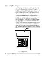
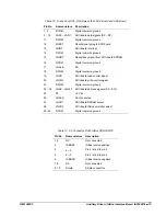
definition). Configuration of the interface is done with either the local keypad on the
LDCC board (see Figure 1) or the GE Control System Toolbox (toolbox). Refer to
the section,
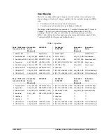
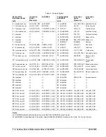
Data Mapping
.
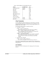
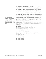
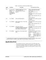
The ADII board has no fuses or hardware jumpers. Refer to the section,
Application
Data
for information on the LED indicators, testpoints, and connectors that are on
the board.
Note
The ADII board can only be used in AcDc2000 drives that have the LDCC
board. It cannot be used with previous design drive control and LAN communication
boards.
Figure 1. Keypad with Display


