background image

Service Manual 

I4X/EN CO/D 

ISTAT I4X 

Page 15/22 

9.5


Programming I4X settings using QDSP and Web browser


9.5.1 

QDSP setting software 


The  QDSP  setting  software  is  used  to  program  all  iSTAT  communicating  Measurement 
Devices  and  it  can  also  be  used  to  programme  the  IP  address  for  the  Ethernet  interface  of 
an I4X. 


The software is available free-of-charge from the GE Grid Solutions website. 


The  separate  QDSP  manual  includes  the  details  of  how  to  install  the  QDSP  software  on  a 
PC  and  how  to  program  the  PC

’s  Ethernet  port  to  allow  QDSP  to  interface  to  an  external 

Ethernet device and how to set an IP address in the I4X. 


The IP address used for the PC in local mode and in the I4X will depend on the requirements 
of  the  application  and  may  be  different  from  those  used  in  the  examples  in  the  QDSP 
manual. 


9.5.2 

Internet Browser 


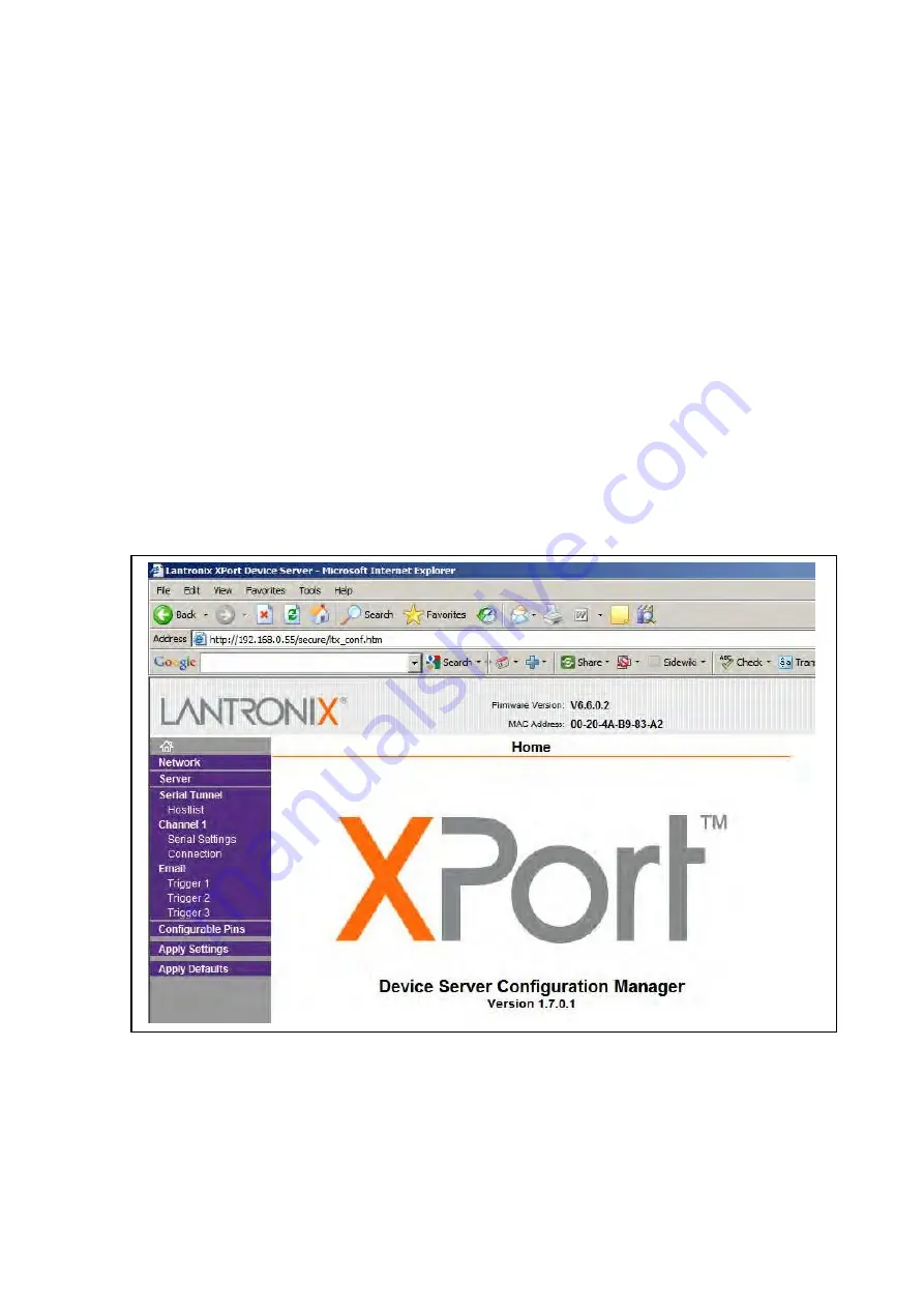
When  the  IP  address  has  been  confirmed  in  the  I4X  using  QDSP  it  is  now  possible  to 
address the setting pages in the I4X over Ethernet using a web browser. 


Open up the preferred web browser and enter the IP address of the I4X into the address line 
(i.e.  192.168.0.55)  and  press  <RETURN>.      The  web  interface  in  the  I4X  will  then  be 
displayed. 


Fitted   inside   the   I4X   is   a   Lantronix   device   which   implements   the   Ethernet   to   serial 
conversion. 


In the index on the left we are only interested in 2 options, 

‘Serial Settings’ and ‘Connection’ 

and in these windows only a few adjustments are required. 

Summary of Contents for iSTAT I4 Series

Page 1: ...GE Grid Solutions iSTAT I4X Communications Converter Manual Publication reference I4X EN CO D ...

Page 2: ......

Page 3: ...OSAL 8 6 TECHNICAL SPECIFICATIONS 9 6 1 Protective fuse rating 9 7 INTRODUCTION 11 7 1 General 11 7 2 iSTAT I4X Family 11 7 2 1 EIA RS 232 to EIA RS 485 2 wire 11 7 2 2 Ethernet to EIA RS 232 11 7 2 3 Ethernet to EIA RS 485 2 wire 11 8 CONNECTION MODES 12 8 1 EIA RS 232 to EIA RS 485 12 8 2 Ethernet to EIA RS 232 12 8 3 Ethernet to EIA RS 485 12 8 4 Status Indication Power 12 8 5 Status Indication...

Page 4: ...LE SHOOTING 18 10 1 EIA RS 232 to EIA RS 485 18 10 2 Ethernet to EIA RS 232 or EIA RS 485 18 11 TECHNICAL DATA 19 11 1 EIA RS 232 communications 19 11 2 EIA RS 485 communications 19 11 3 Ethernet communications 19 11 4 Universal Auxiliary Supply 19 11 5 Electrical Environment 20 11 6 Environmental withstand 21 ...

Page 5: ... its front plate frame or edges of the printed circuit board Avoid touching the electronic components printed circuit track or connectors 3 Do not pass the module to any person without first ensuring that you are both at the same electrostatic potential Shaking hands achieves equipotential 4 Place the module on an anti static surface or on a conducting surface which is at the same potential as you...

Page 6: ...Service Manual I400 EN M F iSTAT I400 Page 2 ...

Page 7: ......

Page 8: ...pment will be familiar with the contents of the Safety Section 1 2 Explanation of symbols and labels The meaning of symbols and labels may be used on the equipment or in the product documentation is given below Caution refer to product documentation Caution risk of electric shock Protective safety earth terminal Functional earth terminal Note This symbol may also be used for a protective safety ea...

Page 9: ...and current connections should be made using insulated crimp terminations to ensure that terminal block insulation requirements are maintained for safety To ensure that wires are correctly terminated the correct crimp terminal and tool for the wire size should be used Before energising the equipment it must be earthed using the protective earth terminal or the appropriate termination of the supply...

Page 10: ...eplaced with the recommended type and be installed with the correct polarity to avoid possible damage to the equipment 3 4 Insulation and dielectric strength testing Insulation testing may leave capacitors charged up to a hazardous voltage At the end of each part of the test the voltage should be gradually reduced to zero to discharge capacitors before the test leads are disconnected 3 5 Insertion...

Page 11: ...ny risk of electric shock Draw out case relays Removal of the cover on equipment incorporating electromechanical operating elements may expose hazardous live parts such as relay contacts Insertion and withdrawal of extender cards When using an extender card this should not be inserted or withdrawn from the equipment whilst it is energised This is to avoid possible shock or damage hazards Hazardous...

Page 12: ...y both poles of any dc supply the capacitors should be safely discharged via the external terminals prior to decommissioning Disposal It is recommended that incineration and disposal to water courses is avoided The product should be disposed of in a safe manner Any products containing batteries should have them removed before disposal taking precautions to avoid short circuits Particular regulatio...

Page 13: ...61010 1 2002 Class II EN 61010 1 2002 Class II Insulation Category Over voltage IEC 61010 1 2002 Category II 600V III 300V EN 61010 1 2002 Category II 600V III 300V Environment IEC 61010 1 2002 Pollution degree 2 600V 3 300V EN 61010 1 2002 Pollution degree 2 600V 3 300V Compliance is demonstrated by reference to generic safety standards Product Safety 73 23 EEC 2006 95 EC EN 61010 1 2002 Complian...

Page 14: ...Service Manual I4X EN CO D ISTAT I4X Page 10 BLANK PAGE ...

Page 15: ...ks with any protocol which can be transmitted over both RS232 and RS485 2 wire systems The use of digital technology achieves high reliability over a wide data speed range of 1200 to 115200 bits per second 7 2 2 Ethernet to EIA RS 232 The Ethernet to RS232 interface is uni directional the Master unit must be connected to the Ethernet port The unit works with the Modbus RTU protocol over RS232 and ...

Page 16: ...he table below I4X Auxiliary supply Ethernet port RS232 port Output device Terminals 13 14 10 100 RJ45 socket TX 26 RX 24 GND 25 TX RX GND The maximum cable length between the I4X and the RS232 device is 3 meters 8 3 Ethernet to EIA RS 485 There are three groups of terminals on the I4X the auxiliary voltage the Ethernet port and the RS485 port These are shown in the table below I4X Auxiliary suppl...

Page 17: ...ill be continuously lit or blinking for a 10Mb s connection or activity and the right hand LED for 100Mb s connection or activity 8 6 EIA RS 232 to computer socket connection When using RS232 to connect to a computer the RS232 connection can be made with either a 9 or 25 pin socket The connections are shown in the table below RS232 Port on I4X Computer DB9F terminal 9 pin Computer DB25F terminal 2...

Page 18: ...bus device address 9 3 Ethernet to EIA RS 485 The I4X Ethernet to RS485 communications interface requires that the settings for the Ethernet and the RS485 ports are configured prior to use in the application This can be done using QDSP and a Web browser All of the RS485 devices connected to the I4X must have the same serial settings as the RS485 port on the I4X Up to 31 x RS485 devices can be conn...

Page 19: ...ddress in the I4X The IP address used for the PC in local mode and in the I4X will depend on the requirements of the application and may be different from those used in the examples in the QDSP manual 9 5 2 Internet Browser When the IP address has been confirmed in the I4X using QDSP it is now possible to address the setting pages in the I4X over Ethernet using a web browser Open up the preferred ...

Page 20: ...ts these should be set to the same as the serial devices which are connected to the RS232 or RS485 port All other settings should not be changed from the defaults NOTE Even when an Ethernet to RS485 converter is being programmed the Protocol setting must remain as RS232 this is due to the internal construction of the I4X When settings are complete click OK ...

Page 21: ... being used in If the I4X communications interface is to be used in conjunction with a Com Port redirector program the local port should be selected within the range 14000 to 14010 When setting changes are complete click OK 9 5 2 3 Apply Settings To download the settings to the I4X click Apply Settings the download will be completed and the Lantronix interface will be rebooted automatically ...

Page 22: ...SP can be used to check If using a data speed of 115 200 b s try reducing this to a lower data speed e g 57 600 b s 10 2 Ethernet to EIA RS 232 or EIA RS 485 If communication with the communicating device cannot be established check for the following Is the I4X connected to a power supply check that the POWER LED is lit Is the I4X connected to the Ethernet Has the correct IP address been defined f...

Page 23: ...ation 3 7kVrms for 1 minute between all all other circuits Transmission mode Asynchronous Data rate 1200 to 115200 bps Connection type Single RJ45 socket Signal level 10 100 Base T Data rate 1200 to 115200 bps Protocol IEEE 802 3 Transmission rate 10M 100M bits per se Maximum cable length 100m Transmission mode Asynchronous 11 TECHNICAL DATA 11 1 EIA RS 232 communications s minute between all term...

Page 24: ... 1996 Class III 8kV air discharge 6kV contact discharge AC ripple on DC supply IEC 60255 11 1979 The unit will withstand 12 ripple on the DC auxiliary supply AC supply voltage dips and short interruptions EN 61000 4 11 1994 The unit will withstand voltage dips of 100 60 and 30 in the auxiliary power supply for a duration of 10ms under normal operating conditions without de energising The unit will...

Page 25: ...ic safety standards 600V Installation category II pollution degree II 300V Installation category III pollution degree III Protection Class II 11 6 Environmental withstand Atmospheric environment Temperature and humidity JVF DIN 40 040 Reference range of operation 0 C to 50 C Nominal range of operation 10 C to 60 C Storage and transit 40 C to 70 C Humidity to 95 non condensing Enclosure protection ...

Page 26: ...tained in this document is indicative only No representation or warranty is given or should be relied on that it is complete or correct or will apply to any particular project This will depend on the technical and commercial circumstances It is provided without liability and is subject to change without notice Reproduction use or disclosure to third parties without express written authority is str...

Reviews: