background image

(I) 

-- -- -

. .  

1; 

� 

� 

>-

L..J :j 

-

4: 

....1 

�  CL. 

CL. 

� 

-

t5 

II 

>-

....1 

� 

1-

ifi 

:z 

w  Q 

0:: 

� 

� 

0:: 

� 

CL. 

� 

1-

ffi 

0:: 

-

� 

CL 

II 

CL. 

""' 

GEK-49848A 

- � CL. 

�  =T 

w z o  

(I) - -

I :::E: CL. 

lN3Jij3d 

N I 

IOY�3AO 

-

� � iJS  

-

::.::

-

><  v 

w.J 

� - {1) 

CL.  I 

-· 

-

------ -

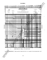
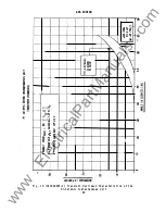
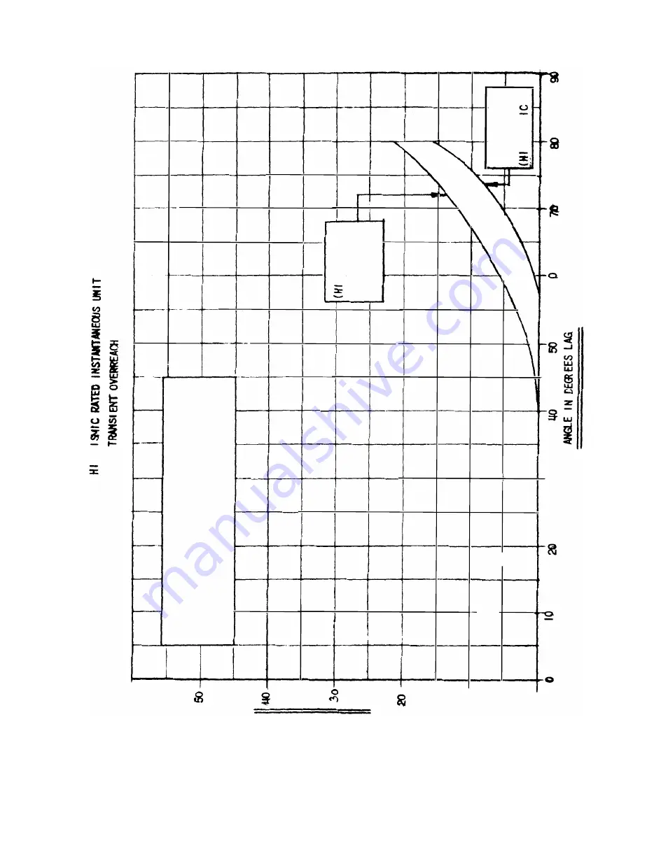
Fi g .   18  ( 0208A8694- 2 )   Tran s i en t   Overreach  C ha racter i s t i c s   of  the 

H i -S e i smi c  I ns tantaneo u s   U n i t 

49 

co 

� 

www 

. ElectricalPartManuals 

. com 

Summary of Contents for JBC51M

Page 1: ...ONS PHASE DIRECTIONAL OVERCURRENT RELAYS TYPES JBC51M JBC51M Y1A JBC51P JBC52M JBC52P JBC53M JBC53P JBC54M JBC77M JBC77P JBC78M GENERAL f ELECTRIC GEK 49848C w w w E l e c t r i c a l P a r t M a n u a l s c o m ...

Page 2: ...L IN UNITS 1 6 TIME OV ERCURRENT UNIT 1 7 DI RECTIONAL UNIT 1 9 INSTANTANEOUS OV ERCURRENT UNIT DI RE CTI ONALLY CONTROLLED 19 2 INSTANTANEOUS UNIT NON DIRE CTIONALLY CONTROLLED 1 9 INSTALLATION 20 L0CATI ON 20 MOUNTING 20 CONNECTI ONS 20 INSPECTIONS 20 OPERATION 20 TARGET AND SEAL IN UNITS 20 TIME OV ERCURRENT UNIT 21 DIRECTIONAL UNIT 21 INSTANTANEOUS OV ERCURRENT UNIT D I RECTIONALLY CONTROLLED ...

Page 3: ...e units respectively is connected in series with the contacts of the time overcurrent unit and the instantaneous overcurrent unit The contacts of each seal in unit respectively are connected in parallel with the contacts of the time overcurrent unit and the instantaneous overcurrent unit to provide protection for them and the associated control spring All the JBC relays are mounted in standard L2 ...

Page 4: ...t i s quadrature pol ari zed i e the 11a11 phase rel ay uses 11a11 phase current and b e vol tage etc The angl e of maxi mum torque of the di recti onal uni t i s a pproxi matel y 45 degrees i e maxi mum torque wi11 occur for rel ay current l aggi ng the uni ty power factor posi tion by 45 degrees or conversel y l eadi ng the quadrature vol tage by 45 degrees It i s someti mes the practi ce to use...

Page 5: ...tti ng I f sel ecti ve acti on of two or more rel ays i s requi red determi ne the maxi mum possibl e s hort ci rcui t current of the l i ne and then choose a time val ue for each rel ay that di ffers s uffi cientl y to ensure the proper sequence i n the o peration of the several ci rcu i t breakers Al l owance must be made for the ti me i nvol ved i n o peni ng each breaker after the rel ay conta...

Page 6: ...n seri es the o perati ng coi l rati ngs of al l three uni ts shoul d be consi dered i n determi ni ng the rati ng of the enti re o perati ng ci rcui t TI ME OVERCURRENT UNIT The one second rati ng of the TOC uni ts rel ay termi nal s 2 and 4 are al l 260 amperes The avai l abl e ta ps and the conti nuous rati ngs are s hown i n Tabl es 2 3 and 4 Note that separate tabl es are gi ven for the JB C5...

Page 7: ...H or L Sel ecti on of the hi gh or l ow range i s determi ned by the posi ti on of l eads T and E at termi nal 1 5 See Tabl e 6 and the appl i cabl e i nternal connections referenced i n Tabl e 1 For the H range connect 1 ead T to termi nal 15 and 1 ead E to the auxi l i ary termi nal that i s mounted on termi nal 1 5 For range L reverse l eads T and E TABLE 6 CONTINUOUS AND ONE SECOND RATINGS OF ...

Page 8: ... perate the target seal i n uni t DC RES ISTANCE 1 0 OHMS TABLE 7 SEAL IN UNIT RATINGS MIN OPERATING AMPERES 0 25 CARRY CONT AMPERES CARRY 30 AMPS FOR SEC CARRY 10 AMPS FOR SEC 60 HZ IMPEDANCE OHMS TELEPHONE RELAY AUXILIARY UNIT TAP 0 2 2 0 7 0 0 13 0 2 2 0 0 3 3 0 0 03 4 0 0 25 30 0 52 0 0 53 The DC operated auxi l i ary uni ts on model s JB C5 1 P JB C53 P and JB C77 P are rated 125 or 48 vol ts...

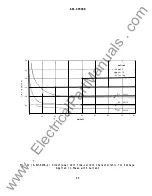
Page 9: ...nditions the rel ay wil l o perate repeatedl y within one or two per cent of the same time The time curves for the directional l y control l ed IOC units are s hown in Fig 1 6 The time current characteristic of the Hi Seismic non directional l y control l ed IOC unit is shown by Fig 1 7 and its transient overreach characteristic is shown by Fig 18 BURDENS The potential circuit burden of the direct...

Page 10: ...0 20 0 28 7 0 33 8 0 19 5 The impedance val ues gi ven are those for the mi nimum tap of each rel ay The impedance for other ta ps at pickup current tap rati ng vari es i nversel y a pproximatel y as the square of the current rati ng Exampl e for the very i n verse rel ays 1 5 12 amperes wi th impedance of the 1 5 ampere tap of 1 20 ohms the i mpedance of the three ampere tap at three amperes i s ...

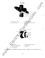
Page 11: ... l eft front whi ch control the time overcurrent uni t are s hown i n Fi g 1 9 They are of the 1ow gradi ent type s peci al l y constructed to mi nimi ze the effects of v i brati on Both the stati onary and movi ng contact brushes are made of 1 ow gradi ent materi al whi ch when subjected to vi brati on tend to fol l ow one another hence they resi st contact se parati on The contact di al A suppor...

Page 12: ...l ow i s i n such a di recti on as to cl ose a di recti onal un i t contact the uni t devel ops torque on the operating d i sk On model s equipped wi th a tel ephone rel ay a contact of the tel ephone rel ay control s the shad i ng coi l ci rcui t i n the same manner descri bed for the i nverse and very i nverse time uni ts The di sk sha ft carri es the mov i ng contact whi ch compl etes the trip ...

Page 13: ... l i nks provi ded on the rel ay these seri es or paral l el combi nati ons are connected i n seri es wi th the o perating coi l of the TOC uni t The i nner wi ndi ngs of the corner co i l s are al l connected i n seri es and i n turn are connected i n seri es wi th a ca paci tor and a contact of the di recti onal uni t Thi s ci rcui t thus control s the torque of the i nstantaneous overcurrent un...

Page 14: ...metal l i c chi ps Forei gn matter col l ected on the outs i de of the case may fi nd i ts way i ns i de when the cover i s removed and cause troubl e i n the operation of the rel ay ACCEPTANCE TESTS Immedi atel y upon recei pt of the rel ay an i nspection and acceptance test shoul d be made to ensure that no damage has been sustai ned i n shi pment and that the rel ay cal i brations have not been...

Page 15: ...front contact 3 The front contact shoul d cl ose approximatel y 0 005 to 0 010 i nch before the rear contacts Target and Seal i n Uni ts Instantaneous Uni t 1 The armature and contacts shoul d move freel y when operated by hand 2 Both contacts shoul d make at approximatel y the same time 3 The target shoul d l atch i nto v i ew just as the contacts make and shoul d unl atch when the target rel eas...

Page 16: ...rel ays i s affected by non si nusoi dal wave forms TARGET AND S EAL IN UNITS The target and seal i n un i t has an o perati ng coi l tapped at 0 2 and 2 0 amperes When used wi th tri p coi l s operati ng on currents ran gi ng from 0 2 to 2 0 amperes at the minimum control vol tage the target and sea1 i n tap screw s houl d be set i n the 0 2 ampere tap When the tri p co i l current ranges from tw...

Page 17: ... red to rotate the disk sl owl y and to cl ose the contacts shoul d be wi thi n fi ve percent of the val ue marked on the tap pl ate for any tap setting and time d i al pos i ti on I f thi s adjustment has been di sturbed i t can be restored by means of the s pring adjusti ng ri ng The ri ng can be turned by i nserti ng a screw dri ver bl ade i n the notches around the edge By turni ng the ri ng t...

Page 18: ...the rel ay shoul d be i nspected for tarni shed contacts 1 oose screws or other i mperfections I f any troubl e i s found i t shoul d be corrected i n the manner descri bed i n the secti on on SERV I CING CAUTI ON Every ci rcui t i n the drawout case has an auxi l i ary brus h I t i s espec i al l y i mportant o n current c i rcui ts and other ci rcui ts wi th s horti ng bars that the auxiliary br...

Page 19: ...i t to pi ck up at the des i red current l evel See the ACCEPTANCE TESTS secti on PERIOD I C CHECKS AND ROUTINE MAINTENANCE In view of the vi tal rol e of protecti ve rel ays i n the o peration of a power system i t i s i mportant that a period i c test program be fol l owed It is recogni zed that the i nterval between periodic checks wi l l vary depending upon envi ronment type of rel ay and the ...

Page 20: ... i ts support Th is screw shoul d be onl y l oose enough to al l ow the barrel to rotate i n i ts sl eeve but not so l oose as to al l ow the sl eeve to move w i th i n the support Wi nd the backstop screw in unti l the l ow gradi ent mov i ng and stati onary contact members just begi n to touch Wi nd the barrel contact in unti l the barrel contacts just begi n to touch Unwi nd the barrel contact ...

Page 21: ...ohm fi xed res istor shoul d be re pl aced wi th a n adjusta bl e resistor capabl e of provi d i ng the current range 1 i sted i n Tabl e 13 for the rel ay type and rating i n question A screw project i ng from the s ide of the mov i ng contact arm control s the c1 utch pressure and consequentl y the current value which wi l l cause the cl utch to sl i p Wi th rated frequency and at rated vol ts t...

Page 22: ...utch wi l l sl i p wi l l be i ncreased Pl ace the tap pl ugs i n the l ower range taps seri es Hol d the di recti onal uni t contacts cl osed Adjust the clutch so that the current at whi ch the cup just starts to sl i p fal l s wi thi n the l i mi ts l i sted i n Tabl e 14 TABLE 14 D IRECTIONALLY CONTROLLED IOC UNIT CLUTCH ADJUSTMENT PI CKUP RANGE SUDDENLY APPLI ED CURRENT SUDDENLY APPLIED CURREN...

Page 23: ...and deteri oration of the contacts Abrasive pa per or cl oth may l eave mi nute particl es of i nsul ati ng abras i ve materi al i n the contacts thus preventi ng contact cl os i ng The burni shi ng tool descri bed above can be obtai ned from the factory RENEWAL PARTS I t i s recommended that suffi ci ent quanti ti es of renewal parts be carri ed i n stock to enabl e the prompt repl acement o f an...

Page 24: ...ssion Li ne External Connecti ons for Three Si ngl e Phase Type JBC Rel ays wi th Auxi l i ary Tel ephone Type Rel ays for Di recti onal Phase Faul t Protecti on of a Si ngl e Transmi ssion Li ne Di recti onal Uni t Time current Characteristic for Vol tage Appl i ed i n Phase wi th Current Time current Characteri sti c of I nverse Time Overcurrent Uni t Time current Characteri sti c o f Very I nve...

Page 25: ...GEK 49848A Fi g 1 8043466 Type JBC51M Y1A Rel ay i n Case Front V i ew 29 w w w E l e c t r i c a l P a r t M a n u a l s c o m ...

Page 26: ...GEK 49848A Fi g 2 8043467 Type JBC51M Y1A Rel ay Removed from Case Front V i ew 30 w w w E l e c t r i c a l P a r t M a n u a l s c o m ...

Page 27: ...GEK 49848A Fi g 3 8043468 Type JBC51M YIA Rel ay Removed from Case Rear V i ew 31 w w w E l e c t r i c a l P a r t M a n u a l s c o m ...

Page 28: ...GEK 49848A Fi g 4 8043469 Type JBC77M Rel ay Removed from Case Rear V i ew 32 w w w E l e c t r i c a l P a r t M a n u a l s c o m ...

Page 29: ...C 2 C3 8 I OC I NSTANT OV ERCU RRENT U I NT C T O P T O C T I ME OV E R C U R RE N T U N I T C M I D SHORT F I N G ER 0 D I R E C TI ONAL U N I T C BO T 5 1 S E AL I N U NI T Fi g 5 0257A6174 Internal Connecti ons for JBC51M and JBC53M Rel ays Front View 33 w w w E l e c t r i c a l P a r t M a n u a l s c o m ...

Page 30: ...TOC I 3 5 2 4 I O C I N S TANT OV E RC U RRENT U N I T TOP T OC T I M E OVERCURRENT U NIT M I D D D I R E C T I ONAL U N I T C BOT S l S EA L I N U NIT 7 C 2 C 8 S HO RT F I N GER OC NO I N STA N T OVER C URRENT U N I T N ON D I RECT C M I O Fi g 6 0257A6189 l I nternal Connecti ons for JBC51M Y1A Rel ay Front V i ew 34 w w w E l e c t r i c a l P a r t M a n u a l s c o m ...

Page 31: ...j_ P I P O L ro c r 3 5 2 4 G I O C I N STANT OV ER CU RRENT U N I T TOP TO C T I ME OV ERCU RR ENT U N I T C M I D 0 D I R E C T I ONAL UNI T 80T 5 1 SEAL IN U NI T X AU X RELAY C 2 C3 V 67 8 SH O RT F I N G E R Fi g 7 0257A6190 I nternal Connecti ons for JBC5 1P and JBC53P Rel ays Front V i ew 35 w w w E l e c t r i c a l P a r t M a n u a l s c o m ...

Page 32: ... 4 IOC INSTANTANEOUS OVERCU R RENT U N IT lTOP TOC T IME OV E RCU RRE NT U N I T M I D O LE 0 D I R ECT I ONAL UN IT BOTTOM S I SEAL I N U N IT 7 2 roc c P 2 0 Rl P I P OT P O L c3 I SHORT F I NG E R Fi g 7a 0275A3820 I nternal Connecti ons for JBC52M and JBC54M 36 w w w E l e c t r i c a l P a r t M a n u a l s c o m ...

Page 33: ...D p p IOC C t Rl P I C3 D POT PO L I OC IHSTANT OV ERCU R R E NT U N IT TOP TOC T M E OVER CUR RENT U N IT M IDD LE SHORT F I N G EP D D I RECTI O NAL U N I T BO T TO M S I S EAL I N U N I T X AUXI LIARY RE L AY Fi g 7b 0275A4443 I nternal Connecti ons for JBC52P 37 w w w E l e c t r i c a l P a r t M a n u a l s c o m ...

Page 34: ... I POL TOC 1 5 2 4 l O t I N STAN T OVERCURRENT U NI T TOP T O C T I M E OV ERC U RRENT UNI T M ID 0 0 I R E C T I O NA L U NI T l B OT S l S EAL I N U NI T 7 C 2 C 3 S H O RT F rN G ER F i g 8 0257A6193 l I nternal Connecti ons for JBC77M Re l ay Front V i ew 38 w w w E l e c t r i c a l P a r t M a n u a l s c o m ...

Page 35: ... O L ro c b 1 r I 3 5 2 4 I OC INSTANT OVERCURRENT UNIT CTOP TOC TIME OVERCURRENT UNIT 0 4 JO 0 D I R ECTI ONAL UNIT BOT S S EAL I N U NIT X AU X R ELAY 7 C 2 C 3 s SH ORT F l N G E R Fi g 9 0257A6194 Internal Connecti ons for JBC77P Rel ay Front V i ew 39 w w w E l e c t r i c a l P a r t M a n u a l s c o m ...

Page 36: ...l IOC S l l O C 2 2 D C l OPE R 1 r b 3 5 7 2 4 6 8 IOC INSTANT OVERCURRENT UNIT lTOP TOC TlME OV ERCUR RENT U N IT M IDDLE D DtRECT lONAL UN IT BOTTOM S I SE AL IN U NI T 1 9 F i g 9 a 027 5A4439 1 I nternal Connecti ons for JBC78M 40 p P i I O C C t D POT P O L w w w E l e c t r i c a l P a r t M a n u a l s c o m ...

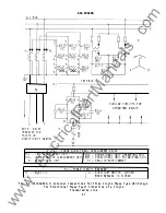
Page 37: ... I NG CO I L I OC I N STANTAN EOUS OV ERCU RRENT UN I T D PC D I RECT I ONAL UN I T POLAR I Z I NG CO I L D D I R ECT I ONAL UN I T S l SEAL I N W I TH TARGET 52 POWER C I RCU I T BREAK ER TC TR I P CO I L I a AUX I L I A RY SW I TCH C LOSED WHEN BREAK E R I S CLOSED Fi g 10 0418A0932 1 External Connecti ons for Three S i ngl e Phase Type JBC Rel ays for D i recti onal Phase Faul t Protecti on of ...

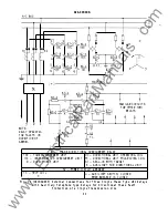
Page 38: ...ATI NG CO I L I OC I NSTANTANEOUS OVERCURRENT UN I T PC D I RECT I ONAL UN I T POLAR I Z I NG CO I L D D I RECT I ONAL UN I T S l SEAL I N W I TH TARGET X AUX I LI ARY FOR D I RECT I ONAL UN I T 52 POWER C I RCU I T BREAKER TC TR I P CO I L a AUX I L I ARY SWI TCH CLOSED WHEN BREAKER I S CLOSED Fi g 1 1 0418A0963 External Connecti ons for Three Si ngl e Phase Type JBC Rel ays wi th Auxi l i ary Te...

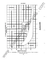
Page 39: ...0 V O L T S 6 0 C Y C L E S 1 0 VO LTS 2 5 V O L TS uo V O L T S 10 20 30 40 50 60 70 8 0 AM P ER E S Fi g 12 K 6154284 2 D i recti onal Uni t Time current Characteri sti c for Vol tage Appl i ed i n Phase wi th Current 43 w w w E l e c t r i c a l P a r t M a n u a l s c o m ...

Page 40: ...0 1 4 0 1 5 2 Q 2 5 3 0_ 4 0 5 Q 6 Q 0 8 0 1 0 1 2 2 Q 2 5_ 3 0 4 Q 5 Q 6 Q 7 0 8 Q I Q Q 1 2 1 6 r r r r 1 t t 10 t 9 r t 8 7 6 _ Cl c 1 4 3 G F _ 2 c I 0 r I G E 1 J 1 1 10 20 3D 50 10 10 1010 I i I II MULT I PLES OF R E L AY TAP S ET T ING I I I I Ull A DJU STMEti T S I H ST U N I CON T I N UOU S LY ADJUSTABLE 1 I DO J DO 3DO 2 1 J 3 2 1 5 ll 1 1 z 3 2 51 1 1 Dl OJ 03 12 01 I I I I l l Ill Fi g...

Page 41: ...4 0 I 2 0 2 5 3 0 1 0 J O fi 0 7 0 8 0 1 0 1 2 1 2 5 3 1 0 5 0 6 0 7 0 8 o 1 0 0 1 2 1 6 i I 1 t _ t I 1 t 10 9 _ r 8 _ _ t 7 Ul f t 6 co 5 c 4 t en 3 t 0 2 0 r E I t __ 1 2 I I I I 1 1 1 1 11 T ADJ U S TI1 EN 1 S I N S T U N I T CON T I NUOU SLY A UJ U S T A B L E I 7 I 7 I 20 11 1 1 I I J I 1 1 4 I I 1 I I ll II 10 1 1 10 I I I I I I ll I I I r 1 111 M U LT I P L E S O F REL AY TAP S E T TING Fi...

Page 42: ... 0 1 2 1 5_ 2 0 2 5 3 0 4 0 1 5 2 0 2 5 3 0 4 0 5 0 6 0 7 0 8 0 1 0 1 2 z o z s 3 o 4 o s o 6 o o s o 1 o o 1 2 1 5 l 1 10 0 t 1 7 6 Ill 5 01 4 3 Ill 2 0 0 1 I t _ Ill 1 E 2 1 fl I ADJ USTijEHTS I H ST UN I T CON T I NUOUSLY DJU ST A B L E 1 100 00 00 IGO I00 300 200 I I DO 0 7 I 3 2 I I 7 I I 01 07 01 01 01 li II I I 7 I I I I 7 1 10 20 30 ID 10 70 1000 I I II I I I I I I III M ULTIPLE S O F R E ...

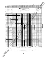
Page 43: ... I I i I I I j I I I I I I I I I I I j I I I i i i I I i i I I I_ 1 I i I i I j Li iJ_ __ ___ ___ _ _ _ ______ 1 1 1 1 l j I 1 1 1 1 1 i I i i I I t I I I i I I I I I I i I j i I I I i i j l t i t Fi g 16 0285A6663 Representative Time current Characteri sti c of D i rectional ly Control l ed I nstantaneous Overcurrent Un i t 47 w w w E l e c t r i c a l P a r t M a n u a l s c o m ...

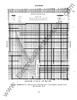
Page 44: ...c cr UJ li v I a c 0 10 I r 1 1 t I L I L _ v j 1 0 U 0 l n 8 0 SON003S N l 3WI dn ld Fi g 17 0208A8695 l Time current Characteri sti c of the H i Sei smic I nstantaneous Uni t 48 0 u c u 0 UJ J CL w w w E l e c t r i c a l P a r t M a n u a l s c o m ...

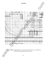
Page 45: ... CL 1 II CL m l GEK 49848A J 1 u CL T w z o I I E CL r 1 f lN3Jij3d N I IOY 3AO I iJS v w J 1 CL I Z rT t i 0 I Fi g 18 0208A8694 2 Trans i ent Overreach Characteri stics of the H i Sei smi c I nstantaneous Uni t 49 m a t O co 18 g 0 w w w E l e c t r i c a l P a r t M a n u a l s c o m ...

Page 46: ... Con i ca l Contact Ti p H Brush Retai ner F Bu tton Contact T i p G Mov i ng Contact Brush Retai ner A 8 _ c K Stati onary Con tact Support L Moun t i ng S crew M Locknuts Fi g 19 8023399 and 8027689 Low Gradi ent Contact Assembl y for the D i recti onal Uni t 50 w w w E l e c t r i c a l P a r t M a n u a l s c o m ...

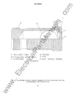
Page 47: ... B A L L C D I A PH RAM G C O N TA C T D SPA C ER E CA P c 0 E F FLA T S P I RA L S P R I N G Fi g 20 K 6077069 4 Barrel Contact Assembl y for the D i recti onal and the I nstantaneous Overcurrent Un i ts 51 G w w w E l e c t r i c a l P a r t M a n u a l s c o m ...

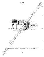
Page 48: ...848A ARMATURE OPfRATING ARM RESI DUAL SCREW LOC KNUT POLE PIECE Fi g 21 8012106 Typi cal Tel ephone Rel ay Type Auxi l i ary Uni t Used i n JBC Rel ays 52 w w w E l e c t r i c a l P a r t M a n u a l s c o m ...

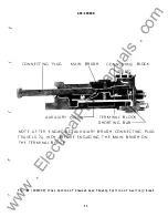
Page 49: ... A R NOT E A F T E R E N G AG I N G A U X I L I A R Y B R U S H CO N N E CT I N G P L U G T R AV E LS Y4 I N C H B E F0 R E E N G A G I N G T H E M A I N B R U S H 0 N T H E T E R M I N A L B LO C K Fi g 22 8025039 Cross Section o f D rawout Case S howi ng Pos i ti on o f Auxi l i ary Brush 53 w w w E l e c t r i c a l P a r t M a n u a l s c o m ...

Page 50: ...LL 2 0 HOLES 1 9MM FOR SEM I FLUSH MOUNT I NG FRONT V I E J 4 5 1 6 1 8 STUDS FOR SURFACE MTG ttl 1 9 1 7 1 5 1 3 1 1 0 0 0 0 0 0 0 0 0 0 1 9 875 2 0 1 8 1 6 1 4 1 2 5 04 MM STUD NUMBER I NG 9 7 5 3 1 0 0 0 0 0 0 0 0 0 0 1 0 8 6 4 2 BACK V I E J P A NEL D R I LL I NG FOR SURFAC MOUNT I NG FRONT V I EW TYP I CAL D I M 5 1 6 1 8 STUD 3 0 _ I 76MM I NCHES MM V I E J SHOW I NG AS SEMBLY OF HARDWARE FO...

Page 51: ...w w w E l e c t r i c a l P a r t M a n u a l s c o m ...

Page 52: ... 300 Meter and Control Business Department General Electric Company Protect1on and Control 205 Great Valley Parkway Malve rn Pennsylva n ia 1 9355 1 337 w w w E l e c t r i c a l P a r t M a n u a l s c o m ...

Reviews: