background image

Summary of Contents for JBCV51M

Page 1: ...I H3 0 I C n q 5 z C rn m I 0 I 1 m C I o z I C U ...

Page 2: ...NTS PAGE 3 INSTANTANEOUS UNIT NON DIRECTIONALLY 4 CONTROLLED 5 INSTALLATION 5 LOCATION MOUNTING 5 CONNECTIONS 6 INSPECTION CAUTION 6 OPERATION 6 TARGET AND SEAL IN UNITS 7 TIME OVERCURRENT UNIT 7 DIRECTIONAL UNIT 7 INSTANTANEOUS OVERCURRENT UNIT 7 DIRECTIONALLY CONTROLLED 7 INSTANTANEOUS UNIT NON DIRECTIONALLY 7 CONTROLLED 9 PERIODIC CHECKS AND ROUTINE 9 MAINTENANCE 9 TARGET AND SEAL IN UNITS 9 TI...

Page 3: ...ted control spring Those relays having the designation ViA following the model number also contain a Hi Seismic instan taneous unit of hinged armature construction This unit is non directional and has a self contained hand reset target that will show whenever the unit has operated All the JBCV relays are mounted in standard ill size drawout cases the outline and panel drilling dimensions for which...

Page 4: ...ses the extremely inverse time relay should be chosen as the time current curves more nearly match the fuse curve Another advantage of the extremely inverse relay is that it is better suited than both the inverse and very inverse relays for picking up cold load For any given cold load pickup capability the resulting settings will provide faster protection at high fault currents with the extremely ...

Page 5: ... entire operating circuit TIME OVERCURRENT UNIT The one second ratings of the TOC units relay terminals 2 and 4 are all 260 amperes taps and the continuous ratings are shown in Tables 2 3 and 4 Note that separate tables the JBCV51 JBCV53 and JBCV77 models TABLE 2 The available are given for CONTINUOUS RATING OF INVERSE TIME OVERCURRENT UNIT CONTINUOUS RATING OF EXTREMELY INVERSE TIME OVERCURRENT U...

Page 6: ...ating and impedance of the seal in unit for the 0 2 and 2 ampere taps are given in Table 7 The tap setting used will depend on the current drawn by the trip coil The 0 2 ampere tap is for use with trip coils which operate on currents ranging from 0 2 up to 2 0 amperes at the minimum control voltage If this tap is used with trip coils requiring more than two am peres there is a possibility that the...

Page 7: ...ble 5 RESET TIME OVERCURRENT UNIT Inverse time overcurrent units reset at 90 percent of the minimum pickup current very inverse time units at 80 percent and extremely inverse time units at 85 percent When the relay is de energized the time required for the disk to completely reset to the number 10 time dial position is approximately six seconds for inverse time relays and 60 seconds for very inver...

Page 8: ... 72 0 79 1 8 0 42 0 79 0 70 20 Extremely Parallel 4 16 0 13 0 25 0 28 0 5 0 46 0 28 0 28 7 Inverse 1 5 12 10 80 Series 10 40 0 16 0 29 0 33 0 7 0 49 0 33 0 33 8 Parallel 20 80 0 10 0 16 0 19 0 4 0 53 0 19 0 19 5 The impedance values given are those for the nhiriinium tap of each relay The impedance for other taps at pickup current tap rating varies inversely approximately as the square of the curr...

Page 9: ...ion cylinder construction provides higher torque and lower rotor inertia than the induction disk construction resulting in a faster and more sensitive relay Low Gradient Contact The directional unit contacts left front which control the time overcurrent unit are shown in Fig 17 They are of the low gradient type specially constructed to minimize the effects of vibration Both the stationary and movi...

Page 10: ...relays are mounted on the lOG middle unit On the JBCV53M Y1A relay the right hand seal in unit is replaced by the non directionally controlled lOG unit and the seal in unit is moved to the left side of the directional lower unit The left seal in unit operates in conjunction with the time overcurrent unit contacts and is labeled TIME Its coil is in series and its contacts in parallel with the main ...

Page 11: ...de when the cover is removed and cause trouble in the operation of the relay ACCEPTANCE TESTS Immediately upon receipt of the relay an inspection and acceptance test should be made to ensure that no damage has been sustained in shipment and that the relay calibrations have not been disturbed If the examination or test indicates that readjustment is necessary refer to the section on SERVICING These...

Page 12: ...current devices relays will be affected by the applied waveform Therefore in order to properly test alternating current relays it is essential to use a sine wave of current and or voltage The purity of the sine wave i e its freedom from harmonics cannot be expressed as a finite number for any particular relay however any relay using tuned circuits R L or RC networks or saturating electromagnets su...

Page 13: ...ap settings Pickup adjustment by means of the control spring applies to the JBCV51 and JBCV53 relays A different procedure applies to the JBCV77 relay For the JBCV77 relay the pickup of the unit for any current tap setting is adjusted by means of the variable resistor in the phase shifting circuit This adjustment also permits any desired setting intermediately between the various tap settings to b...

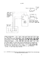
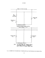
Page 14: ...the operating and polarizing circuits Note that during this test the restraint circuit is automatically disconnected by means of the test plug The polarity of the restraint circuit is automatically checked when it is reconnected or when the test plug is removed and the connection plug is reinserted With normal load and rated voltage the restraint circuit should always cause the directional unit co...

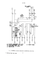
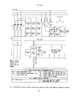
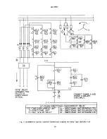
Page 15: ...he various relays are shown in Figs 5 to 7 Typical wiring diagrams are shown by Figs 8 and 9 Since phase sequence is important for the correct operation of Type JBCV relays the rotation specified in Figs 8 and 9 must be adhered to Unless mounted on a steel panel which adequately grounds the relay case it is recomended that the case be grounded through a mounting stud or screw with a conductor not ...

Page 16: ... be followed It is recognized that the interval between periodic checks will vary depending upon environment type of relay and the user s experience with periodic testing Until the user has accumulated enough experience to select the test interval best suited to his individual requirements it is suggested that the points listed below be checked at an interval of from one to two years These tests a...

Page 17: ...TS section that apply to the time overcurrent unit Also check reset voltage and time as outlined under RESET in the CHARACTERISTICS section low reset voltages or long reset times may indicate excessive friction caused by a worn bearing or by mechanical interference On JBCV77 relays set the relay on the two amp tap with the time dial set so that the contacts are just open Adjust pickup within the l...

Page 18: ...rew which secures the barrel contact to its support This screw should be only loose enough to allow the barrel to rotate in its sleeve but not so loose as to allow the sleeve to move within the support Wind the barrel backstop in until the low gradient moving and stationary contact members just begin to touch Wind the barrel contact in until the barrel contacts just begin to touch Unwind the barre...

Page 19: ...contact support The screw should be only loose enough to allow tne contact barrel to rotate in its sleeve The backstop screw fastened with a locknut should hold the moving contact arm in a neutral position i e with the arm pointing directly forward Then by rotating the barrel advance the stationary contact until it just touches the moving contact Next back it away 2 3 turn to obtain approximately ...

Page 20: ...insures the cleaning of the actual points of contact Fine silver contacts should not be cleaned with knives files or abrasive paper or cloth Knives or files may leave scratches which increase arcing and deterioration of the contacts Abrasive paper or cloth may leave minute particles of insulating abrasive material in the contacts thus preventing contact closing The burnishing tool described above ...

Page 21: ...GEK 49850 Fig 1 8043470 Type JBCV53M Y1A Relay in Case Front View 21 ...

Page 22: ...BLOCK INSTANTANEOUS OVERCURRENT CUP TYPE UNIT NON DIRECTIONAL INSTANTANEOUS UNIT ___ TIME OVERCURRENT UNIT BACK STOP INSTANTANEOUS DIRECTIONAL CUP TYPE UNIT Fig 2 C 8043471 Type JBCVS3M Y1A Relay Out of Case Front View TIME OVERCURRENT UNIT TAP BLOCK SEAL IN UNIT 22 ...

Page 23: ...GEK 49850 Cl U MAGNET COIL Hg 3 8043472 Type J8CV53M Y1A Relay Out of Case Rear View C2 __ 03 23 ...

Page 24: ...GEK 49850 WAMETRIC UNIT Fig 4 8043473 Type JBCV77M Relay Out of Case Rear View C2 04 Cl C3 24 ...

Page 25: ...C TIME OVERCURRENT UNIT M D 0 DIRECTIONAL UNIT BOT SI SEAL IN UMT Fig 5 0 51I 6198 0 Internal Connections for JBCV51M and JBCV53M Relays Front View RED JU1 A k LEADS 12 j 20 j L IOC LI D RESTR R USED WHEN f C2 P1 pQP 4 RI 1 I 8 10 SHORT F INGEk 4 25 ...

Page 26: ...ront View 0 5A r L RED JUMPER LEADS 19 r7 16 20 UZTOC P2 bc ND pj jCi RESTP P4 I D WOUND SHADING COILS U I0 OC INSTANT OVERCUkF ENT UNIT TOP SI fORT FINGER TOC TIME 0 ERCURRENT UNiT CMID D DIRECTI0NAL UT BOT SI SEAL IN UNIT IC r ND INSTANT OVERCLRkENT NIT NON DIRECT MID 26 ...

Page 27: ...C TtMf OVECU ENT UNIT MID D D R CTIONA4 UNIT SOT SI SEAL IN UNIT jq 7 0257A9686 Ii Internal Connections for JBCV77M Relay Front View Eo JUMPER LEADS 9 TOC SHADING hoc W0UN TOC P2 p COILS 0 C4 TCI 0 PESTR T 6 e I ORT FIN6ER Revised since last issue 27 ...

Page 28: ...S FOR FAULTS IN DIRECTION OF ARROW 61 PHASE DIRECTIONAL OVERCURRENT RELAY bC TIME OVERCURRENT UNIT OC DIRECTIONAL UNIT OPERATING COIL IOC INSTANTANEOUS OVERCURRENT UNIT PC DIRECTIONAL UNIT POLARIZING COIL D DIRECFIONAL UNIT RC DIRECTIONAL UNIT RESTRAINT COIL SI SEAL IN WITH TARGET 52 POWER CIRCUIT BREAKER IC TRIP COIL a AUXILIARY SWITCH CLOSED WHEN BREAKER IS CLOSED 28 ...

Page 29: ...3M Y1A 3 H 1 3 7 I D 67 I SI 6 7 67 I bc ND 321 67 TOC 67 I SI L 2 a CONNECT PHASE 2 AND PHASE 3 RELAYS TC SIMILARLY r 67 PHASE DIRECTIONAL OVERCUR RENT RELAY TOC TIME OVERCURRENT UNIT OC DIRECTIONAL UNIT cPERATINC COIL D DIRECTIONAL UNIT PR DIRECTIONAL UNIT POLARIZING COIL S I SEAL IN VIT f TAR f T RC DIRECTIONAL UNIT RESTRAINT COIL 29 ...

Page 30: ...0 z 4 C 4 C C 4 GEK 49850 PERCENT or PICK UP flPS Ar RATED VOLTS Fig 10 K 6507958 1 Directional Unit Pickup Characteristic with Balanced Voltages and at Maximum Torque Angle I I 0D 0 I 0 C 0 C 0 0 30 ...

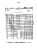
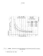
Page 31: ...GEK 4 9850 Fig 11 088880259 3 Time current Characteristic of Inverse Time Overcurrent Unit 0 I z 1 I I C MULTtPLES OF RELAY TAP SETTING 31 ...

Page 32: ... 91 0h 0 1rHr 19111 IN HI VI I I Ilidi I ONIJ L3S dV AV H O S3d iflb II I I IQIIIILIINII N IL I 1V N HI a II LI N N I 3 S N EEE EEE EE zz z HWHH1 U I Ni 9 I 0R0090S 0l 0 9 o i o I0 O D90 0h0l 5V0 I O90VrlV0V9I 1 10 1 1R01O90S0 j IHfl jOlt I I I I I I l_ I jul11 I I I IRHII I 11 0 dwL ODU HId 1J3 4XJ I I 11111 TIN NNILNN N U N NI NI NI NI III NI NI 111101 I 0 S lLI O96 i3 ...

Page 33: ... c_ j C1 C 0 N 5 CD CD CD I CD 4 CD C CD 5 C 5 5 ID rt r z ihw fEH Ej J DT TATA A7 r 5 z z i z c Time Dial Seitngs EE E E E C r 4 r El Cd 0 I o ii 4 1 4 441 z C CD CD CD EEE F i CD m CD CD 441 l a l a 704 I41 l a II 4400 law 0411 7100 1000 1000 Dow 0NOD3 NI WIJ ...

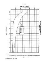
Page 34: ...UP PICUP SET1J A LOIER MN LOWER 2XMiN C HIGHER 4XUIN D HIGHER 8 X MIN Fig 14 0285A6663 Representative Time current Characteristic of Directionally Controlled Instantaneous Overcurrent Unit 34 GEK 49850 0 3D 3D 3D ci J Ip 92 Revised since last issue ...

Page 35: ...a 4 4 0 C U a 4 C 5 C i 4 C a 5 5 a 2 I 0 0 Cc r1 10 C I1 SEI94JC RATED lNSTkITNJUS t IIT OPERATING TIME N 025 0 6 010 005 N A OPERATIN6 TIME RANGE FOR ANY PICI UP SETTING 1 5 2 3 4 5 6 7 8 9 I 0 Si a C C U a MULTIPLSOF PIcKUp ...

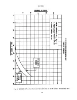
Page 36: ...p 4 GEK 49850 OVERREI I N PERCENT C I Fig 16 208A8694 2 Transient Overreach Characteristics of the Hi Seismic Instantaneous Unit 36 ...

Page 37: ...t Tip C Moving Contact Brush Retainer L K IA A Contact Dial B Stationary Contact Brush C Conical Contact Tip H Brush Retainer K Stationary Contact Support L Mounting Screw M Locknuts Fig 17 8023399 and 8027689 Low Gradient Contact Assembly for the Directional Unit 0 A 37 ...

Page 38: ...0 C CONTACT CD E D5PACER H CAP F FLAT SPIRAL SPRING Fig 18 K 6077069 4 Barrel Contact Assembly for the Directional and the Instantaneous Overcurrent Units A A B C INCLINED TUBE STAINLESS STEEL BALL D PH RAM 38 ...

Page 39: ...ER ENGAGING AUXILIARY BRUSH CONNECTING PLUG TRAVELS 1 4 INCH BEFORE ENGAGING THE MAIN BRUSH ON THE TERMINAL BLOCK Fig 19 8025039 Cross Section of Drawout Case Showing Position of Auxiliary Brush MAIN BRUSH AUXILIARY BRUSH TERMINAL BLOCK SHORTING BAR 39 ...

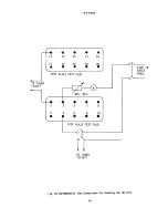
Page 40: ...IMER STOP 4 1 3 5 7 9 2 4 6 8 10 TYPE XLA13 TEST PLUG p ITO TIMER START Fig 20 0178A9036 0 Test Connections for Checking the TOC Unit 1 11 13 15 17 19 12 14 16 18 20 e I 120V I RATED FREQ TYPE XLA13 TEST PLUG 1 4 40 ...

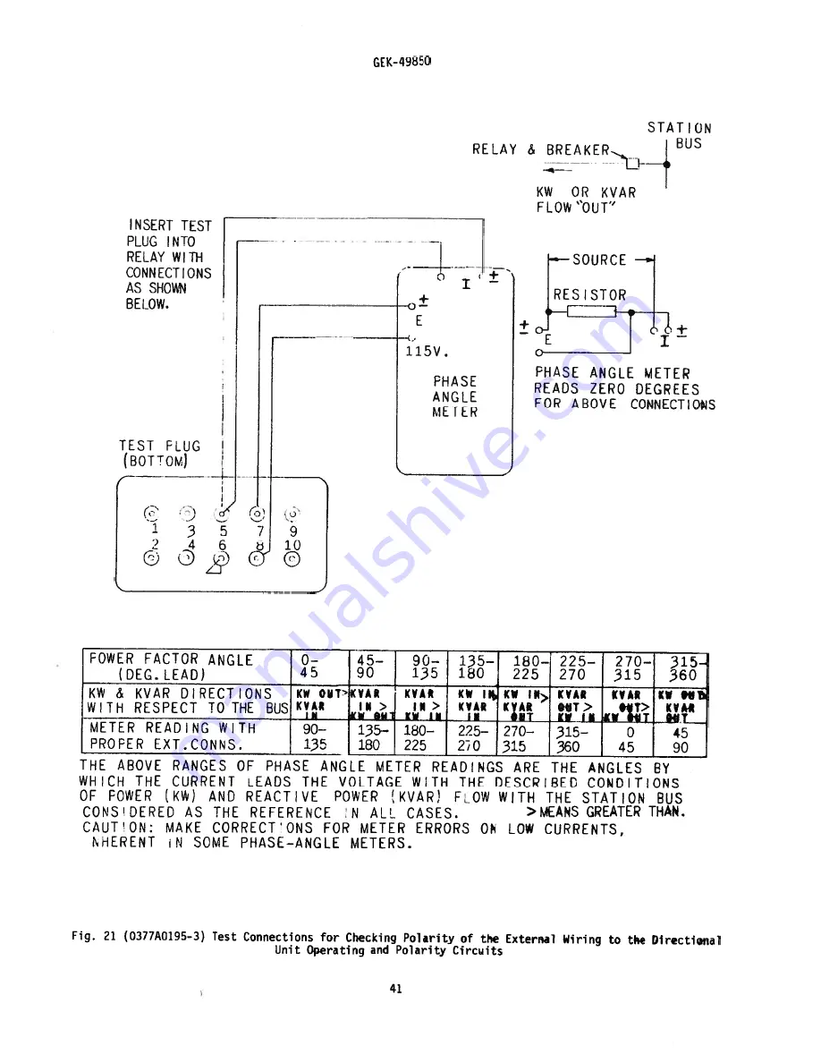
Page 41: ... 90 THE ABOVE RANGES OF PHASE ANGLE METER READINGS ARE THE ANGLES BY WHICH THE CURRENT LEADS THE VOLTAGE WTH THE DESCRIBED CONDITIONS OF POWER KW AND REACTIVE POWER VAR FLOW WITH THE STATION BUS CONSIDERED AS THE REFERENCE N ALL CASES MEANS GREATER THAN CAUTION MAKE CORRECTONS FOR METER ERRORS ON LOW CURRENTS HERENT N SOME PHASE ANGLE METERS Fig 21 0377A0195 3 Test Connections for Checking Polarit...

Page 42: ...STRAINING POLARITY NOTE THE DIRECTIONAL UNIT CONTACTS SHOULD CLOSE WHEN THE RELAY IS ENERGIZED WITH EITHER OF THE ABOVE CONNECTIONS Fig 2 0418A0971 o Test Connections for Checking Polarity of the Directional Unit Internal Wiring SOURCE OF RATED VOLTAGE OPERAT1 NG CO I L A OPERATING POLARITY 1 2 3 8 7 9 10 42 ...

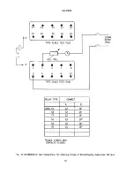
Page 43: ... TYPE CONNECT JBCG 51 12 19 53 12 19 54 13 19 78 13 4 BLOCK DIRECT UNIT CONTACTS CLOSED Fig 23 0178A9035 O Test Connections For Checking Pickup of Directionally Controlled IOC Unit TYPE XLA13 TEST PLUG 12OV RATED F REQ 43 ...

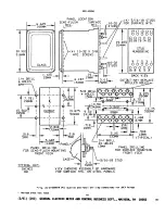
Page 44: ...tline and Panel Drilling Dimensions for JBCV Relays Revised since last issue i4 4 10 32 X 3 8 MTG SCREWS H 19 17 1513 11 00000 00000 2018 1614 12 STUD NUMBERING GLASS C 1 125 29MM 97531 00000 00000 10 8 6 4 2 BACK VIEW CUTOUT MAY REPLACE DRILLED HOLE PANEL DRILLING SEMI FLUSH MOUNTING FRONT VIEW PANEL DRILLING FOR SURFACE MOUNTING FRONT VIEW 2 91 200 GENERAL ELECTRIC METER AND CONTROL BUSINESS DEP...

Reviews: