


1
Questions? Call 866.GE.GRILL (866.434.7455)
or
Visit our Website at:
www.GEAppliances.com
READ CAREFULLY.
KEEP THESE INSTRUCTIONS
.
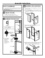
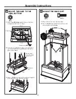
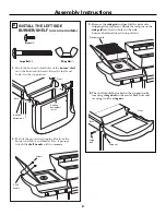
Assembly
Outdoor Cooking
Instructions
Center
Read these instructions completely and carefully.
•
IMPORTANT –
Observe all
governing codes and ordinances.
•
Note to Assembler –
Be sure to leave these
instructions with the Consumer.
•
Note to Consumer –
Keep these
instructions for future reference.
•
Skill level
– Assembly of this grill requires basic
mechanical skills.
BEFORE YOU BEGIN
•
Proper assembly is the responsibility of the assembler.
•
Product failure due to improper assembly is not
covered under the Warranty.
•
If you received a damaged grill, you should contact
your dealer.
•
Note –
Grill must be completely assembled before
any gas connections are made.
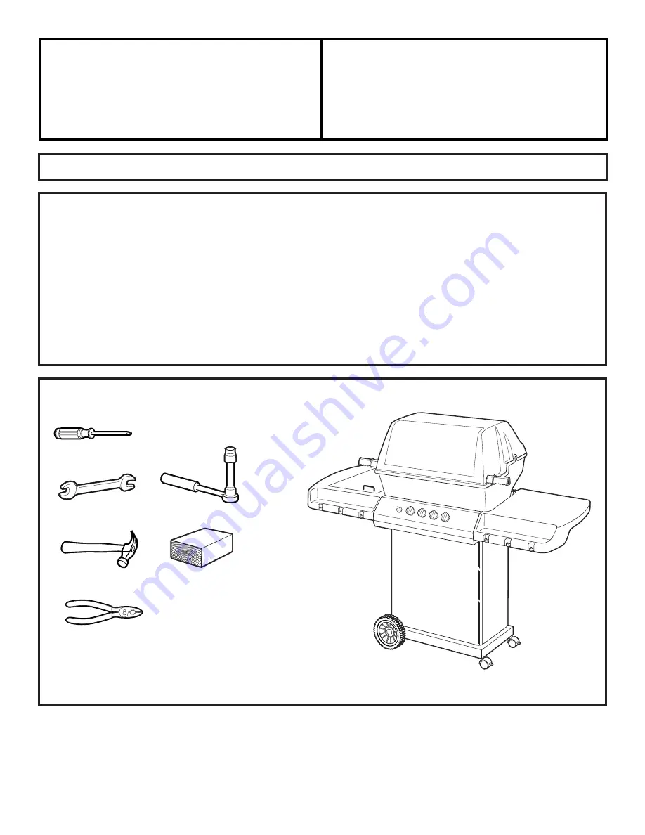
TOOLS YOU WILL NEED
Phillips screwdriver
7/16
″
open end wrench or deep socket with extension
Hammer
JGGB27, JGGN27, JGGR27
Pliers
Block of wood
Summary of Contents for JGGB27
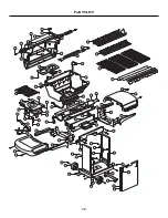
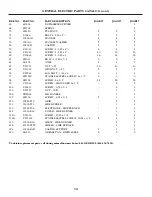
Page 12: ...12 PARTS LIST ...
Page 15: ...15 NOTES ...
Page 16: ...Part No 164D4290P035 Pub No 49 80077 1 05 01 JR Printed in Canada ...