background image

0150-0257A 

17 

Kalatel DVMRe-4L 

2.6  Display Options 

Available Multiscreen Displays 

Press the 

Multiscreen

 buttons to activate the multiscreen display.  Pressing the individual multiscreen 

button will display the corresponding multiscreen. 


B

A

B

A

Monitor A

Monitor B

4-Way

PIP


The multiscreen display is limited to the number of camera inputs on the unit. 


Four-Channel unit:

  Capable of displaying 4-way multiscreen and PIP. 

The camera assignments for each multiscreen is retained (in non-volatile memory) for both Live and 
Playback multiscreen mode on Monitor A. 

PIP: 

Use the Jog/Shuttle to adjust the location and size of the PIP display. Please note that the PIP 

display is only available on Monitor A in Live mode.


2.7  Active Cameos 

A cameo is defined as any cell within a multiscreen display.  Active Cameo mode allows the user to 
access and edit each cameo individually. 

Entering Active Cameo Mode 


While viewing a multiscreen, enter Active Cameo mode by pressing the 

Enter


button.  Active Cameo mode is indicated on-screen by flashing the number 
and titles of the active cameo and the LED above the Enter button is lit.  By 
default, the top left cameo is activated. 

Enter Button 

Selecting Cameos 


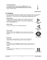
Select a cameo using the 

Jog/Shuttle 

to navigate the multiscreen. Rotating 

the Jog selects the next screen up or down a row.  Rotating the shuttle 
selects the next screen in numerical order. The active cameo will always be 
indicated by the flashing camera number and titles. 

Jog/Shuttle 

Selecting Cameras 

1


Display any camera in the active cameo by pressing the 

Number

 button of 

the desired camera.  Once a camera has been selected, the active cameo 
advances to the next cameo on the right. 

Number Button 

Summary of Contents for Kalatel DVMRe-4L

Page 1: ...K Ka al la at te el l D DV VM MR Re e 4 4L L Digital Video Multiplexer Recorder User Manual ...

Page 2: ...be illegal to dispose of this battery improperly under local state or federal laws Check with your local waste management officials for disposal and recycling options CAUTION Electrostatic Sensitive Device Use proper CMOS and MOSFET handing precautions including approved grounded wrists straps etc to avoid damage to this unit or its internal components from electric discharge WARNING This equipmen...

Page 3: ...ess written consent of GE Interlogix All information and specifications furnished by GE Interlogix are believed to be accurate and reliable No responsibility is assumed by GE Interlogix for neither its use nor any infringements of rights of third parties that may result from its use No license is granted by implication or otherwise under any patent or patent rights of GE Interlogix The Kalatel bra...

Page 4: ... 13 2 4 Playback 14 2 5 Recording 16 2 6 Display Options 17 2 7 Active Cameos 17 2 8 Sequencing 18 2 9 On screen Indicators 19 3 Menu System Overview 21 3 1 Menu Notation In This Manual 21 3 2 Accessing The Menu System 21 3 3 Available Menus 21 3 4 Menus In This Manual 22 3 5 Navigating The Menu System 22 3 6 Menu Shortcuts 22 3 7 The Main Menu 23 3 8 Time Date 23 3 9 Record 25 3 10 Alarms 28 3 11...

Page 5: ...ons During Playback 40 4 6 Alarm History Box 41 4 7 Searching For Recorded Alarms 41 5 Searching 42 5 1 Search Filters 42 5 2 Search Results 43 6 Technical Specifications 44 7 RS232 Remote Control Protocol 46 7 1 Front Panel Button Emulation 46 7 2 Configuration and Status 47 8 Warranty and Service 48 8 1 Factory Service 48 8 2 Warranty and Return Information 49 ...

Page 6: ... handling and motion detection functions they are considered secondary features This unit should not be the only alarm device on site Features Multiplexer functionality with built in digital recording 30pps pictures per second recording of up to 4 cameras Remote programming and control through the RS232 and Ethernet ports View live or recorded images remotely using WaveReader software Dual monitor...

Page 7: ...020 Power Cord 120 VAC P N 4310 0002 1 5 Installation Environment Power Ensure that the installation site s AC power is stable and within the rated voltage of the 12 Volt DC power supply If the site s AC power is likely to have spikes or power dips use power line conditioning or an Uninterruptable Power Supply UPS Ventilation Ensure that the location planned for the installation of the unit is wel...

Page 8: ...A Output Composite video output with BNC style connector 3 Y C Monitor A Output Y C video output with 4 pin mini DIN style connector 4 Alarm I O For connecting alarm inputs and alarm output relays 5 Power Input For connecting the power supply 6 Aux Port Not Used 7 RS485 Port 1 Connector Not Used 8 10 100 Ethernet Port For connecting to remote PC via ethernet network 9 Composite Monitor B Output Co...

Page 9: ... set the termination of the monitor as Hi Z High Impedance Y C Monitor Output Monitor A only Y C video output has a 4 pin mini DIN style connector This style of connection is also referred to as SVHS and S Video Cable 75 Ohm Coaxial Connectors BNC Alarm I O Port The back panel of the unit is equipped with an Alarm Port DB 25 style connector Do not attempt to wire directly to the DB 25 connector on...

Page 10: ...in 23 to either pin 18 19 or 20 ground pins All specifications subject to change without notice GE Interlogix believes all specifications to be correct at time of printing but no liability is assumed for omissions or errors Ethernet Port Wire Type Cat 5 Connector Type RJ 45 Max Cable Length 100 meters 328 ft Min Cable Length 6 feet 1 8 meters Hub Wiring Configuration Straight Through PC Wiring Con...

Page 11: ...e the monitors and all of the cameras 2 Energize the DVMRe 4L Voltage 12 Volt DC Power 60 Watt 5 Amp Connector 2 1mm barrel center positive Once power is applied to the unit it will begin its power up procedure The unit will begin by displaying the software version on Monitor A and then the unit will begin recording automatically Check Video Input Quality Check the picture quality by selecting eac...

Page 12: ...erse Play Button Playback in Reverse 6 Freeze Button Freezes camera images on screen in Live mode Pauses Playback 7 Play Forward Button Begins Playback 8 Jog Shuttle Controls Playback speed and Menu selections 9 Menu Button Provides access to on screen menus 10 Power Indicator Indicates power on off condition 11 Alarm button Allows user to acknowledge and silence alarms 12 Sequence Button Sequence...

Page 13: ...ce list is programmable For detailed information about programming the sequence list see section 2 8 Sequence Button Zooming To activate the 2x digital zoom select the full screen display of the camera you wish to zoom then press the Zoom button Zooming will be indicated by the LED located directly above the Zoom button Zooming is also indicated as ZOOM on the primary monitor Zooming works with fr...

Page 14: ...ed While in Playback mode the user may change the playback direction playback speed etc To return to Play Forward operations press the Play Forward button Play Forward Button Reverse Play To begin reverse playback press the Reverse Play button Reverse Play Button Fast Forward During playback rotate the Shuttle the outer dial clockwise to view data at a higher than normal rate Increasing the amount...

Page 15: ...y pressing the Number button of the desired camera Pressing the Camera number button again displays the Status Display Box Number Button Sequenced Full Screen Display While in a Full Screen display press the Sequence button to begin full screen sequencing The sequence list is programmable For detailed information about programming the sequence list see section 2 8 Sequence Button Zooming To activa...

Page 16: ...cording will be indicated by the LED located directly above the Record button The unit always starts recording at the end of previously recorded data The unit will continue recording until the record button is pressed again unless Record Lock is ON Record Button The DVMRe 4L also remembers its current record mode in the event of power loss If the unit was recording during a power loss then when po...

Page 17: ...fined as any cell within a multiscreen display Active Cameo mode allows the user to access and edit each cameo individually Entering Active Cameo Mode While viewing a multiscreen enter Active Cameo mode by pressing the Enter button Active Cameo mode is indicated on screen by flashing the number and titles of the active cameo and the LED above the Enter button is lit By default the top left cameo i...

Page 18: ... Monitor button select the monitor to be programmed Then using a Number button select any camera for full screen display The unit must be in Full Screen Display mode before starting to create the sequence list This initial camera is not part the sequence list To begin recording the Autolist sequence Press the Alarm button and Sequence button simultaneously Autolist Program mode is indicated as PGM...

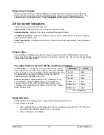
Page 19: ...tem see section 3 12 The user can change display position and color See below Changing Position And Color Of Title And Status Indicators Position Color Top Left Black Top Left White Top Left Gray Bottom Left Black Bottom Left White Bottom Left Gray Camera Titles To change the color and position of the camera titles select a camera for full screen display then press the Enter button to advance to t...

Page 20: ...isplay Box A Status Display Box can be viewed by pressing the Camera Number button twice Status Indicators include On Live Fullscreen Archive Status Not Connected This feature is not available on this model Network Displays all current Network connections Normal connection is displayed as ip ip or if there is no connection Live connections are displayed as E1 ip ip E2 ip ip etc where ip ip represe...

Page 21: ...me Date Time Date 3 2 Accessing The Menu System Enter the menu system by pressing the Menu button A Password Box will appear on the primary monitor Enter either the Operator Password Providing limited access to the menu system Only the Operator and System View menus are available Menu Button Installer Password Providing complete menu access Use the Number buttons to enter the appropriate password ...

Page 22: ...ems Hit the ENTER button to select the highlighted menu item Exiting Menus Press the Menu button to exit a menu From the menu bar press the Menu button to exit the menu system completely Shuttle Shuttle Jog Jog Main Time Date Record Alarms Motion Detection Camera Setup Communications Front Panel Lock Factory Settings Passwords Operator 3 6 Menu Shortcuts Zoom Button In menu lists that have 2 setti...

Page 23: ...vigate 4 Press the Enter button to confirm the selection and exit the edit mode 5 To save the changes and exit the menu Rotate the Jog to select OK then press the Enter button 6 To exit the menu without making changes Rotate the Jog to select CANCEL then press the Enter button q Main Menu Time Date Set Date 1 Press the Enter button the highlighting will move to the row of numbers 2 Enter the date ...

Page 24: ... Sunday in April DST ends at 02 00 on the last Sunday in October Includes United States except Hawaii American Samoa Guam Puerto Rico Virgin Islands parts of Indiana and Arizona and Canada except Saskatchewan EUR DST starts at 01 00 GMT on the last Sunday in March DST ends at 01 00 GMT on the last Sunday in October Includes European Union Countries AUS DST starts at 02 00 on the last Sunday in Oct...

Page 25: ... TL Records at the Time lapse Record Rate under normal conditions Records at the Event Record Rate during events This is the default setting About Events An Event is an action that the unit acknowledges by recording at the Event Record Rate yet it is not cause for an Alarm Events are created by Activity detection Example of an Event A camera is pointed at the front door inside the lobby during bus...

Page 26: ...y each lasting 3 minutes on average then the of the time will be 1 hour 24 hours 4 1 Rotate the Jog to navigate and the Shuttle to change the values 2 To save changes and exit the menu Select OK and then press the Enter button 3 To exit the menu without making changes Press the Menu button or select CANCEL then press the Enter button Record Quality Use this setting to specify the record quality fo...

Page 27: ... in Time lapse Activity Event and or Alarm record mode The maximum record rate per camera is inversely proportional to the number of cameras connected to the unit The fewer cameras connected the higher the maximum record rate for each camera and vice versa The maximum record rate for multiple cameras is 30pps q Main Menu Record Alarm Event Actions Pre Event Duration The unit will record up to 5 se...

Page 28: ...ta from the hard disk with the possibility of restoring it Undelete Restore data that has been deleted but not yet overwritten Destroy Erase all data from the hard disk permanently without the possibility of restoring it Selecting this option brings up a confirmation dialog box q Main Menu Record Record Lock The Record Lock feature prevents Recording from being halted from the Front Panel Turning ...

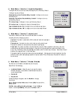
Page 29: ...tomatically silenced and acknowledged If the alarm input exceeds the duration specified in this menu the unit silences and acknowledges the alarm when the alarm input ceases Select the timeout duration the range is from 1 to 250 seconds Transparent alarms cannot be silenced and acknowledged If transparent mode is preferred but the ability to silence and acknowledge alarms is desired select Timed O...

Page 30: ...detection Activate the on screen motion detection indicator Set motion detection as Activity detection or Intrusion Detection Configure the motion detection parameters on a per camera basis q Main Menu Motion Detection Enable Disable Detection Selecting Enable All or Disable All from this menu will activate or deactivate motion detection on all cameras Selecting Individual Enable from this menu wi...

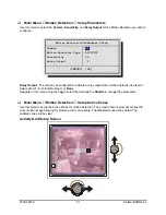
Page 31: ...it may be configured to activate a relay output when motion detection is present Select either 1 2 1 2 both relays or None Navigate in this menu using the Jog to select the field and the Shuttle to change the parameters q Main Menu Motion Detection Setup Active Zones Use this menu to setup the Active Zones for motion detection The screen shown below will overlay the current video image allowing fo...

Page 32: ...the screen The black bar raises and lowers to indicate the degree of motion detected When the black bar reaches the red bar a motion detection alarm is activated Adjusting Motion Detection Sensitivity Raise and lower the red bar to change the motion detection sensitivity Use the Play Forward button to increase the sensitivity level and the Play Reverse button to decrease the sensitivity level The ...

Page 33: ...XYZ Camera Title Camera 01 1 CANCEL OK Camera Title Edit Menu 1 With the camera title selected press the Enter button The menu will enter the Edit mode and the character bank will appear in the center of the menu 2 Press the Sequence button to select the desired character set 3 Rotate the Shuttle to navigate the cursor in the camera title 4 Rotate the Jog to navigate the cursor in the character ba...

Page 34: ...g to navigate and the Shuttle to change the values Save changes and exit the menu Select OK then press the Enter button Exit the menu without making changes Press the Menu button or select CANCEL then press the Enter button 3 13 Communications Use this menu to Configure the baud rates and settings for the RS232 ports Configure the Ethernet address and networks settings q Main Menu Communications R...

Page 35: ...otate the Shuttle to navigate the Modem Init String 4 Rotate the Jog to select a character from the character bank 5 Use the Number 2 button or rotate the Shuttle to insert the desired character from the character bank into the Modem Init String and advance to the next character 6 Use the Number 1 button to insert a blank character 7 When finished press the Enter button 8 To save the changes and r...

Page 36: ...e settings if DHCP is not enabled Primary Name Server Backup Name Server The IP addresses of the Primary and Backup Name Servers Not required if DHCP is enabled Print Server Enter the Print Servers IP address to enable the Print Image operation Function and Zoom TCP MTU Size Select from Standard 1400 and 1200 The MTU describes the maximum possible TCP packet size Standard 1500 is optimal for most ...

Page 37: ...king changes Press the Menu button 3 16 Passwords Use this feature to change the Installer Operator or Ethernet passwords Changing the Installer or Operator Passwords To change the password 1 Highlight the password you wish to change then press the Enter button A password box will appear 2 Enter the new password using the Number buttons 3 Highlight OK then press the Enter button 4 Re enter the pas...

Page 38: ...nitor display setup options so that the user may personalize the monitor displays during their shifts Other options include alarm history and changing the operator password None of the items are unique to the Operator menu All items located in the Operator menu are also found in the Main menu q Operator Menu About DVMR About DVMR menu This menu provides information such as Model Designation Serial...

Page 39: ...rom the Operator menu Operator Menu Item Primary Menu Location Section In Manual Time Date Display Main Menu Time Date Time Date Display 3 8 Titles Display Main Menu Camera Setup Camera Titles Title Display 3 12 Alarm History Main Menu Alarm Alarm History 3 10 Operator Password Main Menu Password Operator Password 3 16 ...

Page 40: ...tion of the alarm Record Rate Record Rate can be increased by recording at the Alarm Record Rate see section 3 10 and by Interleaved or Exclusive Recording see Alarm Record mode in section 3 10 4 3 Alarm Acknowledge Pressing the Alarm button acknowledges to the unit that the alarm has been recognized and silences the internal buzzer This does not clear the alarm condition Alarm Button 4 4 On scree...

Page 41: ...larm button is lit for the duration of the alarm Monitor A Multiscreen Each camera in alarm is indicated on screen by a flashing red A in its cameo Alarm LED lights to indicate an alarm condition There is no change in the playback or Triplex multiscreen based on playback of recorded alarms 4 6 Alarm History Box The Alarm History feature provides a list of the 100 most recent alarms View the Alarm ...

Page 42: ...ation Play from Disk DATE MM DD YY TIME HH MM Start Stop Start Stop 01 27 02 01 27 02 20 57 20 59 Activity Event Alarm Text Camera 1 2 3 4 X X X X CANCEL START SEARCH CAMERA key selects deselects individual cameras ZOOM key selects deselects except 1 all cameras Hit Camera buttons to select deselect individual cameras Use the Zoom button to globally select deselect cameras to search X X X X Select...

Page 43: ... 0 00 00 38 003 01 21 2002 20 10 10 0 01 07 22 004 01 22 2002 20 07 10 0 00 00 07 005 01 23 2002 20 07 10 0 00 08 56 006 01 24 2002 20 07 10 0 00 00 06 007 01 25 2002 20 07 10 0 05 57 31 008 01 26 2002 20 07 10 0 00 46 43 000 01 21 2002 20 07 10 0 04 35 15 PLAY REV FWD to page up down ENTER to play event SEQ to repeatedly play event 9 matches found Press the Menu button to exit the Search Results ...

Page 44: ...nnector RS232 Port 2 Not used on this model Camera Inputs BNC connectors Auto Terminating Color Mono Monitor A Output Y C 4 pin Mini DIN Connector Monitor B Output Y C 4 pin Mini DIN Connector Monitor A Output Composite BNC Connector Monitor B Output Composite BNC Connector RS485 Port Not used on this model Alarm I O Port DB 25 Female Connector Video Video Signal Input 0 5 to 2 0 Volts peak to pea...

Page 45: ...en Indicators Status Retrievable via RS232 port Motion Detection Zones Per Camera 256 16 x 16 grid Sensitivity Settings 10 levels Gray Levels Per Zone 256 levels Motion Detection Status Output Relay Outputs Link to Alarms Link to Events On screen Indicators Status retrievable via RS232 port Part Numbers Rack Mount Kit CBR RK6 1U Height Part Number 0110 R601 Replacement Manual 0150 0257A ...

Page 46: ...eserved 17 Reserved 18 Reserved 19 Reserved 20 Reserved 21 Reserved 22 Reserved 23 Reserved 24 Reserved 25 40 Menu 41 Enter 42 Reserved 43 Reserved 44 Reserved 45 49 Monitor B 50 Reserved 51 63 Left Arrow 64 Right Arrow 65 Up Arrow 66 Down Arrow 67 Reserved 68 74 Alarm and Sequence 75 Alarm and Camera 1 76 Alarm and Camera 2 77 Alarm and Camera 3 78 Alarm and Camera 4 79 Reserved 80 Reserved 81 Re...

Page 47: ... block 255 must be set to 0 iii Requesting data from the DVMRe When a message of type 0xBB is sent to the DVMRe 4L it will respond by sending 16 bytes of requested data a Read Alarm History List Byte 1 0xFF Byte 2 0xBB Byte 3 0 Byte 4 0x09 When the Read Alarm History List message is received by the DVMRe 4L it responds by sending a start byte 0xFF followed by ASCII strings for every alarm event in...

Page 48: ... Authorization number RMA The unit s serial number must be provided before a RMA number can be issued Units returned to the factory for service must have freight and insurance prepaid and must show the RMA number clearly on all shipping documents The failure symptoms must be clearly described by the operator and enclosed with the unit together with a copy of the original suppliers invoice Failure ...

Page 49: ...l non warranty repairs the customer will be billed for parts labor and shipping Labor will be billed in half hour increments Note Customers requesting an estimate prior to repair will be notified by phone If they cannot be reached they will be notified by fax If we are unable to reach the contact person for repair authorization after one phone attempt and two fax attempts the equipment will be ret...

Page 50: ...0150 0257A ...

Reviews: