background image


20 

Kilsen KFP-CF Series Operation Manual 


Summary of Contents for Kilsen KFP-CF Series

Page 1: ...GE Security P N 501 415103 2 10 REV 1 0 ISS 01MAY09 Kilsen KFP CF Series Operation Manual ...

Page 2: ...rers or vendors of the respective products Intended use Use this product only for the purpose it was designed for refer to the data sheet and user documentation for details For the latest product information contact your local supplier or visit us online at www gesecurity eu Certification and compliance European Union directives 2002 96 EC WEEE directive Products marked with this symbol cannot be ...

Page 3: ...interface for two and four zone control panels 3 User interface for eight zone control panels 4 Operator controls and indicators 5 Acoustic indicators 7 Summary of status indications 7 Control panel operation 10 Access levels 10 Basic operation 11 Advanced operation 13 Maintenance 17 Fire alarm system maintenance 17 Battery maintenance 18 Product compliance 19 ...

Page 4: ...II Kilsen KFP CF Series Operation Manual ...

Page 5: ...ur and eight zone models is not available for all operating modes See Sounder and fire routing delays on page 2 Operating modes Supported operating modes are shown in the table below The default operating mode is EN 54 2 Table 1 Operating modes Operating mode Region EN 54 2 default European Union EN 54 2 Evacuation European Union Spain EN 54 2 Scandinavia European Union Scandinavia BS 5839 1 Unite...

Page 6: ...s delay availability for each operating mode Table 2 Sounder and fire routing delays Operating mode Sounder delay Fire routing delay Extended fire routing delay EN 54 2 Yes Yes No EN 54 2 Evacuation Yes No No EN 54 2 Scandinavia Yes Yes Yes BS 5839 1 Yes No No NBN S21 100 Yes No No NEN 2535 No Yes Yes Note Fire routing is not available on any two zone control panel ...

Page 7: ... Sounder Fault Disable Test button and LED 6 Sounder Delay button and LED 7 Network Fault LED 8 Service Detector LED 9 Expansion I O Fault Disabled LED 10 General Disable button and LED 11 General Test button and LED 12 Configuration controls 13 Reset button and LED 14 Panel Silence button and LED 15 Sounder Start Stop button and LED 16 System Fault LED 17 Out of Service LED 18 Earth Fault LED 19 ...

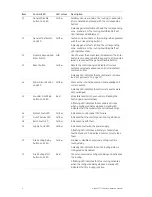
Page 8: ...ED 6 Sounder Delay button and LED 7 Network Fault LED 8 Service Detector LED 9 Expansion I O Fault Disabled LED 10 General Disable button and LED 11 General Test button and LED 12 Configuration controls 13 Reset button and LED 14 Panel Silence button and LED 15 Sounder Start Stop button and LED 16 System Fault LED 17 Out of Service LED 18 Earth Fault LED 19 Supply Fault LED 20 Fire Routing Delay b...

Page 9: ...y LED Green Indicates that the system is powered up correctly 3 General Fault LED Yellow Indicates a fault The corresponding zone device or function fault LED also flashes 4 General Fire Alarm LEDs Red Indicates a fire alarm Flashing LEDs indicate that the fire alarm was activated by a detector Steady LEDs indicate that the fire alarm was activated by a manual call point The corresponding zone ala...

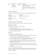
Page 10: ...nce button and LED Yellow Silences the internal buzzer and acknowledges all current events A steady LED indicates that all current events were acknowledged 15 Sounder Start Stop button and LED Red Stops silences all active sounders Pressing the button again restarts them A flashing LED indicates that sounders activate when a configured delay elapses A steady LED indicates that the sounders are act...

Page 11: ...ED is steady If a fire routing delay was enabled the Fire Routing Delay LED is steady There are no acoustic indications Fire alarm Fire alarm status is indicated as follows The general Fire Alarm LEDs are flashing if the alarm was activated by a detector or steady if the alarm was activated by a manual call point The corresponding zone alarm LEDs are flashing if the alarm was activated by a detect...

Page 12: ...ding zone Fault Disable Test LEDs are steady There is no acoustic indicator Disabled sounders are indicated as follows The general Disable LED and the Sounder Fault Disable Test LEDs are steady There is no acoustic indicator Disabled fire routing is indicated as follows The general Disable LED and the Fire Routing Fault Disable Test LEDs are steady There is no acoustic indicator Disabled expansion...

Page 13: ...state there is no further fire alarm or fault warning and all panel operation stops Out of service is indicated as follows The Supply LED flashes if there is no mains power and the battery voltage is insufficient The Supply LED is steady if the mains power is insufficient and no battery power is detected The Out of Service LED is steady The internal buzzer sounds intermittently When power is re es...

Page 14: ...r authorized users who have been trained to operate the control panel The default access level 2 password is 2222 The tasks you can perform at this access level are detailed in the topic Advanced operation on page 13 Entering access level 2 To enter access level 2 1 Enter the access level 2 password using the numeric keypad 2 Press Enter A long beep and a steady Reset LED indicate that the correct...

Page 15: ... to cancel the delay and activate sounders immediately A sounder delay is indicated as follows A steady Sounder Delay LED indicates that a delay is enabled A flashing Sounder Start Stop LED during a fire alarm indicates that the configured delay is active sounders are activated when the configured delay elapses or when the delay is cancelled A fire alarm activated by a manual call point overrides ...

Page 16: ...s and hold the Test button for three seconds or more The test is indicated as follows The general Fault and System Fault LEDs flash All other LEDs are steady The internal buzzer sounds constantly The test continues for as long as the Test button remains pressed with an automatic timeout of twelve seconds When the test is completed the control panel returns to its former state ...

Page 17: ...ing Sounder Start Stop LED indicates that a configured sounder delay is active to cancel an active sounder delay see Cancelling an active sounder delay on page 11 Note Sounder functionality is defined by your system configuration settings and stopped sounders may restart automatically if another alarm event is detected Contact your fire system installation or maintenance contractor to confirm your...

Page 18: ...m LEDs and Zone alarm LED are steady or flashing depending on the source of the alarm Fire routing and other zone dependent functions are not activated Unless configured otherwise the sounders are activated for five seconds and the Sounder Start Stop LED is steady see note Unless configured otherwise the internal buzzer sounds constantly see note The control panel will reset automatically after fi...

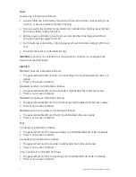
Page 19: ...ral Disable button and then press the Sounder Fault Disable Test button Sounders can only be disabled when the control panel is in standby Disabled sounders are indicated as follows The general Disable LED is steady The Sounder Fault Disable Test LED is steady To enable the sounders press the general Disable button and then press the Sounder Fault Disable Test button again WARNING Disabled sounder...

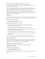
Page 20: ...ing press the general Disable button and then press the Fire Routing Start button again WARNING Disabled fire routing does not indicate a fault or operate if there is a fire alarm Disabling expansion modules or enabling disabled expansion modules To disable expansion modules press the general Disable button and then press Enter Disabled expansion modules are indicated as follows The general Disabl...

Page 21: ... call point each time Quarterly maintenance Contact your installation or maintenance contractor to carry out a quarterly inspection of the fire alarm system This inspection must test at least one device per zone and verify that the control panel responds to all fault and alarm events The control panel power supply and battery voltage should be checked Batteries with low voltage must be replaced fo...

Page 22: ...battery indication Battery supply and battery fuse faults are indicated by a flashing Supply Fault LED If this LED flashes check the following That the battery cables are in good condition That the battery cables are connected securely and correctly at the battery and at the control panel PCB That the battery voltage is greater than 19 6 V If the cables are in good condition and all connections ar...

Page 23: ... 7 8 Output to fire alarm devices 7 9 1 Output to fire alarm routing equipment 1 7 11 Delays to outputs 7 13 Alarm counter 2 8 4 Total loss of the power supply 10 Test condition 11 Standardised input output interface 1 Excluding two zone models 2 Dutch models only European standards for electrical safety and electromagnetic compatibility These control panels have been designed in accordance with t...

Page 24: ...20 Kilsen KFP CF Series Operation Manual ...

Reviews: