A–18
LM10 MOTOR PROTECTION SYSTEM – INSTRUCTION MANUAL
LM10 AND ALLEN-BRADLEY SLC500 VIA DEVICENET™
CHAPTER A:
Z
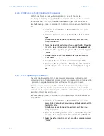
Once the DeviceNet connection (consisting of the 1747-SDN
Scanner card, 1770-KFD, and LM10 relay) is complete, click the
Online
icon and upload the network.
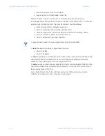
Scanning for the Nodes on the Network will start. Using the EDS Wizard, add the LM10
to the hardware list in RSNetworx. A sample screen of RSNetworx with 3 nodes is
shown below.
•
LM10 Motor Protection System: MAC ID 09
•
1770-KFD: MAC ID 62
•
1747SDN Scanner Card: MAC ID 63
FIGURE A–5: Example RSNetworx Screen
A.3.5 Changing the Mode of Operation
Use the following procedure to change the mode of operation.
Z
In RSLogix 500 open the Force File O0 Output.
Summary of Contents for LM10
Page 6: ...1 IV LM10 MOTOR PROTECTION SYSTEM INSTRUCTION MANUAL TABLE OF CONTENTS ...
Page 18: ...1 12 LM10 MOTOR PROTECTION SYSTEM INSTRUCTION MANUAL SPECIFICATIONS CHAPTER 1 INTRODUCTION ...
Page 70: ...5 64 LM10 MOTOR PROTECTION SYSTEM INSTRUCTION MANUAL SERIAL PORT CHAPTER 5 COMMUNICATIONS ...
Page 74: ...6 68 LM10 MOTOR PROTECTION SYSTEM INSTRUCTION MANUAL WARRANTY CHAPTER 6 MISCELLANEOUS ...
Page 106: ...I 4 LM10 MOTOR PROTECTION SYSTEM INSTRUCTION MANUAL INDEX ...


