background image

2272728-100

REV    0

g

GE Medical Systems

4/4

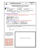
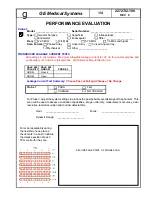
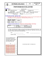
SECURE PAGE PRINT OF

PROBE NOISE LEVEL

SCAN HERE

Probe 4 

(cont'd)

:

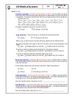
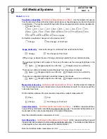
Noise Level.


QA Reference Manual Section 4-2 Step 5.

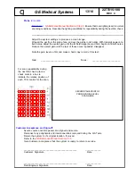
  Ensure that room lighting is set to normal

scanning conditions.  Describe the lighting conditions for repeatability during the next QA check.

___________________________________________________________________________________________________________

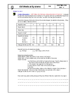
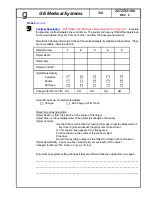
Adjust the system settings to produces a clean image.
Wipe all the gel from the probe face, and set the probe in its holder. With transmit power at a fixed
value, adjust the overall gain, until the far field image (beyond 3cm) begins to fill with noise. Reduce
the overall gain until the last of those noise “speckles” disappear.

Note the gain level on film and make a hard copy record of this test.

Gain:      ________________________                Focus :      ________________________

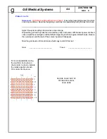
For scan repeatability during
the next QA check, place a
check mark in a box to indicate
the relative position of each
TCG control for the scan.

Summary of Contents for LOGIQ 200

Page 1: ...Revision 0 2278812 100 Technical Publications GE Medical Systems LOGIQ 200 and LOGIQ 200 PRO Quality Assurance Manual Copyright 2000byGeneralElectricCompany OperatingDocumentation g ...

Page 2: ...l Systems Telex 3797371 P O Box 414 Milwaukee Wisconsin 53201 U S A Asia Pacific Latin America North America GE Medical Systems Europe Telex 695277 283 rue de la Miniére BP34 78533 BUC Cedex GE Medical Systems g ...

Page 3: ...100 4 Pages Probe 6 2272730 100 4 Pages Probe 7 2272732 100 4 Pages Probe 8 2272733 100 4 Pages Probe 9 2272735 100 4 Pages TAB 4 QA Reference Manual 2262684 100 30 Pages Probe ID List 1 Page TAB 5 System Display Format 2 Pages TAB 6 Section 4 Service Manuals 20 Pages TAB 7 Section 2 Service Manuals 75 Pages TAB 8 Filling out the ACR Forms 5 Pages TAB 9 ACR Section G Quality Control 3 Pages ACR Se...

Page 4: ......

Page 5: ...tion process consists of three parts which must be completed successfully in order to receive accreditation Application requests credentials of physicians and sonographer personnel Quality Control Evaluation requests information about ultrasound quality control Clinical Image Evaluation requests specific types of normal ultrasound exams plus normal and abnormal exams for vascular accreditation QUA...

Page 6: ...ct a phantom from current commercially available units 2 Test Frequency QA tests should be done at least semiannually for each scanner as part of the quality assurance program for the site Test results must be documented so that trends in equipment performance can be identified and appropriate corrective action taken 3 Transducers On an ongoing basis tests should be done using two probes commonly ...

Page 7: ...n How I envision this to work All forms are electronic and will be on a CD FE opens up System QA Procedure on field laptop FE performs appropriate checks and tests in the System QA Procedure FE makes necessary entries on the electronic form FE makes required hard copy images At the completion of the System QA Procedure FE prints out the procedure attaches the hard copy images in the appropriate pl...

Page 8: ......

Page 9: ...45222CS Gen Purp 3 5 MHz Curved Linear ERB H45202ER Endorectal 5 7 5 MHz Curved Linear 3Cb H45202WB Gen Purp 3 5 MHz Curved Linear LH H46022LH Superficial 7 5 MHz Linear LE H46022LE Gen Purp 5 7 5 MHz Linear LI H46022LI Intraoperative 7 5 MHz Linear LT H46022LT Intraoperative 7 5 MHz Linear LB H46022LB Gen Purp 3 5 MHz Linear LD H45202LD Intraoperative 3 5 MHz Linear 10L H45202LM Gen Purp 5 7 5 MH...

Page 10: ...05 23 00 MAC Page 2 of 2 ...

Page 11: ... frequently should be listed as transducer number 1 and 2 Use the separate documents provided to document the remaining transducers Transducer 1 Model ________________________ Serial Number ______________________________ Type General Purpose Superficial Intraoperative Endorectal Endovaginal Other _____________________ Freq 2 3 5 MHz 3 5 MHz 5 7 5 MHz 7 5 MHz and higher Scan Format Phased Array Lin...

Page 12: ...eral purpose and endocavitary or 50 uA for surgical probes QA Reference Manual Section 3 9 DALE 600 DALE 600 POLARITY GND SW PROBE 1 PROBE 2 NORM Closed NORM Open LINE VOLTAGE TEST System OFF ______________VAC__ System ON ________________VAC__ LINE CURRENT TEST optional System OFF ______________Amps_ System ON ________________Amps_ OUTLET WIRING TEST QA Reference Manual Section 3 3 If correct proc...

Page 13: ...aper YES NO Overall Electrical Safety and Cleanliness CHANGE NO CHANGE All safety problems must be rectified before the system can be returned to service or before ACR Accreditation submittal Comments _____________________________________________________________________ _______________________________________________________________________________ _________________________________________________...

Page 14: ...ting Dynamic Range Dynamic Range Dynamic Range Comments _____________________________________________________________________ _______________________________________________________________________________ _______________________________________________________________________________ NOTE Refer to theLOGIQa200 orLOGIQ200PROUserManualformoreinformationonsystemoperation Reference is 0 voltage for t...

Page 15: ...e customer specifications Look at the gray bar test pattern on the left side of the viewing monitor Count the number of distinct gray bar steps on the viewing monitor Then count the number of steps visualized in the Gray bar on the hard copy image Circle the number of steps if any that are missing on the hard copy Circle the number of steps if any that are missing on the hard copy Check the one bo...

Page 16: ...onstrate errors in excess of 10 if you are establishing a baseline or comparing to previous results Probe 1 For Probe 1 adjust the system settings to produce the best possible overall image of the phantom This scan will be used to assess penetration capabilities image uniformity measurement accuracy axial resolution lateral resolution and contrast detectability SECURE PAGE PRINT OF PROBE 1 SCAN Fo...

Page 17: ... is Less than 3 0 3 0 3 5 4 0 4 5 5 0 5 5 6 0 6 5 7 0 7 5 8 0 8 5 9 0 9 5 10 0 10 5 11 0 11 5 12 0 12 5 13 0 13 5 14 0 15 0 1 16 0 or higher Did system penetration change since the previous test Change No Change or First Test Image Uniformity Assess the image for uniformity from near field to far field Change No Change or First Test With your eye evaluate the scan for image uniformity against the ...

Page 18: ... from the skin line to the center of the object Object Size is the overall diameter of the object all should be the same Object Contrast Use the Echo Level function by freezing the image Press the Measurement key three 3 times to assess the gray scale contrast level A 3 cm square box appears in the image area Position the box in the center of the contrast object Press Set Record the resulting numb...

Page 19: ...________ Adjust the system settings to produces a clean image Wipe all the gel from the probe face and set the probe in its holder With transmit power at a fixed value adjust the overall gain until the far field image beyond 3cm begins to fill with noise Reduce the overall gain until the last of those noise speckles disappear Note the gain level on film and make a hard copy record of this test Gai...

Page 20: ...15 0 16 0 or higher Did system penetration change since the previous test Change No Change or First Test Probe 2 For Probe 2 adjust the system settings to produce the best possible overall image of the phantom This scan will be used to assess penetration capabilities image uniformity measurement accuracy axial resolution lateral resolution and contrast detectability SECURE PAGE PRINT OF PROBE 2 SC...

Page 21: ... Section 4 2 Step 3 Use the calipers to measure from the vertical pin closest to the skin line to the pin furthermost in depth Do the same with the horizontal row of pins Did the distance between the pins measured equal the e caliper measurement Pass Fail Change No Change or First Test Lateral Resolution QA Reference Manual Section 4 2 Step 1 LATERAL resolution defines how well the system probe ca...

Page 22: ... line to the center of the object Object Size is the overalldiameter of the object all should be the same Object Contrast Use the Echo Level function by freezing the image Press the Measurement key three 3 times to assess the gray scale contrast level A 3 cm square box appears in the image area Position the box in the center of the contrast object Press Set Record the resulting number as the Objec...

Page 23: ...e Reduce the overall gain until the last of those noise speckles disappear Note the gain level on film and make a hard copy record of this test Gain ________________________ Focus ________________________ For scan repeatability during the next QA check place a check mark in a box to indicate the relative position of each TCG control for the scan Customer Acceptance and Sign off Assure covers and s...

Page 24: ...er a catastrophic system failure PRESETS All system presets can be saved on a 128 Mbyte MOD through the SETUP UTILITY Menu Press the SETUP MENU Key Arrow down to USER UTILITY and press SET In the USER UTILITY Menu ensure that a MOD has been formatted using Media Initialize Perform thye following procedures Preset Data Backup OB User Table Backup OB Trend Data Backup Label and date the MOD accordin...

Page 25: ...arameter pages Remember Some pages may require two or more prints due to each applications presets and then for each probe attached Use the following items as a check list of what menus were printed General System Setup User OB Table Sub menu Probe Parameter 1 Setup Preset 1 Probe 1 Probe 2 Preset 2 Probe 1 Probe 2 Probe Parameter 2 Setup Preset 1 Probe 1 Probe 2 Preset 2 Probe 1 Probe 2 Image Dis...

Page 26: ...nction Sector Path B Mode Function BPHV B Mode X Y Memory MVP Hardware B Mode Cine B Mode Function M Mode Function B Mode Cine MST M Mode Function System D RAM MSTE Keyboard Keyboard PIOP PIOP Monitor Monitor Power Supply Power Supply ROM Version Comments _____________________________________________________________________ __________________________________________________________________________...

Page 27: ...45222CS Gen Purp 3 5 MHz Curved Linear ERB H45202ER Endorectal 5 7 5 MHz Curved Linear 3Cb H45202WB Gen Purp 3 5 MHz Curved Linear LH H46022LH Superficial 7 5 MHz Linear LE H46022LE Gen Purp 5 7 5 MHz Linear LI H46022LI Intraoperative 7 5 MHz Linear LT H46022LT Intraoperative 7 5 MHz Linear LB H46022LB Gen Purp 3 5 MHz Linear LD H45202LD Intraoperative 3 5 MHz Linear 10L H45202LM Gen Purp 5 7 5 MH...

Page 28: ...05 23 00 MAC Page 2 of 2 ...

Page 29: ...ngs in micro amps Maximum allowable leakage current is 100 uA for general purpose and endocavitary or 50 uA for surgical probes QA Reference Manual Section 3 9 DALE 600 DALE 600 POLARITY GND SW PROBE 3 NORM Closed NORM Open For Probe 3 adjust the system settings to produce the best possible overall image of the phantom This scan will be used to assess penetration capabilities image uniformity meas...

Page 30: ...ss Than 3 0 3 0 3 5 4 0 4 5 5 0 5 5 6 0 6 5 7 0 7 5 8 0 8 5 9 0 9 5 10 0 10 5 11 0 11 5 12 0 12 5 13 0 13 5 14 0 15 0 16 0 or higher Did system penetration change since the previous test Change No Change or First Test Image Uniformity Assess the image for uniformity from near field to far field Change No Change or First Test With your eye evaluate the scan for image uniformity against the three in...

Page 31: ...kin line to the center of the object Object Size is the overalldiameter of the object all should be the same Object Contrast UsetheEchoLevelfunctionbyFreezingtheimage PresstheMeasurement key three 3 times to assess the gray scale contrast level A 3 cm square box appears in the image area Position the box in the center of the contrast object Press Set Record the resulting number as the Object Contr...

Page 32: ...______ Adjust the system settings to produces a clean image Wipe all the gel from the probe face and set the probe in its holder With transmit power at a fixed value adjusttheoverallgain untilthefarfieldimage beyond3cm beginstofillwithnoise Reduce the overall gain until the last of those noise speckles disappear Note the gain level on film and make a hard copy record of this test Gain ____________...

Page 33: ...ngs in micro amps Maximum allowable leakage current is 100 uA for general purpose and endocavitary or 50 uA for surgical probes QA Reference Manual Section 3 9 DALE 600 DALE 600 POLARITY GND SW PROBE 3 NORM Closed NORM Open For Probe 3 adjust the system settings to produce the best possible overall image of the phantom This scan will be used to assess penetration capabilities image uniformity meas...

Page 34: ...ss Than 3 0 3 0 3 5 4 0 4 5 5 0 5 5 6 0 6 5 7 0 7 5 8 0 8 5 9 0 9 5 10 0 10 5 11 0 11 5 12 0 12 5 13 0 13 5 14 0 15 0 16 0 or higher Did system penetration change since the previous test Change No Change or First Test Image Uniformity Assess the image for uniformity from near field to far field Change No Change or First Test With your eye evaluate the scan for image uniformity against the three in...

Page 35: ...kin line to the center of the object Object Size is the overalldiameter of the object all should be the same Object Contrast UsetheEchoLevelfunctionbyFreezingtheimage PresstheMeasurement key three 3 times to assess the gray scale contrast level A 3 cm square box appears in the image area Position the box in the center of the contrast object Press Set Record the resulting number as the Object Contr...

Page 36: ...______ Adjust the system settings to produces a clean image Wipe all the gel from the probe face and set the probe in its holder With transmit power at a fixed value adjusttheoverallgain untilthefarfieldimage beyond3cm beginstofillwithnoise Reduce the overall gain until the last of those noise speckles disappear Note the gain level on film and make a hard copy record of this test Gain ____________...

Page 37: ...ngs in micro amps Maximum allowable leakage current is 100 uA for general purpose and endocavitary or 50 uA for surgical probes QA Reference Manual Section 3 9 DALE 600 DALE 600 POLARITY GND SW PROBE 3 NORM Closed NORM Open For Probe 3 adjust the system settings to produce the best possible overall image of the phantom This scan will be used to assess penetration capabilities image uniformity meas...

Page 38: ...ss Than 3 0 3 0 3 5 4 0 4 5 5 0 5 5 6 0 6 5 7 0 7 5 8 0 8 5 9 0 9 5 10 0 10 5 11 0 11 5 12 0 12 5 13 0 13 5 14 0 15 0 16 0 or higher Did system penetration change since the previous test Change No Change or First Test Image Uniformity Assess the image for uniformity from near field to far field Change No Change or First Test With your eye evaluate the scan for image uniformity against the three in...

Page 39: ...kin line to the center of the object Object Size is the overalldiameter of the object all should be the same Object Contrast UsetheEchoLevelfunctionbyFreezingtheimage PresstheMeasurement key three 3 times to assess the gray scale contrast level A 3 cm square box appears in the image area Position the box in the center of the contrast object Press Set Record the resulting number as the Object Contr...

Page 40: ...______ Adjust the system settings to produces a clean image Wipe all the gel from the probe face and set the probe in its holder With transmit power at a fixed value adjusttheoverallgain untilthefarfieldimage beyond3cm beginstofillwithnoise Reduce the overall gain until the last of those noise speckles disappear Note the gain level on film and make a hard copy record of this test Gain ____________...

Page 41: ...ngs in micro amps Maximum allowable leakage current is 100 uA for general purpose and endocavitary or 50 uA for surgical probes QA Reference Manual Section 3 9 DALE 600 DALE 600 POLARITY GND SW PROBE 3 NORM Closed NORM Open For Probe 3 adjust the system settings to produce the best possible overall image of the phantom This scan will be used to assess penetration capabilities image uniformity meas...

Page 42: ...ss Than 3 0 3 0 3 5 4 0 4 5 5 0 5 5 6 0 6 5 7 0 7 5 8 0 8 5 9 0 9 5 10 0 10 5 11 0 11 5 12 0 12 5 13 0 13 5 14 0 15 0 16 0 or higher Did system penetration change since the previous test Change No Change or First Test Image Uniformity Assess the image for uniformity from near field to far field Change No Change or First Test With your eye evaluate the scan for image uniformity against the three in...

Page 43: ...kin line to the center of the object Object Size is the overalldiameter of the object all should be the same Object Contrast UsetheEchoLevelfunctionbyFreezingtheimage PresstheMeasurement key three 3 times to assess the gray scale contrast level A 3 cm square box appears in the image area Position the box in the center of the contrast object Press Set Record the resulting number as the Object Contr...

Page 44: ...______ Adjust the system settings to produces a clean image Wipe all the gel from the probe face and set the probe in its holder With transmit power at a fixed value adjusttheoverallgain untilthefarfieldimage beyond3cm beginstofillwithnoise Reduce the overall gain until the last of those noise speckles disappear Note the gain level on film and make a hard copy record of this test Gain ____________...

Page 45: ...ngs in micro amps Maximum allowable leakage current is 100 uA for general purpose and endocavitary or 50 uA for surgical probes QA Reference Manual Section 3 9 DALE 600 DALE 600 POLARITY GND SW PROBE 3 NORM Closed NORM Open For Probe 3 adjust the system settings to produce the best possible overall image of the phantom This scan will be used to assess penetration capabilities image uniformity meas...

Page 46: ...ss Than 3 0 3 0 3 5 4 0 4 5 5 0 5 5 6 0 6 5 7 0 7 5 8 0 8 5 9 0 9 5 10 0 10 5 11 0 11 5 12 0 12 5 13 0 13 5 14 0 15 0 16 0 or higher Did system penetration change since the previous test Change No Change or First Test Image Uniformity Assess the image for uniformity from near field to far field Change No Change or First Test With your eye evaluate the scan for image uniformity against the three in...

Page 47: ...kin line to the center of the object Object Size is the overalldiameter of the object all should be the same Object Contrast UsetheEchoLevelfunctionbyFreezingtheimage PresstheMeasurement key three 3 times to assess the gray scale contrast level A 3 cm square box appears in the image area Position the box in the center of the contrast object Press Set Record the resulting number as the Object Contr...

Page 48: ...______ Adjust the system settings to produces a clean image Wipe all the gel from the probe face and set the probe in its holder With transmit power at a fixed value adjusttheoverallgain untilthefarfieldimage beyond3cm beginstofillwithnoise Reduce the overall gain until the last of those noise speckles disappear Note the gain level on film and make a hard copy record of this test Gain ____________...

Page 49: ...ngs in micro amps Maximum allowable leakage current is 100 uA for general purpose and endocavitary or 50 uA for surgical probes QA Reference Manual Section 3 9 DALE 600 DALE 600 POLARITY GND SW PROBE 3 NORM Closed NORM Open For Probe 3 adjust the system settings to produce the best possible overall image of the phantom This scan will be used to assess penetration capabilities image uniformity meas...

Page 50: ...ss Than 3 0 3 0 3 5 4 0 4 5 5 0 5 5 6 0 6 5 7 0 7 5 8 0 8 5 9 0 9 5 10 0 10 5 11 0 11 5 12 0 12 5 13 0 13 5 14 0 15 0 16 0 or higher Did system penetration change since the previous test Change No Change or First Test Image Uniformity Assess the image for uniformity from near field to far field Change No Change or First Test With your eye evaluate the scan for image uniformity against the three in...

Page 51: ...kin line to the center of the object Object Size is the overalldiameter of the object all should be the same Object Contrast UsetheEchoLevelfunctionbyFreezingtheimage PresstheMeasurement key three 3 times to assess the gray scale contrast level A 3 cm square box appears in the image area Position the box in the center of the contrast object Press Set Record the resulting number as the Object Contr...

Page 52: ...______ Adjust the system settings to produces a clean image Wipe all the gel from the probe face and set the probe in its holder With transmit power at a fixed value adjusttheoverallgain untilthefarfieldimage beyond3cm beginstofillwithnoise Reduce the overall gain until the last of those noise speckles disappear Note the gain level on film and make a hard copy record of this test Gain ____________...

Page 53: ...ngs in micro amps Maximum allowable leakage current is 100 uA for general purpose and endocavitary or 50 uA for surgical probes QA Reference Manual Section 3 9 DALE 600 DALE 600 POLARITY GND SW PROBE 3 NORM Closed NORM Open For Probe 3 adjust the system settings to produce the best possible overall image of the phantom This scan will be used to assess penetration capabilities image uniformity meas...

Page 54: ...ss Than 3 0 3 0 3 5 4 0 4 5 5 0 5 5 6 0 6 5 7 0 7 5 8 0 8 5 9 0 9 5 10 0 10 5 11 0 11 5 12 0 12 5 13 0 13 5 14 0 15 0 16 0 or higher Did system penetration change since the previous test Change No Change or First Test Image Uniformity Assess the image for uniformity from near field to far field Change No Change or First Test With your eye evaluate the scan for image uniformity against the three in...

Page 55: ...kin line to the center of the object Object Size is the overalldiameter of the object all should be the same Object Contrast UsetheEchoLevelfunctionbyFreezingtheimage PresstheMeasurement key three 3 times to assess the gray scale contrast level A 3 cm square box appears in the image area Position the box in the center of the contrast object Press Set Record the resulting number as the Object Contr...

Page 56: ...______ Adjust the system settings to produces a clean image Wipe all the gel from the probe face and set the probe in its holder With transmit power at a fixed value adjusttheoverallgain untilthefarfieldimage beyond3cm beginstofillwithnoise Reduce the overall gain until the last of those noise speckles disappear Note the gain level on film and make a hard copy record of this test Gain ____________...

Page 57: ...Revision 1 2262684 100 Technical Publications GEMedicalSystems Ultrasound Quality Assurance Reference Manual Copyright 2000 by General Electric Company Operating Documentation g ...

Page 58: ...l Systems Telex 3797371 P O Box 414 Milwaukee Wisconsin 53201 U S A Asia Pacific Latin America North America GE Medical Systems Europe Telex 695277 283 rue de la Miniére BP34 78533 BUC Cedex GE Medical Systems g ...

Page 59: ...F EFFECTIVE PAGES PAGE REVISION PAGE REVISION PAGE REVISION NUMBER NUMBER NUMBER NUMBER NUMBER NUMBER Title Page 1 A and B 1 Chapter 1 1 Chapter 2 1 Chapter 3 1 Chapter 4 1 Please verify that you are using the latest revision of this document Information pertain ing to this document is maintained on GPC Global Product Configuration If you do not know how to use GPC contact your Manager or the Nati...

Page 60: ...B GE MEDICAL SYSTEMS ULTRASOUND QUALITY ASSURANCE REFERENCE MANUAL REV 1 2262684 100 This page intentionally left blank ...

Page 61: ... 1 2 Contents The material used in this manual is a culmination of information developed by GEMS Ultrasound Any comments or questions regarding the content of this document should be directed to the Ultrasound Documentation group This manual consists of 1 2 1 QA Procedure Instruction Details The QATesting Procedure is intended to be used as a steering guide to perform the needed PM checks The proc...

Page 62: ...ing the equipment 1 4 Probe Cleaning Before cleaning the probes refer to the Operator s Manuals for cleaning and disinfecting instructions Failure to follow these instruction will likely result in damage to probe materials and performance To remove coupling gel from a probe wipe the lens with a soft cloth warm water and mild soap To clean other surfaces use warm water and mild soap with a soft spo...

Page 63: ... the sterilization equipment and gas supplier NOTE Do not use process cycles that exceed 60 degrees C or pressures that vary from normal atmosphere CAUTION Ultrasound transducers are easily damaged by improper handling storage or cleaning Failure to follow OEM Specifications and Precautions can result in equipmentdamageandreplacementexpenseliability Neverimmersethetransducer connector or probe ada...

Page 64: ...1 4 GE MEDICAL SYSTEMS ULTRASOUND QUALITY ASSURANCE REFERENCE MANUAL REV 1 2262684 100 This Page Intentionally Left Blank ...

Page 65: ...n Use the check boxes to note all options peripherals or accessories attached to the ultrasound system 2 4 Test Equipment Fill in the following for the test equipment used during the QA tests Leakage Current Tester Multimeter Gray Scale Phantom indicate the db range of the phantom if available If any test equipment is not used indicate with N A on the procedure Fill in the Field Engineer Name and ...

Page 66: ...hecks on transducers 1 and 2 2 8 Physical Inspection Cleaning Indicate YES NO or N A for the items in the table on the middle of the page that are to be inspected and or cleaned Consider the following steps during inspection and cleaning 1 Wipe Down Exterior Console Note the location of any controls that are not reset on boot Use appropriate cleansers and materials to clean the CRT keyboards opera...

Page 67: ...ect any peripherals and interconnections removed 3 Assure covers and side panels are aligned and secure 4 If possible return the system to its original location if it was moved 2 8 Physical Inspection Cleaning cont d 8 Re seat PC Boards in Card Rack Apply Power to the system and verify operation of all internal fans 9 Reconnect Probes to System 10 Note any performance or service related issues on ...

Page 68: ... or not applicable 2 12 Gray Scale Test TThe gray scale test is not intended to set up the camera printer or peripherals to the test pattern Ensure that the monitor and photography are set up to the customer specifications Look at the gray bar test pattern on the left side of the viewing monitor Count the number of distinct gray bar steps on the viewing monitor Then count the number of steps visua...

Page 69: ...ects the image be made 1 Check overall image uniformity from near field to far field Change or No Change 2 Check average brightness at the edges of the scan compared to the middle Check either Agree Disagree slight non uniformity or Disagree major non uniformity 3 Check that there are no vertical or radially oriented lines from array dropout Check either Agree Disagree slight non uniformity or Dis...

Page 70: ...e Targets The point is not how any ONE of them looks but how well defined they are from each other and from the background material Under each object number record the following information for five of the contrast targets Object Depth in centimeters Object Size in millimeters Object Contrast level Object Detectability Complete Partial or Not Seen Change for the worse Yes or No If there are less t...

Page 71: ...les used This will include the 22 pages of the procedure pages per additional probe and 4 pages of the ACR Ultrasound Accreditation Application Forms Section G H Also print out any additional probe testing procedure forms completed 4 Attach all hard copy prints to the appropriate places in the QA Test Procedure and gain customer acceptance with the appropriate signature on the last page of the pro...

Page 72: ...nd monitor alignment Press CONTROL SB to display the grid test pattern Answer the two questions Yes or No about location and alignment on the QA Testing Procedure 2 19 Borderline Borderline displays a test pattern on the monitor that can be used to verify that the CRT aspect ratio is 4 3 Press CONTROL SB to display the test pattern Use electronic calipers or a ruler to measure the horizontal and v...

Page 73: ...ndle soiled or contaminated probes and other components that have been in patient contact Follow appropriate cleaning and disinfecting procedures before handling the equipment 3 2 GEMS Leakage Current Limits The following limits are summarized for UL 544 UL2601 1 and IEC 601 1 Medical Equipment Safety Standards These limits are GEMS standards and in some cases are lower than the above standards li...

Page 74: ... NOTE No outlet tester can detect the condition where the white neutral wire and the green grounding wire are reversed If later tests indicate high leakage currents this should be suspected as a possible cause and the outlet wiring should be visually inspected Illustration 3 1 Outlet Test Illustration 3 2 Outlet Test Dale 600 3 2 3 Type CF Applied Part Leakage Current Limits Surgical Transducers a...

Page 75: ...ipment during this test The Dale 600 measures line cord resistance from the third pin of the attachment plug to the meter s Chassis Cable clamp Test the grounding continuity of the system to all exposed metal parts in accordance with the IEC 601 1 1 procedure as above See Illustration 3 4 Refer to the Dale 600 Instruction Manual for meter self tests and operation Record measured resistance of the ...

Page 76: ...ale 600 always use the CHASSIS selection of the external chassis function switch This requires the ground clip lead and changing the meters switches in accordance with the IEC 601 1 1 See Illustration 2 4 Refer to the Dale 600 Instruction Manual for meter self test and operation Record the highest leakage current measured on the appropriate form When using the Microguard or a similar test instrume...

Page 77: ...perated to find the worst case condition Record the leakage measured on the appropriate form The maximum isolated patient lead isolation leakage is 10mA The Dale 600 provides five snap type ECG buttons for testing patient leads Snap on all patient leads to the meter and assure that the ground clip is connected to the system s ground terminal See Illustration 3 7 Select the meter s LEAD GND functio...

Page 78: ...ion Test The Dale 600 provides a method for testing probes independently from the system The meter utilizes a probe adapter to apply a test potential commonly to all connector pins See Illustration 3 8 The probe s imaging area is immersed in a saline solution along with a grounding probe from the meter to complete the current path Saline solution is a mixture of water and salt The salt adds a free...

Page 79: ...the ISO TEST switch is depressed Illustration3 8 TransducerSourceLeakage IsolationTestwithDale600 NOTE Contact Dale Technology at 914 741 5000 for specialty Probe Adapters needs Probe and meter lead are placed in saline solution Generic Transducer Leakage Current Check without probe adapters In the absence of probe adapters use the following setup to measure the current that would flow to ground t...

Page 80: ...3 8 GE MEDICAL SYSTEMS ULTRASOUND QUALITY ASSURANCE REFERENCE MANUAL REV 1 2262684 100 This Page Intentionally Left Blank ...

Page 81: ...edure to be performed following re assembly and rework Should any test fail to be within published limits or if results are noticed to be non typical it is required to troubleshoot the cause Following identification and correction of the fault or cause a complete retest of the system for electrical safety is required Use the Electrical Safety Data table on the QA Procedure to record the values for...

Page 82: ...2 of the maximum penetration Adjust the TGC Image Gain Focus to optimize the image Zoom in on this group if necessary to display the smallest separation visible Make a hard copy ALTERNATIVE If a lateral resolution group is not available on your phantom freeze the image and take a measurement of one of the 1mm target wires nearest the focus of the transducer at approximately 1 2 total penetration d...

Page 83: ...ruments and all phantoms try to approximate this and may not generate exact results during baseline tests Illustration 4 2 Measurements ACQUISITION The biggest variable is phantom temperature which may demonstrate errors well in excess of 10 Adjust the displayed depth so that the maximum number of pins are visible in the same axis as the probe vertical Position the probe so that this row of dots i...

Page 84: ...n for returning echoes in the range of a few micro volts By choosing the correct application of an individual probe and the best system settings for the application the technician is capable of maximizing the ratio of true signal to noise However Image degradation can occur due excess noise that can come from many sources While this goes beyond the scope of this document Noise level verification o...

Page 85: ...ese are provided to quantify the dynamic range of the instrument as it is spread over the grayscale boundaries of the scan converter Over time variances in system performance or poor imaging can be quickly noted ACQUISITION Adjust the Depth Master Gain TGC and Transmit Power to produce the best shot of ALL the Grayscale Targets in one view Freeze the view that best demonstrates the separation betw...

Page 86: ...dure Present the PM QA Procedure and any Films Hard Copies of QA Images to the Customer Reminder the customer of the need to reatin these records for comparison to future QA procedures and for ACR accreditation Review any outstanding service issues and schedule service Store the customer copy in the Customer Site Log If applicable ...

Page 87: ...LOGIQ α200 ...

Page 88: ...LOGIQ 200 PRO ...

Page 89: ...APTER 4 FUNCTIONAL CHECKS TABLE OF CONTENTS SECTION TITLE PAGE 4 1 INTRODUCTION 4 3 4 1 1 Required Equipment 4 3 4 2 FUNCTIONAL CHECK PROCEDURES 4 3 4 2 1 Basic Controls 4 3 4 2 2 M Mode Check 4 5 4 3 SMPS ADJUSTMENTS 4 7 4 3 1 SMPS Assy Access 4 7 4 3 2 SMPS Adjustment Procedure 4 9 ...

Page 90: ...GE MEDICAL SYSTEMS LOGIQ α200 SERVICE MANUAL 2138853 FUNCTIONAL CHECKS 4 2 REV 0 This page is left blank intentionally ...

Page 91: ...select another gray scale Map The gray scale adjusts to each new Map selected 5 Press Dyn Range Arrow up or down key At lower Dynamic Range settings image speckle fades and prominent objects in the display are more pronounced from the background image 6 Rotate Depth knob The depth of image should be increased decreased 7 Slide TGC potentiometers pots Image grows darker or brighter at depth equival...

Page 92: ...MANUAL 2138853 FUNCTIONAL CHECKS 4 4 REV 3 4 2 1 Basic Controls Continued ÇÇ ÇÇ ÇÇ ÇÇ ÇÇ ÇÇ ÇÇ ÇÇ ÇÇ ÇÇ ÇÇ ÇÇ ÇÇ ÇÇ ÇÇ 0 cm 1 cm 5 cm 10 cm ÇÇÇÇÇÇÇÇÇÇÇÇÇÇÇÇÇÇÇÇÇÇÇ Map1 Cine Gauge FOV GE FA EE Category B MODE DISPLAY SCREEN ILLUSTRATION 4 1 ...

Page 93: ...he CRT monitor 14 Rotate B M Gain knob The M timeline should get brighter with CW rotation and darker with CCW 15 Press Dyn Range Arrow up or down key Dynamic Range affects grays and the last added scan mode to adjust the basic B M must be off Turn Dynamic Range down to increase contrast turn up to soften 16 Press Sweep Speed key Press it again to exit The timeline speed should increase to 4 secon...

Page 94: ... ÇÇ ÇÇ ÇÇ ÇÇ ÇÇ ÇÇ ÇÇ Map1 FOV ÇÇÇÇÇÇÇÇÇÇÇÇÇÇÇÇÇÇ ÇÇ ÇÇ ÇÇ ÇÇ ÇÇ ÇÇ ÇÇ ÇÇ ÇÇ ÇÇ ÇÇ ÇÇ ÇÇ M GE Cine Gauge Cine Gauge FA EE Category M MODE DISPLAY SCREEN ILLUSTRATION 4 2 Note You can select several types of display formats by using the Setup Menu For the Preset Menu refer to Customizing Your System in the LOGIQ α200 User Manual ...

Page 95: ...outlet conforms to the proper power line standards Refer to Chapter 2 Installation Note If the adjustment pot is turned to far clockwise the SMPS output shuts down to protect the circuits against the over voltage In that case power the LOGIQ α200 OFF and turn the pot counterclockwise all the way Then power it ON and try to adjust the SMPS again The SMPS Assy is in the bottom of the LOGIQ α200 as s...

Page 96: ... the four screw caps and unscrew the screws to remove the Right Cover as shown in the ILLUSTRATION 4 4 Right Cover RIGHT COVER REMOVAL ILLUSTRATION 4 4 3 Remove the four screw caps and unscrew the screws to remove the Rear Cover as shown in the ILLUSTRATION 4 5 ÉÉ ÉÉ ÉÉ ÉÉ ÉÉ Rear Cover REAR COVER REMOVAL ILLUSTRATION 4 5 ...

Page 97: ... 15V on ESP BD ASSY TP3 Ground on ESP BD ASSY 1 on SMPS ASSY See ILLUSTRATION 4 6 5V for Analog Digital V 5 5V on ESP BD ASSY TP3 Ground on ESP BD ASSY 2 on SMPS ASSY See ILLUSTRATION 4 6 12 for Monitor B 12V on Monitor Input Connector GND on Monitor Input Connector 3 on SMPS ASSY See ILLUSTRATION 4 6 5V for Digital TP 602 5V on MST BD ASSY TP 601 GND on MST BD ASSY 4 on SMPS ASSY See ILLUSTRATION...

Page 98: ...FUNCTIONAL CHECKS 4 10 REV 0 4 3 2 SMPS Adjustment Procedure Continued ÉÉÉ ÉÉÉ ÉÉÉ ÉÉÉ ÉÉÉ 1 Adjustment Point for 5V 15V SMPS 2 Adjustment Point for 5V SMPS 3 Adjustment Point for 12V SMPS 4 Adjustment Point for 5V SMPS 1 2 3 4 SMPS ASSY ILLUSTRATION 4 6 ...

Page 99: ...ap key to select another gray scale Map The gray scale adjusts to each new Map selected 5 Press Dyn Range Arrow up or down key At lower Dynamic Range settings image speckle fades and prominent objects in the display are more pronounced from the background image 6 Rotate Depth knob The depth of image should be increased decreased 7 Slide TGC potentiometers pots Image grows darker or brighter at dep...

Page 100: ...GE MEDICAL SYSTEMS LOGIQ 200 PRO Series SERVICE MANUAL 2235374 FUNCTIONAL CHECKS 4 4 REV 0 4 2 1 Basic Controls Continued Map1 Cine Gauge GE B Mode B MODE DISPLAY SCREEN ILLUSTRATION 4 1 ...

Page 101: ... on the CRT monitor 14 Rotate B M Gain knob The M timeline should get brighter with CW rotation and darker with CCW 15 Press Dyn Range Arrow up or down key Dynamic Range affects grays and the last added scan mode to adjust the basic B M must be off Turn Dynamic Range down to increase contrast turn up to soften 16 Press Sweep Speed key Press it again to exit The timeline speed should increase to 4 ...

Page 102: ...S 4 6 REV 0 4 2 2 M Mode Check Continued Map1 Cine Gauge GE M Mode MuFq M MODE DISPLAY SCREEN ILLUSTRATION 4 2 Note You can select several types of display formats by using the Setup Menu For the Preset Menu refer to Customizing Your System in the LOGIQ 200 PRO Series User Manual ...

Page 103: ...ndards Refer to Chapter 2 Installation Note If the adjustment pot is turned to far clockwise the SMPS output shuts down to protect the circuits against the over voltage In that case power the LOGIQ 200 PRO Series OFF and turn the pot counterclockwise all the way Wait for 5 minutes for recovering of SMPS protection circuit Then power it ON and try to adjust the SMPS again The SMPS Assy is in the bo...

Page 104: ...Access Continued 2 Remove the EMI Cover L as shown in ILLUSTRATION 4 4 1 2 5 8 6 3 4 7 419 EMI Cover L EMI COVER REMOVAL ILLUSTRATION 4 4 3 Remove the four screw caps and unscrew the screws to remove the Right Cover as shown in the ILLUSTRATION 4 5 1 2 3 4 405 Right Cover RIGHT COVER REMOVAL ILLUSTRATION 4 5 ...

Page 105: ...CE MANUAL 2235374 FUNCTIONAL CHECKS 4 9 REV 0 4 3 1 SMPS Assy Access Continued 4 Remove the four screw caps and unscrew the screws to remove the Rear Cover as shown in the ILLUSTRATION 4 6 1 2 3 4 408 Rear Cover REAR COVER REMOVAL ILLUSTRATION 4 6 ...

Page 106: ...EMENT LOCATION SMPS MEASURE AT RETURN AT ADJUST AT 12V for ECG ECG_12P ECG_12M on MOTHER3 BD ASSY AGND3 Ground on MOTHER3 BD ASSY 1 on SMPS ASSY See ILLUSTRATION 4 7 12 for Monitor MON_12P on MOTHER3 BD ASSY AGND3 on MOTHER3 BD ASSY 3 on SMPS ASSY See ILLUSTRATION 4 7 5V for Digital VCC1 5V on MVP BD ASSY GND1 GND on MVP BD ASSY 2 on SMPS ASSY See ILLUSTRATION 4 7 TABLE 4 2 SMPS MEASUREMENT TOLERA...

Page 107: ...O Series SERVICE MANUAL 2235374 FUNCTIONAL CHECKS 4 11 REV 0 4 3 2 SMPS Adjustment Procedure Continued 1 Adjustment Point for 5V 12V SMPS 2 Adjustment Point for 5V SMPS 3 Adjustment Point for 12V SMPS 1 2 3 SMPS ASSY ILLUSTRATION 4 7 ...

Page 108: ...GE MEDICAL SYSTEMS LOGIQ 200 PRO Series SERVICE MANUAL 2235374 FUNCTIONAL CHECKS 4 12 REV 0 This page is left blank intentionally ...

Page 109: ...ow these steps to enter the Service Menu Note Probes should be installed in the port and Blue Shift key should be off before take these steps 1 Pressing Shift Ctrl keys and then press the Shift s keys and then Shift 1 keys 2 Input the PASSWORD and press Return key The Service Top Menu will appear on the monitor as shown in ILLUSTRATION 2 5 Service Utility MENU Top Menu 96 03 12 09 16 37 Current So...

Page 110: ...rvice Menu will be entered again OR 2 Select Exit on the Top Menu and press Set or Return keys The Service Menu will be exited Procedure 3 Follow these steps to operate the Service Menu 1 Using Arrow Up down keys select one of seven items 2 Press Set or Return keys The Service Sub Menu will be appeared or Service Menu will be operated Note Resetting the system using the System Reset to reboot Syst...

Page 111: ... 16 37 Current Software Version is 2 0 NAME Time Status System test 21 M Beam Former test 0 M HV test 1 M ADC test O M DSC Front end test 1 M B mode Function test 1 M B mode X Y Memory test 1 M B mode Cine test 8 M M mode Function test 2 M MST test 4 M System DRAM test 1 M Keyboard test 0 M PIOP test 1 M Monitor test 0 M Power Supply test 1 M ROM Version 0 M Exit SERVICE DIAGNOSIS MENU ILLUSTRATIO...

Page 112: ...lure The shows failure code Refer to TABLE 2 1 as detailed failure code Checked It shows that this test item had been checked Skipped It shows that DRAM test had not been executed at booting No PIOP It shows that the option PIOP unit is not installed In case of CINE test It shows the failure message when the option unit is not installed The MANUAL type tests have one status as belows Service Utili...

Page 113: ...0 M MODE FUNCTION TEST M Mode Control Circuit AUTO 341 344 Battery for back up AUTO 411 SCSI controller AUTO 412 MST TEST RAM for Battery backup AUTO 413 MST TEST Real Time Clock AUTO 414 Counter 8253 AUTO 415 RS232C AUTO 417 Graphic Controller AUTO 419 420 SYSTEM DRAM TEST AUTO 416 Application ROM Check Sum AUTO 418 OS ROM AUTO 421 KEYBOARD TEST MANUAL PIOP TEST AUTO 600 MONITOR TEST MANUAL POWER...

Page 114: ... 330 The first Cine memory test is failed or CINE option is not installed 331 The Second Cine memory test is failed 332 The Third Cine memory test is failed 336 The First Cine memory or the Second Cine memory test is failed 337 The Second Cine memory or the Third Cine memory test is failed 341 M Mode Communication test is failed 342 M Mode XY memory test is failed 343 M Mode interpolation test is ...

Page 115: ...failed 801 5V for analog test is failed 802 15V test is failed 803 15V test is failed 804 12V test is failed 805 5V test is failed 806 5V test is failed 900 MAP STOP is failed 901 Cine frame change is failed 990 Power test is failed except 801 806 Caution for Use System Diagnosis Test Restricted conditions Connect the Probe before performing the system diagnosis and have to remain the probe dur in...

Page 116: ...ge Off DSC FRONT END TEST Display Format Convex Softener Off B Mode Function ALM test Display Format Linear B Mode Interpolation test Display Format Linear B Mode Coordination test Display Format Convex B Mode X Y Memory test Display Format Convex B Mode CINE test Display Format Linear M Mode Function TEST Display Format Linear Sweep Speed High Mode Full M mode MST TEST Console parameters are not ...

Page 117: ... Filter Dynamic Filter Log Amplifier TGC Adder ECHO ENHANCER Aperture Control XPSW V I Converter RTC BUS Interface Control Logic TFC CDF TGC PGC CDA ESP H V PROBE_TYPE PROBE_STATUS RTC BUS NOVA BUS Ä Ä Ä Ä POWER SUPPLY 5 V for Analog 5V 15V 15V 5V for digital 12V for Monitor Amp Pre Gain Contol Limiter R AMP To DSC SHV THV HV Ref HV Status MOTHER BOARD D A Converter 1 2 3 Probe Data Memory Scanner...

Page 118: ...RS232C Controller con Flash Memory for In site DRAM CPU INTEL 386 EX Voltage Supervisor DIP SWITCH Real Counter Graphic Memories Graphic Processor Time Clock Program Memories SRAM CNT Buffer PIOP RS232C SHUTTER CONTROL FOOT SWITCH Video in Video out ECG FIFO ECG signal Interface DSP 320C5I Program Memory XYM MONITOR Keyboard MiCOM TGC Pots Trackball Encoders Key Switch Rear Panel CNT con Quasi RS2...

Page 119: ...09 16 37 Current Software Version is 2 0 NAME Time Status System test M Checked Beam Former test 0 M Checked HV test M Passed ADC test O M Checked DSC Front end test M Running B mode Function test M Passed B mode X Y Memory test M Passed B mode Cine test M M mode Function test M MST test M Fail System DRAM test M Skipped Keyboard test 0 M Checked PIOP test M No PIOP Monitor test 0 M Checked Power ...

Page 120: ...n on the monitor as in ILLUSTRATION 2 10 The following shows the way to classify the failure board assembly using beam former test in diagnostic Symptom Image Failure Assembly Remark Image 0 Image 1 CONN Assy ESP Assy RTC Assy Probe Channel Nothing Pair Image 0 Black line Image 1 Gray line Position Remained No Pair Image 0 Gray line Image 1 Gray line Position moved Pair Image 0 Black line Image 1 ...

Page 121: ...iver RTC Impedence Control Dynamoc Delay line RFI Filter Dynamic Filter Log Amplifier TGC Adder ECHO ENHANCER Aperture Control XPSW V I Converter RTC BUS Interface Control Logic CIM TFC CDF TGC PGC CDA ESP PROBE_TYPE PROBE_STATUS RTC BUS NOVA BUS Ä Ä Ä Ä Amp Pre Gain Contol Limitter R AMP To DSC SHV THV HV Ref HV Status D A Converter Probe Data Memory Scanner CDA Block Impedence Control NV Echo Be...

Page 122: ... TEST NAME HV TEST PURPOSE To check HV BOARD ASSY CRITERIA Refer to result shown on the monitor Action if the test fails If RTC board assy tests passed change HV board assy The following Assemblies are necessary for this test RTC DSC MST HV CONN Monitor H V SHV THV HV Ref HV Status HV test TEST ILLUSTRATION 2 12 ...

Page 123: ... TEST PURPOSE To check the A D converter in DSC front end circuit CRITERIA Refer to image shown on the monitor DISPLAY FORMAT OF RESULTS ADC TEST MENU ILLUSTRATION 2 13 Action if the test fails If RTC operates properly change DSC board assy The following Assemblies are necessary for this test PROBE HV RTC DSC MST CONN Monitor ...

Page 124: ...DYN Image Softener Frame Average Front_end CINE Controller Basic Memory Extended Option Memory CINE M_MODE XYM IPT ALM CDTRF B_MODE Image overlay Selector RAMDAC Video Filter DSC FRONT_END Buffer Buffer Syn Generator DSC FIFO ECG signal Interface DSP 320C5I Program Memory XYM MONITOR CNT con NOVA BUS AR OL From ESP RTC BUS ADC TEST ILLUSTRATION 2 14 ...

Page 125: ...or Action if the test fails Change DSC board assy The following Assemblies are necessary for this test Probe DSC MST RTC CONN Monitor AAF ADC DYN Image Softener Frame Average Front_end CINE Controller Memory CINE M_MODE XYM IPT ALM CDTRF B_MODE Image overlay Selector RAMDAC Video Filter DSC FRONT_END Buffer Buffer Syn Generator DSC FIFO ECG signal Interface DSP 320C5I Program Memory XYM MONITOR CN...

Page 126: ...ion if the test fails If RTC operates properly change DSC board assy The following Assemblies are necessary for this test Probe RTC DSC MST CONN Monitor AAF ADC DYN Image Softener Frame Average Front_end M_MODE XYM IPT ALM CDTRF B_MODE Image overlay Selector RAMDAC Video Filter DSC FRONT_END Buffer Buffer Syn Generator DSC FIFO ECG signal Interface DSP 320C5I Program Memory XYM MONITOR CNT NOVA BU...

Page 127: ...C ASIC operates properly change DSC board assy The following Assemblies are necessary for this test Probe RTC DSC MST CONN Monitor AAF ADC DYN Image Softener Frame Average Front_end M_MODE XYM IPT ALM CDTRF B_MODE Image overlay Selector RAMDAC Video Filter DSC FRONT_END Buffer Buffer Syn Generator DSC FIFO ECG signal Interface DSP 320C5I Program Memory XYM MONITOR CNT NOVA BUS AR OL From ESP RTC B...

Page 128: ...perly change DSC board assy Refer to TABLE 2 2 Diagnosis Test Detail The following Assemblies are necessary for this test Probe RTC DSC MST CONN Monitor AAF ADC DYN Image Softener Frame Average Front_end M_MODE XYM IPT ALM CDTRF B_MODE Image overlay Selector RAMDAC Video Filter DSC FRONT_END Buffer Buffer Syn Generator DSC FIFO ECG signall Interface DSP 320C5I Program Memory XYM MONITOR CNT NOVA B...

Page 129: ...ls If RTC operates properly change DSC board assy The following Assemblies are necessary for this test Probe RTC DSC MST CONN Monitor AAF ADC DYN Image Softener Frame Average Front_end M_MODE XYM IPT ALM CDTRF B_MODE Image overlay Selector RAMDAC Video Filter DSC FRONT_END Buffer Buffer Syn Generator DSC FIFO ECG signall Interface DSP 320C5I Program Memory XYM MONITOR CNT NOVA BUS AR OL From ESP R...

Page 130: ...he test fails Change MST board assy The following Assemblies are necessary for this test RTC ESP CONN DSC MST Monitor MST RS232C Controller con DRAM CPU INTEL 386 EX Voltage Supervisor DIP SWITCH Real Counter Graphic Memories Graphic Processor Time Clock Program Memories SRAM CNT Buffer Quasi RS232C 9600 BPS NOVA BUS PIO BUS Graphic Controller To Rear Panel Flash Memory for In site Peripheral DSC ...

Page 131: ...the test fails Change MST board assy The following Assemblies are necessary for this test RTC ESP CONN DSC MST Monitor MST RS232C Controller con DRAM CPU INTEL 386 EX Voltage Supervisor DIP SWITCH Real Counter Graphic Memories Graphic Processor Time Clock Program Memories SRAM CNT Buffer Quasi RS232C 9600 BPS NOVA BUS PIO BUS Graphic Controller To Rear Panel Flash Memory for In site Peripheral SYS...

Page 132: ... line If function operate normally the beep sound METHOD Check a couple of key switch Check Trackball Check three Rotary Encoders Check eight TGC slide ports DISPLAY FORMAT OF RESULTS Service Utility MENU Keyboard test 96 03 12 09 16 37 Current Software Version is 2 0 Name Data FRZ TB 05 99 FRZ Gain 3 BS Press Ctrl X to Exit KEYBOARD TEST MENU ILLUSTRATION 2 22 Action if the test fails Change Keyb...

Page 133: ...MANUAL 2138854 DIAGNOSTICS 2 32 REV 2 2 3 2 System Diagnosis Continued TEST NAME KEYBOARD TEST Continued Keyboard MiCOM TGC Pots Trackball Encoders Key Switch Quasi RS232C 9600 BPS To MST Assy through Mother Assy KEYBOARD TEST ILLUSTRATION 2 23 ...

Page 134: ...NOSTICS 2 33 REV 2 2 3 2 System Diagnosis Continued TEST NAME PIOP TEST PURPOSE To check PIOP interface CRITERIA Refer to result shown on the monitor Action if the test fails Change The following Assemblies are necessary for this test RTC ESP CONN DSC MST Monitor ...

Page 135: ...ITERIA Refer to test pattern and gray scale shown on the monitor as in ILLUSTRATION 2 24 16 gray scale on the upper side of monitor 16 gray scale on the lower side of monitor The source of test pattern and gray scale is graphic controller in MST and B_mode display memory in DSC respectively DISPLAY FORMAT OF RESULTS 148 5 mm 191 mm MONITOR TEST IMAGE ILLUSTRATION 2 24 Action if the test fails Chan...

Page 136: ...SION TEST PURPOSE To check Rom Version of MST RTC and DSC CRITERIA Refer to result shown on the monitor DISPLAY FORMAT OF RESULTS Press Ctrl X to Exit Service Utility MENU System Diagnosis 97 03 25 20 47 47 Current Software Version is 2 0 NAME Version MST OS DATA ROM 2 0 MST Application ROM 2 0 RTC DATA ROM 2 0 M mode DSP ROM 2 0 ...

Page 137: ...A Refer to result shown on the monitor Action if the test fails Perform the adjustment of failed output Voltage Refer to Power supply check procedure If the out put voltage is not adjusted within proper tolerance The power supply should be replaced The following Assemblies are necessary for this test DSC MST CONN POWER SUPPLY Monitor POWER SUPPLY 5 V for Analog 5V 15V 15V 5 0V for digital 12V for ...

Page 138: ...ey The Massage Press Set to confirm reset or press Clear will appear on the bottom of monitor as shown in the ILLUSTRATION 2 26 Service Utility MENU Top Menu 96 03 12 09 16 37 Current Software Version is 2 0 System Diagnosis System Reset Key Operation History Option Set Initialize i 1 America 2 Europe 3 Asia 4 Japan System Clock Adjust Exit Press Set to confirm reset or press Clear SYSTEM RESET ME...

Page 139: ...nitor as shown in the ILLUSTRATION 2 27 Key Operation History saves maximum 1000 key strokes Service Utility MENU Key Oper History 96 03 12 09 16 37 Current Software Version is 2 0 NO Name Data 01 FRZ 02 TB 05 99 03 FRZ 04 Gain 3 05 BS 06 TGC 56 33 127 30 00 20 128 54 07 Set 08 Set 09 Clear 10 Comment 11 D 12 c 13 d 14 f 15 Comment 16 Clear 17 f 18 Measurement 19 Clear 20 Clear Press Ellipse to vi...

Page 140: ...7 Current Software Version is 2 0 CINE l 1 Not Install 2 Install Biopsy Guideline 1 1 Not Install 2 Install MGOB Calculation 1 1 Not Install 2 Install Cardiac Calculation 1 1 Not Install 2 Install Urology Calculation l 1 Not Install 2 Install Serial Printer l 1 Not Install 2 Install Data Management Center l 1 Not Install 2 Install InSite 1 1 Not Install 2 Install Exit OPTION SET MENU ILLUSTRATION ...

Page 141: ...nd system presets will also be set to the factory default 1 Using the Arrow up down keys or Trackball select the Initialize menu in the Top Menu Refer to the ILLUSTRATION 2 5 2 Press Set or Return key The Initialize Menu will appear on the monitor as shown in the ILLUSTRATION 2 29 Service Utility MENU Top Menu 96 03 12 09 16 37 Current Software Version is 2 0 System Diagnosis System Reset Self Ope...

Page 142: ... shown in the ILLUSTRATION 2 30 Service Utility MENU Top Menu 96 03 12 09 16 37 Current Software Version is 2 0 System Diagnosis System Reset Self Operation History Option Set Initialize 1 1 America 2 Europe 3 Asia 4 Japan System Clock Adjust Exit Press Set to confirm reset or press Clear INITIALIZE MENU ILLUSTRATION 2 30 4 Press Set to reload the factory default depending on the selected country ...

Page 143: ...to the ILLUSTRATION 2 5 2 Press Set or Return key The System Clock Adjust Menu will appear on the monitor as shown in the ILLUSTRATION 2 31 Service Utility MENU Top Menu 96 03 12 09 16 37 Current Software Version is 2 0 System Diagnosis System Reset Self Operation History Option Set Initialize 1 I America 2 Europe 3 Asia 4 Japan System Clock Adjust 98 3 27 15 10 Exit DATABASE INITIALIZE MENU ILLUS...

Page 144: ......

Page 145: ...se steps to enter the Service Menu Note Probes should be installed in the port and Blue Shift key should be off before take these steps 1 Pressing Shift Ctrl keys and then press the Shift s keys and then Shift 1 keys 2 Input the PASSWORD and press Return key The Service Top Menu will appear on the monitor as shown in ILLUSTRATION 2 5 Service Utility MENU Top Menu 99 03 12 09 16 37 Current Software...

Page 146: ...he Service Menu will be entered again OR 2 Select Exit on the Top Menu and press Set or Return keys The Service Menu will be exited Procedure 3 Follow these steps to operate the Service Menu 1 Using Arrow Up down keys select one of seven items 2 Press Set or Return keys The Service Sub Menu will be appeared or Service Menu will be operated Note Resetting the system using the System Reset to reboot...

Page 147: ...ystem Diagnosis 99 03 12 09 16 37 Current Software Version is 3 0 NAME Time Status System test 21 M Scan Test 0 M TBF Test 0 M Linear Convex Path 0 M Sector Probe Path 0 M BPHV test 1 M MVP Hardware Test 1 M B mode Function 1 M B mode Cine 8 M M mode Function 2 M MSTE test 4 M Keyboard 0 M PIOP 1 M Monitor 0 M Power Supply 1 M Exit Press ctrl X to SERVICE DIAGNOSIS MENU ILLUSTRATION 2 6 Procedure ...

Page 148: ... finished with failure The shows failure code Refer to TABLE 2 1 as detailed failure code Checked It shows that this test item had been checked Skipped It shows that DRAM test had not been executed at booting No PIOP It shows that the option PIOP unit is not installed In case of CINE test It shows the failure message when the option unit is not installed The MANUAL type tests have one status as be...

Page 149: ...NCTION TEST Coordination Test AUTO 322 Interpolation Test AUTO 321 Image Capture Test AUTO 325 Image Archive Test AUTO 326 Image Recall Test AUTO 327 Front End Test AUTO 328 B MODE CINE TEST AUTO 330 331 1003 M MODE FUNCTION TEST Communication Test AUTO 341 XY memory Test AUTO 342 Interpolation Test AUTO 343 Path Test AUTO 344 Cine Test AUTO 345 MVP HARDWARE TEST Line Memory Test AUTO 350 Frame Av...

Page 150: ...tup Data Test AUTO 433 386EX COM1 Port Test AUTO 440 Super I O COM1 port Test AUTO 442 Super I O COM2 port Test AUTO 443 Reserved flash memory test AUTO 436 Key History Data test AUTO 434 Real Time Clock test AUTO 437 386EX Timer test AUTO 439 Super I O Basic Test AUTO 441 Super I O Parallel Port Test AUTO 444 VRAM Test AUTO 445 AGDC Test AUTO 446 MOD Read Write Test AUTO 447 KEYBOARD TEST MANUAL ...

Page 151: ...d 325 Image Capture test is failed 326 Image Archive test is failed 327 Image Recall test is failed 328 Front End test is failed 330 The first Cine memory test is failed 331 The Second Cine memory test is failed 341 M Mode Communication test is failed 342 M Mode XY memory test is failed 343 M Mode interpolation test is failed 344 M Mode path test is failed 345 M Cine test is failed 350 Front End L...

Page 152: ...ailed 441 Super I O Basic test is failed 442 Super I O COM1 Port is failed 443 Super I O COM2 Port is failed 444 Super I O Parallel Port is failed 445 VRAM test is failed 446 AGDC test is failed 447 MOD read write test is failed 600 PIOP PIOP test is failed 601 PIOP is not connected 810 Analog 5V exceed the min max limitation 811 Analog 5V exceed the min max limitation 812 Digital 5V exceed the mi...

Page 153: ...average Off MVP FRONT END TEST Display Format Convex Softener Off B Mode Function ALM test Display Format Linear B Mode Interpolation test Display Format Linear B Mode Coordination test Display Format Convex B Mode X Y Memory test Display Format Convex B Mode CINE test Display Format Linear M Mode Function TEST Display Format Linear Sweep Speed High Mode Full M mode MSTE TEST Console parameters ar...

Page 154: ...gital 12V for Monitor SCAN BPHV TBF RBF Relay THV THV SHV SHV USC Interface POWER SUPPLY TX DRV Pre_AMP P GUN Watch_Dog ACC GEN ADC DDS AAF X24 COSMO IIC PGC 23 0 USC_BUS NOVA_BUS HV_REF 47 0 1 2 MOTHER BOARD To MVP Scanner HV Switch VOL Regulator Output Protection AC SHV Gen THV Gen Probe Code Probe Code CPU I F USC I F ROM LOGIQ 200 PRO Series BLOCK DIAGRAM ILLUSTRATION 1 1 a ...

Page 155: ...AK HOLD B M Front_end Control ALM ITP XY memory CRDTF ZOOMER XYADDR Gen Non Int Convert B MODE DSP BLOCK CINE POST CINE Control CINE Memory Image Storage RAM Image Display Control FIFO USC BUS I F DSP Program Memory XY Memory Video DAC Video DAC Video Lut Interlace Convert Video Decoder Sync Generator Buffer MONITOR B WPRINTER VCR From RBF MOTHER BOARD MiCOM TGC Pots Trackball Encoders Key Switch ...

Page 156: ... 99 03 12 09 16 37 Current Software Version is 3 0 NAME Time Status System test 21 M Passed Scan Test 0 M Checked TBF Test 0 M Checked Linear Convex Path 0 M Checked Sector Probe Path 0 M Checked BPHV test 1 M Checked MVP Hardware Test 1 M Running B mode Function 1 M Passed B mode Cine 8 M M mode Function 2 M MSTE test 4 M Fail Keyboard 0 M Checked PIOP 1 M No PIOP Monitor 0 M Checked Power Supply...

Page 157: ...shown on the monitor as in ILLUSTRATION 2 9 The following shows the way to clas sify the failure board assembly using beam former test in diagnostic Symptom Image Failure Assembly Remark Image 0 Image 1 SCAN Assy TBF Assy RBF Assy Probe Channel Nothing Pair Image 0 Black line Image 1 Gray line Position Remained No Pair Image 0 Gray line Image 1 Gray line Position moved Pair Image 0 Black line Imag...

Page 158: ... of scanlines 128 scan lines should be displayed The frame rate should be high Diagnosis Condition Probe Type Linear Probe Probe Name Test Probe Mode Full B Depth 4cm TX scan ranges 0 510 Focus Number Single Focus Position 2 Frame Rate high Freeze Melt Melt Procedure Diagnisis_Scan Test Save the current console parameters Change console parameters according to above Wait for exit command Ctrl X Re...

Page 159: ...h Diagnosis Condition Probe Type Linear Probe Probe Name Test Probe Mode Full B Depth 4cm TX scan ranges 160 to 348 Focus Number Single Focus Position 0 or 1 Frame Rate high Freeze or Melt Melt Procedure Diagnisis_TbfTest Save the current console parameters Change console parameters according to above Wait for exit command Ctrl X Restore console parameters Result code Checked Decision If both colo...

Page 160: ... the test probe Diagnosis Condition Probe Type Linear Probe Probe Name Test Probe Mode Full B Depth 4cm TX scan ranges 0 to 510 Frame Rate high Freeze or Melt Melt Procedure Diagnisis_LinearConvex PathTest Save the current console parameters Change console parameters according to above outword 0x4c06 0x02 Wait for exit command Ctrl X Restore console parameters Result code Checked Decision Check Im...

Page 161: ...e test probe Diagnosis Condition Probe Type Linear Probe Probe Name Test Probe Mode Full B Depth 4cm TX scan ranges 0 to 510 Frame Rate high Freeze or Melt Melt Procedure Diagnisis_SectorPathTest Save the current console parameters Change console parameters according to above outword 0x4c06 0x42 Wait for exit command Ctrl X Restore console parameters Result code Checked Decision Check Image Patter...

Page 162: ...e PEAK HOLD B M Front_end Control ALM ITP XY memory CRDTF ZOOMER XYADDR Gen Non Int Convert B MODE DSP BLOCK CINE POST CINE Control CINE Memory Image Storage RAM Image Display Control FIFO USC BUS I F DSP Program Memory XY Memory Video DAC Video DAC Video Lut Interlace Convert Video Decoder Sync Generator Buffer MONITOR B WPRINTER VCR From RBF MOTHER BOARD MiCOM TGC Pots Trackball Encoders Key Swi...

Page 163: ...this test RBF MVP MSTE BPHV SCAN Monitor Diagnosis Definition define PS_THVP_LOWEST define PS_THVP_HIGHEST define PS_THVM_LOWEST define PS_THVM_HIGHEST Procedure Diagnisis_ThvpTest return Diagnisis_IsPowerTestOkay POWERNUMBER_THVP 0x6040 PS_THVP_LOWEST PS_THVP_HIGHEST NOVA_OK NOVA_FALSE_SVC_THVP Diagnisis_ThvmTest return Diagnisis_IsPowerTestOkay POWERNUMBER_THVM 0x6040 PS_THVM_LOWEST PS_THVM_HIGH...

Page 164: ...he following Assemblies are necessary for this test Probe MVP MSTE RBF TBF SCAN Monitor MVP Buffer FRONT_END Image Softener Frame Average PEAK HOLD B M Front_end Control ALM ITP XY memory CRDTF ZOOMER XYADDR Gen Non Int Convert B MODE DSP BLOCK CINE POST CINE Control CINE Memory Image Storage RAM Image Display Control FIFO USC BUS I F DSP Program Memory XY Memory Video DAC Video DAC Video Lut Inte...

Page 165: ...board assy The following Assemblies are necessary for this test Probe MVP MSTE RBF TBF SCAN Monitor MVP Buffer FRONT_END Image Softener Frame Average PEAK HOLD B M Front_end Control ALM ITP XY memory CRDTF ZOOMER XYADDR Gen Non Int Convert B MODE DSP BLOCK CINE POST CINE Control CINE Memory Image Storage RAM Image Display Control FIFO USC BUS I F DSP Program Memory XY Memory Video DAC Video DAC Vi...

Page 166: ...perly change MVP board assy The following Assemblies are necessary for this test Probe RBF MVP MSTE SCAN Monitor MVP Buffer FRONT_END Image Softener Frame Average PEAK HOLD B M Front_end Control ALM ITP XY memory CRDTF ZOOMER XYADDR Gen Non Int Convert B MODE DSP BLOCK CINE POST CINE Control CINE Memory Image Storage RAM Image Display Control FIFO USC BUS I F DSP Program Memory XY Memory Video DAC...

Page 167: ...image Read Top middle and bottom horizontal line of B mode image Compare each horizontal line The following Assemblies are necessary for this test Probe RBF MVP MSTE SCAN Monitor MVP Buffer FRONT_END Image Softener Frame Average PEAK HOLD B M Front_end Control ALM ITP XY memory CRDTF ZOOMER XYADDR Gen Non Int Convert B MODE DSP BLOCK CINE POST CINE Control CINE Memory Image Storage RAM Image Displ...

Page 168: ...GE MEDICAL SYSTEMS LOGIQ 200 PRO Series PROPRIETARY MANUAL 2242594 DIAGNOSTICS 2 31 B MODE CINE TEST ILLUSTRATION 2 15 ...

Page 169: ...ard assy The following Assemblies are necessary for this test Probe RBF MVP MSTE SCAN Monitor MVP Buffer FRONT_END Image Softener Frame Average PEAK HOLD B M Front_end Control ALM ITP XY memory CRDTF ZOOMER XYADDR Gen Non Int Convert B MODE DSP BLOCK CINE POST CINE Control CINE Memory Image Storage RAM Image Display Control FIFO USC BUS I F DSP Program Memory XY Memory Video DAC Video DAC Video Lu...

Page 170: ... check MSTE board assy CRITERIA Refer to result shown on the monitor Action if the test fails Change MSTE board assy The following Assemblies are necessary for this test RBF TBF SCAN MVP MSTE Monitor MSTE CPU Reset ROM RAM Super I O VRAM AGDC IDE CTL COM1 Foot S W Parallel Port COM2 MOD Quasi RS232C 19200 BPS RTC From NOVA_BUS MVP TEST ILLUSTRATION 2 17 ...

Page 171: ...heck DRAM in MSTE assy CRITERIA Refer to result shown on the monitor Action if the test fails Change MSTE board assy The following Assemblies are necessary for this test RBF TBF SCAN MVP MSTE Monitor MSTE CPU Reset ROM RAM Super I O VRAM AGDC IDE CTL COM1 Foot S W Parallel Port COM2 MOD Quasi RS232C 19200 BPS RTC From NOVA_BUS SYSTEM DRAM TEST ILLUSTRATION 2 18 ...

Page 172: ...ction operate normally the beep sound METHOD Check a couple of key switch Check Trackball Check three Rotary Encoders Check eight TGC slide ports DISPLAY FORMAT OF RESULTS Service Utility MENU Keyboard test 99 03 12 09 16 37 Current Software Version is 3 0 Name Data FRZ TB 05 99 FRZ Gain 3 BS TGC 56 33 127 30 00 20 128 54 Set Set Clear Comment D c KEYBOARD TEST MENU ILLUSTRATION 2 19 Action if the...

Page 173: ...ARY MANUAL 2242594 DIAGNOSTICS 2 36 REV 0 2 3 2 System Diagnosis Continued TEST NAME KEYBOARD TEST Continued Keyboard MiCOM TGC Pots Trackball Encoders Key Switch Quasi RS232C 19200 BPS To MSTE Assy through Mother Assy KEYBOARD TEST ILLUSTRATION 2 20 ...

Page 174: ...DIAGNOSTICS 2 37 REV 0 2 3 2 System Diagnosis Continued TEST NAME PIOP TEST PURPOSE To check PIOP interface CRITERIA Refer to result shown on the monitor Action if the test fails Change The following Assemblies are necessary for this test RBF TBF SCAN MVP MSTE Monitor ...

Page 175: ...ter CRITERIA Refer to test pattern and gray scale shown on the monitor as in ILLUSTRATION 2 21 16 gray scale on the upperside of monitor 16 gray scale on the lower side of monitor The source of test pattern and gray scale is graphic controller in MST and B_mode display memory in MVP respectively DISPLAY FORMAT OF RESULTS 145 mm 180 mm MONITOR TEST IMAGE ILLUSTRATION 2 21 Action if the test fails C...

Page 176: ... Board Version of MSTE RBF TBF and MVP CRITERIA Refer to result shown on the monitor DISPLAY FORMAT OF RESULTS Press Ctrl X to Exit Service Utility MENU Version 99 03 25 20 47 47 Current Software Version is 3 0 Board Version Version TBF Board 1 0 RBF Board 1 0 MVP Board 1 0 MSTE Board 1 0 Program Data Version OS ROM 3 0 Software Application 3 0 Probe Data 3 0 DSP Application 3 0 Exit ...

Page 177: ...r ECG CRITERIA Refer to result shown on the monitor Action if the test fails Perform the adjustment of failed output Voltage Refer to Power supply check procedure If the out put voltage is not adjusted within proper tolerance The power supply should be replaced The following Assemblies are necessary for this test MVP MSTE SCAN TBF POWER SUPPLY Monitor POWER SUPPLY 5 V for Analog 5V 12V for ECG 12V...

Page 178: ...key The Massage Press Set to confirm reset or press Clear will appear on the bottom of monitor as shown in the ILLUSTRATION 2 23 Service Utility MENU Top Menu 99 03 12 09 16 37 Current Software Version is 3 0 System Diagnosis Board Program Version System Reset Key Operation History Option Set Initialize 1 1 America 2 Europe 3 Asia 4 Japan System Clock Adjust Software Probe data upgrade Exit SYSTEM...

Page 179: ... the monitor as shown in the ILLUSTRATION 2 24 Key Operation History saves maximum 1000 key strokes Service Utility MENU Key Oper History 99 03 12 09 16 37 Current Software Version is 3 0 NO Name Data 01 FRZ 02 TB 05 99 03 FRZ 04 Gain 3 05 BS 06 TGC 56 33 127 30 00 20 128 54 07 Set 08 Set 09 Clear 10 Comment 11 D 12 c 13 d 14 f 15 Comment 16 Clear 17 f 18 Measurement 19 Clear 20 Clear Press Ellips...

Page 180: ...tall 2 Install ATO 1 1 Not Install 2 Install MOD Driver 1 1 Not Install 2 Install Biopsy Guideline 1 1 Not Install 2 Install MGOB Calculation 1 1 Not Install 2 Install Cardiac Calculation 1 1 Not Install 2 Install Urology Calculation l 1 Not Install 2 Install Serial Printer l 1 Not Install 2 Install Paralled Printer 1 1 Not Install 2 Install Data Management Center l 1 Not Install 2 Install InSite ...

Page 181: ...presets will also be set to the factory default 1 Using the Arrow up down keys or Trackball select the Initialize menu in the Top Menu Refer to the ILLUSTRATION 2 5 2 Press Set or Return key The Initialize Menu will appear on the monitor as shown in the ILLUSTRATION 2 26 Service Utility MENU Top Menu 99 03 12 09 16 37 Current Software Version is 3 0 System Diagnosis Board Program Version System Re...

Page 182: ...s shown in the ILLUSTRATION 2 27 Service Utility MENU Top Menu 99 03 12 09 16 37 Current Software Version is 3 0 System Diagnosis Board Program Version System Reset Key Operation History Option Set Initialize 1 1 America 2 Europe 3 Asia 4 Japan System Clock Adjust Software Probe data upgrade Exit INITIALIZE MENU ILLUSTRATION 2 27 4 Press Set to reload the factory default depending on the selected ...

Page 183: ...ILLUSTRATION 2 5 2 Press Set or Return key The System Clock Adjust Menu will appear on the monitor as shown in the ILLUSTRATION 2 28 Service Utility MENU Top Menu 99 03 12 09 16 37 Current Software Version is 3 0 System Diagnosis Board Program Version System Reset Key Operation History Option Set Initialize 1 1 America 2 Europe 3 Asia 4 Japan System Clock Adjust Software Probe data upgrade Exit SY...

Page 184: ...GE MEDICAL SYSTEMS LOGIQ 200 PRO Series PROPRIETARY MANUAL 2242594 DIAGNOSTICS 2 47 REV 0 This page is left blank intentionally ...

Page 185: ... the ACR to reprint these forms therefore these forms can be used with the remainder the ACR Ultrasound Accreditation Application papers to submit to the ACR for accreditation approval If the ACR Ultrasound Accreditation Application Forms have changed let us know immediately Stress the importance of maintaining preventive and corrective maintenance records as part of a good Quality Assurance Progr...

Page 186: ...er GE Medical Systems as the manufacturer and enter model from the system rating plate Get this info from the Gray Scale Test on page 5 of the QA Procedure Answer these eight questions Yes or No from page 3 of the QA Procedure If you marked Change for any QC test on this application proof of corrective action must be attached with the submittal forms for ACR Accreditation GE Medical Systems has pe...

Page 187: ...CR Any box marked Change will require written proof of corrective action Check one box in each category for transducer 2 These are found on page 1 of the QA Procedure Check CHANGE or NO CHANGE for each question about transducer 2 s scans 1 QA Procedure pg 10 2 QA Procedure pg 10 3 QA Procedure pg 5 4 QA Procedure pg 3 5 QA Procedure pg 11 CurrentlyNot required by ACR Any box marked Change will req...

Page 188: ...tation Forms Check one box for probe 1 QA Procedure pg 6 Check one box for each question QA Procedure pg 10 Check one box for probe 2 QA Procedure pg 10 Currently not required by the ACR but it soon will be QA Procedure pg 8 Currently not required by the ACR but it soon will be QA Procedure pg 11 ...

Page 189: ...reditation Forms Fill in Facility Name Fill in Total number of systems at the facility appplying for ACR Accreditation Fill in one line for each scanner at the facility See the key below for codes Key Codes for filling in each line per scanner ...

Page 190: ......

Page 191: ... DO EITHER A OR B A For Scanners with Discrete Bar Pattern Mark appropriate box Count the number of distinct gray bar steps on the viewing 0 1 2 3 4 Monitor Then count the number of steps visualized in the Gray bar on the hard copy image Circle the number of steps q q q q q if any that are missing on the hard copy B For Scanners with a Continuous Gray Bar Pattern Mark appropriate box Use calipers ...

Page 192: ...ance Variation 1 System Sensitivity and or penetration capability q Change q No Change 2 Image Uniformity q Change q No Change 3 Photography and Other hard copy recording q Change q No Change 4 Electrical safety cleanliness q Change q No Change 5 Low contrast object detectability optional q Change q No Change Recommendations for Corrective Action _______________________________________ ___________...

Page 193: ...ssible to cover maximum range of the scanner 1 2 3 4 5 1 2 3 4 5 Object Size Object Size 1 2 3 4 5 1 2 3 4 5 Object Contrast Object Contrast 1 2 3 4 5 1 2 3 4 5 Detectability Detectability 1 Complete Partial Not Seen 2 Complete Partial Not Seen 3 Complete Partial Not Seen 4 Complete Partial Not Seen 5 Complete Partial Not Seen 1 Complete Partial Not Seen 2 Complete Partial Not Seen 3 Complete Part...

Page 194: ...nit has this feature In the appropriate box indicate the number of transducers of each type and frequency utilized with this unit If a transducer is used with more than one machine list only once Place in the box the appropriate number s to show recording system s used with each unit 1 Multiformat camera 2 Laser camera 3 Thermal paper printer 4 Polaroid 5 Videotape 6 Color printer 7 Digital storag...

Page 195: ...d address Equipment Description Serial Number has been thoroughly inspected by GE service technicians per the GE Service Engineering PM checklist calibrated as required and verified to meet electrical and mechanical specifications GE Service Engineer Date GE Medical Systems PO Box 414 Milwaukee Wisconsin 53201 USA ...

Page 196: ......

Reviews: