GE MEDICAL SYSTEMS
LOGIQ
α
200 SERVICE MANUAL
2138853
FUNCTIONAL CHECKS
4–3
REV 2
4–1
INTRODUCTION
This chapter provides procedures for quickly checking major functions of the LOGIQ
α
200 console, and SMPS
adjustments.
4–1–1
Required Equipment
To perform these tests, you’ll need a linear, or a convex transducer.
4–2
FUNCTIONAL CHECK PROCEDURES
4–2–1
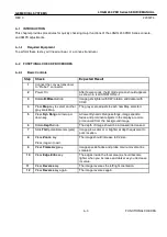
Basic Controls
Step
Check
Expected Result
1
Connect the convex transducer
to ”Probe 1” connector.
2
Power On
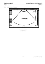
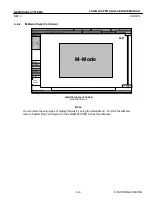
After few seconds, the B mode screen should appears
as shown in ILLUSTRATION 4–1.
3
Rotate B/M Gain knob
Image gets lighter with CW rotation and darker with
CCW.
4
Press Map key to select another
gray scale Map.
The gray scale adjusts to each new Map selected.
5
Press Dyn Range Arrow up or
down key.
At lower Dynamic Range settings, image speckle
fades and prominent objects in the display are more
pronounced from the background image.
6
Rotate Depth knob.
The depth of image should be increased /decreased.
7
Slide TGC potentiometers (pots)
Image grows darker or brighter at depth equivalent to
pot’s location.
8
Press Zoom. key.
Press it again to exit.
The image should increase to X2 size.
9
Press Frame Avg key.
Image speckle fades and probe or wire movement is
smeared.
10
Press Edge Enhc key.
The edges inside the focal area(s) should become
lighter when you increase and darker as you decrease
its value.
11
Press Reverse key.
The image reverses the left/right orientation.
12
Press Reverse key again.
The image reverses again.
Summary of Contents for LOGIQ 200
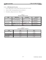
Page 4: ......
Page 8: ......
Page 10: ...05 23 00 MAC Page 2 of 2 ...
Page 28: ...05 23 00 MAC Page 2 of 2 ...
Page 87: ...LOGIQ α200 ...
Page 88: ...LOGIQ 200 PRO ...
Page 144: ......
Page 190: ......
Page 196: ......


