GE M
EDICAL
S
YSTEMS
D
IRECTION
2380207
, R
EVISION
7
LOGIQ™ 5 PRO S
ERVICE
M
ANUAL
Chapter 8 Replacement Procedures
8 - 89
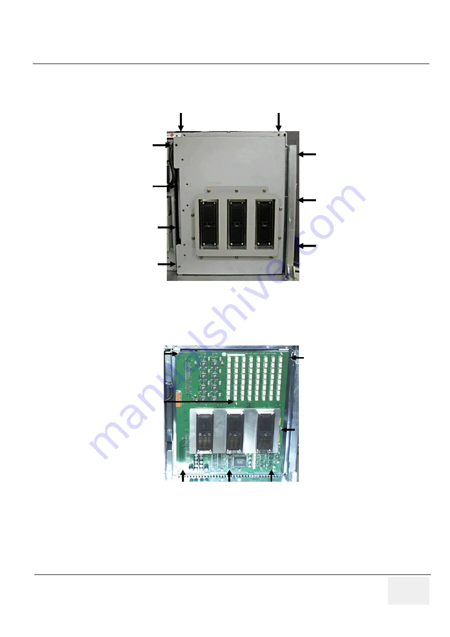
4.) Unscrew nine (7) screws (5-13) to open the RLY Board Cover. Refer to Figure 8-80.
NOTE:
Bind head screw is used at the location number (6).
5.) Unscrew seven (7) screws (14-20) to remove the RLY Board. Refer to Figure 8-81.
6.) Get the probe connector and pull the RLY board Out.
Figure 8-80 Removing the RLY board Cover
Figure 8-81 Unscrew 7 screws to remove the RLY Board
5
6
7
8
9
1 0
1 1
1 2
1 3
5
6
7
8
9
1 0
1 1
1 2
1 3
1 9
2 0
1 5
1 4
1 6
1 7
1 8
1 9
2 0
1 5
1 4
1 6
1 7
1 8
Summary of Contents for LOGIQ 5 PRO
Page 2: ...GE MEDICAL SYSTEMS DIRECTION 2407381 REVISION 7 LOGIQ 5 PRO SERVICE MANUAL Page 1 2 ...
Page 3: ......
Page 7: ...GE MEDICAL SYSTEMS DIRECTION 2380207 REVISION 7 LOGIQ 5 PRO SERVICE MANUAL ii iii ...
Page 462: ...GE MEDICAL SYSTEMS DIRECTION 2380207 REVISION 7 LOGIQ 5 PRO SERVICE MANUAL A 4 Index INDEX ...

