


GE
D
IRECTION
5573152-100, R
EV
. 2
LOGIQ E9 S
ERVICE
M
ANUAL
8 - 144
Section 8-6 - Replacing Top Console Parts
8-6-7-2
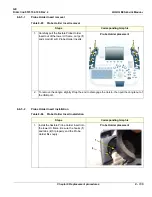
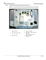
Upper OP Panel/Touch Panel Assembly installation
Table 8-96 Upper OP Panel/Touch Panel Assembly installation
Steps
Corresponding Graphic
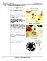
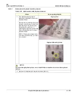
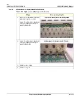
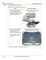
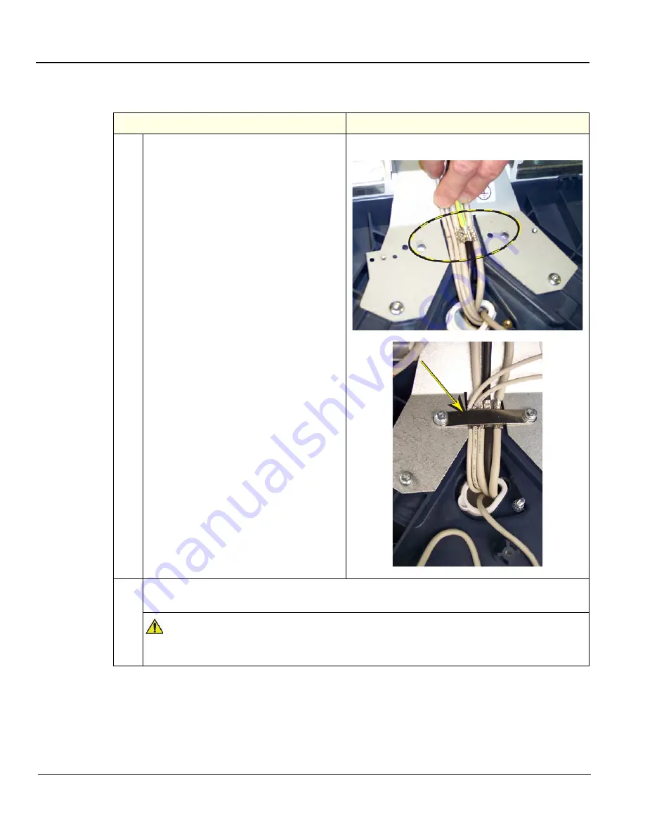
1.
Place the Upper OP Panel/Touch Panel
Assembly in the frame.
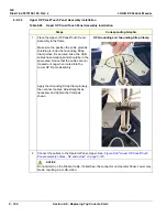
Make sure the position the cable grounds
shielding is under the Grounding Strap
Clamp when it is secured. Also, the USB
cables have markings and should be in the
same area. Notice that the cables are not
crossed or snug when routed into the
Lower OP Frame Assembly.
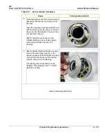
Apply the Grounding Strap Clamp loosely,
then connect cables. Adjust lengths as
necessary and tighten the Clamp as
shown.
OP Grounding and Grounding Strap Clamp
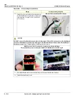
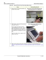
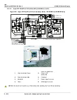
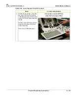
2.
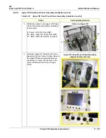
Connect the cables to the Operator Panel, Upper. See:
Figure 8-34 "Upper OP Panel/Touch
Panel assembly cables - R4 and earlier" on page 8-145
NOTICE
Do not stretch on the Ribbon Cable. If stretched, the connector on Operator Panel, Lower may
break, resulting in a malfunction.
Summary of Contents for LOGIQ E9
Page 2: ......
Page 11: ...GE DIRECTION 5573152 100 REV 2 LOGIQ E9 SERVICE MANUAL xi ZH CN KO ...
Page 753: ......
Page 754: ......


