background image

GE
D

IRECTION

 5573152-100, R

EV

. 2

LOGIQ E9 S

ERVICE

 M

ANUAL

9 - 116

Section 9-19 - Options

Section 9-19

Options

For Options Compatible configurations, See:

9-19-1 "Options Compatible Configurations" on page 9-120

.

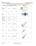
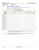
Table 9-59    Options 1 of 4 

ITEM

PART NAME

PART NUMBER

DESCRIPTION

QTY

FRU

1.

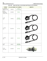
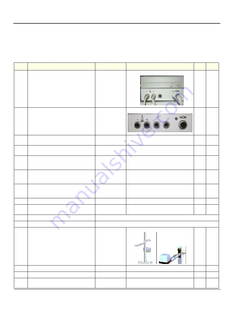
V Nav, Drive Bay 3D Tracking

System Electronics Unit

R3.x and earlier

5168286-20

1

Y

2.

Dr (System Electronics Unit)

R4.x and Later

5459862

1

Y

3.

V Nav, Drive Bay 3D Tracking System

Single 8mm Sensor Assembly

5168286-25

Replaced by 5168286-30

2

Y

4.

V Nav, Drive Bay 3D Tracking System

Dual 8mm Sensor Assembly

5168286-30

2

Y

5.

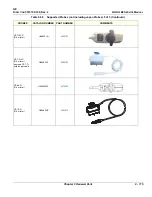
eTRAX Needle Sensor Spare Part

(Needle Tracking Option)

R2.0.5 or later

5408134 

6.

VirtuTRAX Sensor Spare Part

(Virtual Tracking Option)

R2.0.5 or later

5416625

7.

 V Nav, Drive Bay 3D Tracking System Mid 

Range Transmitter Assembly

for DriveBay 2 only

5457453

1

Y

8.

Drive Bay 2 Flat Transmitter

5437445

1

Y

9.

driveBAY 3D Tracking System Mid Range 

Transmitter

5168286-45

1

Y

10.

Cable, V Nav, Baybird Power

Cable Y, See: 

Table 9-57 - Peripherals Cables

11.

Cable, V Nav, USB BEP to BayBird

Cable Z, See: 

Table 9-57 - Peripherals Cables


12.

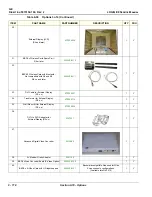
Stand for Tru3D Transmitter

5268740

1

Y

13.

V Nav Transmitter Stand Handles

5268740-30

1

Y

14.

V Nav Transmitter Stand Arm

5268740-10

1

Y

15.

V Nav Transmitter Stand Wheels

(set of 5)

5268740-20

1

Y

Summary of Contents for LOGIQ E9

Page 1: ...12 13 18 GEHC_FRNT_CVR FM LOGIQ E9 SERVICE MANUAL VERSION R6 Part Number 5573152 100 Revision Rev 2 ...

Page 2: ......

Page 3: ...T AU CLIENT QU IL INCOMBE DE LE FAIRE TRADUIRE NE PAS TENTER D INTERVENTION SUR LES ÉQUIPEMENTS TANT QUE LE MANUEL SERVICE N A PAS ÉTÉ CONSULTÉ ET COMPRIS LE NON RESPECT DE CET AVERTISSEMENT PEUT ENTRAÎNER CHEZ LE TECHNICIEN L OPÉRATEUR OU LE PATIENT DES BLESSURES DUES À DES DANGERS ÉLECTRIQUES MÉCANIQUES OU AUTRES DIESES KUNDENDIENST HANDBUCH EXISTIERT NUR IN ENGLISCHER SPRACHE FALLS EIN FREMDER ...

Page 4: ...O A CHOQUES ELÉTRICOS MECÂNICOS OU OUTROS ESTE MANUAL DE ASSISTÊNCIA ESTÁ DISPONÍVEL APENAS EM INGLÊS SE QUALQUER OUTRO SERVIÇO DE ASSISTÊNCIA TÉCNICA QUE NÃO A GEHC SOLICITAR ESTES MANUAIS NOUTRO IDIOMA É DA RESPONSABILIDADE DO CLIENTE FORNECER OS SERVIÇOS DE TRADUÇÃO NÃO TENTE EFECTUAR REPARAÇÕES NO EQUIPAMENTO SEM TER CONSULTADO E COMPREENDIDO PREVIAMENTE ESTE MANUAL A INOBSERVÂNCIA DESTE AVISO...

Page 5: ...ITTUMINEN SÄHKÖISKUN MEKAANISEN VIAN TAI MUUN VAARATILANTEEN VUOKSI ΤΟ ΠΑΡΟΝ ΕΓΧΕΙΡΙΔΙΟ ΣΕΡΒΙΣ ΔΙΑΤΙΘΕΤΑΙ ΣΤΑ ΑΓΓΛΙΚΑ ΜΟΝΟ ΕΑΝ ΤΟ ΑΤΟΜΟ ΠΑΡΟΧΗΣ ΣΕΡΒΙΣ ΕΝΟΣ ΠΕΛΑΤΗ ΑΠΑΙΤΕΙ ΤΟ ΠΑΡΟΝ ΕΓΧΕΙΡΙΔΙΟ ΣΕ ΓΛΩΣΣΑ ΕΚΤΟΣ ΤΩΝ ΑΓΓΛΙΚΩΝ ΑΠΟΤΕΛΕΙ ΕΥΘΥΝΗ ΤΟΥ ΠΕΛΑΤΗ ΝΑ ΠΑΡΕΧΕΙ ΥΠΗΡΕΣΙΕΣ ΜΕΤΑΦΡΑΣΗΣ ΜΗΝ ΕΠΙΧΕΙΡΗΣΕΤΕ ΤΗΝ ΕΚΤΕΛΕΣΗ ΕΡΓΑΣΙΩΝ ΣΕΡΒΙΣ ΣΤΟΝ ΕΞΟΠΛΙΣΜΟ ΕΚΤΟΣ ΕΑΝ ΕΧΕΤΕ ΣΥΜΒΟΥΛΕΥΤΕΙ ΚΑΙ ΕΧΕΤΕ ΚΑΤΑΝΟΗΣΕΙ ΤΟ ΠΑΡΟΝ Ε...

Page 6: ...E SLUŽEB OBSLUŽNÉHO PERSONÁLU NEBO PACIENTŮ VLIVEM ELEKTRICKÉHOP PROUDU RESPEKTIVE VLIVEM K RIZIKU MECHANICKÉHO POŠKOZENÍ NEBO JINÉMU RIZIKU DENNE SERVICEMANUAL FINDES KUN PÅ ENGELSK HVIS EN KUNDES TEKNIKER HAR BRUG FOR ET ANDET SPROG END ENGELSK ER DET KUNDENS ANSVAR AT SØRGE FOR OVERSÆTTELSE FORSØG IKKE AT SERVICERE UDSTYRET MEDMINDRE DENNE SERVICEMANUAL ER BLEVET LÆST OG FORSTÅET MANGLENDE OVER...

Page 7: ...ŽEISTAS DĖL ELEKTROS SMŪGIO MECHANINIŲ AR KITŲ PAVOJŲ DENNE SERVICEHÅNDBOKEN FINNES BARE PÅ ENGELSK HVIS KUNDENS SERVICELEVERANDØR TRENGER ET ANNET SPRÅK ER DET KUNDENS ANSVAR Å SØRGE FOR OVERSETTELSE IKKE FORSØK Å REPARERE UTSTYRET UTEN AT DENNE SERVICEHÅNDBOKEN ER LEST OG FORSTÅTT MANGLENDE HENSYN TIL DENNE ADVARSELEN KAN FØRE TIL AT SERVICELEVERANDØREN OPERATØREN ELLER PASIENTEN SKADES PÅ GRUNN...

Page 8: ...ИСТ ПО ТЕХОБСЛУЖИВАНИЮ ОПЕРАТОР ИЛИ ПАЦИЕНТ ПОЛУЧАТ УДАР ЗЛЕКТРИЧЕСКИМ ТОКОМ МЕХАНИЧЕСКУЮ ТРАВМУ ИЛИ ДРУГОЕ ПОВРЕЖДЕНИЕ ТОВА СЕРВИЗНО РЪКОВОДСТВО Е НАЛИЧНО САМО НА АНГЛИЙСКИ ЕЗИК АКО ДОСТАВЧИКЪТ НА СЕРВИЗНИ УСЛУГИ НА КЛИЕНТ СЕ НУЖДАЕ ОТ ЕЗИК РАЗЛИЧЕН ОТ АНГЛИЙСКИ ЗАДЪЛЖЕНИЕ НА КЛИЕНТА Е ДА ПРЕДОСТАВИ ПРЕВОДАЧЕСКА УСЛУГА НЕ СЕ ОПИТВАЙТЕ ДА ИЗВЪРШВАТЕ СЕРВИЗНО ОБСЛУЖВАНЕ НА ТОВА ОБОРУДВАНЕ ОСВЕН ВСЛ...

Page 9: ... STRUJNIM UDAROM MEHANIČKIM I DRUGIM OPASNOSTIMA TÁTO SERVISNÁ PRÍRUČKA JE K DISPOZÍCII LEN V ANGLIČTINE AK ZÁKAZNÍKOV POSKYTOVATEĽ SLUŽIEB VYŽADUJE INÝ JAZYK AKO ANGLIČTINU POSKYTNUTIE PREKLADATEĽSKÝCH SLUŽIEB JE ZODPOVEDNOSŤOU ZÁKAZNÍKA NEPOKÚŠAJTE SA VYKONÁVAŤ SERVIS ZARIADENIA SKÔR AKO SI NEPREČÍTATE SERVISNÚ PRÍRUČKU A NEPOROZUMIETE JEJ ZANEDBANIE TOHTO UPOZORNENIA MÔŽE VYÚSTIŤ DO ZRANENIA PO...

Page 10: ...ZCE DIŞINDAKİ BİR DİLDE OLMASINI İSTERSE KILAVUZU TERCÜME ETTİRMEK MÜŞTERİNİN SORUMLULUĞUNDADIR SERVİS KILAVUZUNU OKUYUP ANLAMADAN EKİPMANLARA MÜDAHALE ETMEYİNİZ BU UYARININ GÖZ ARDI EDİLMESİ ELEKTRİK ÇARPMASI YA DA MEKANİK VEYA DİĞER TÜRDEN KAZALAR SONUCUNDA TEKNİSYENİN OPERATÖRÜN YA DA HASTANIN YARALANMASINA YOL AÇABİLİR DİKKAT TR JA Traditional Chinese ...

Page 11: ...GE DIRECTION 5573152 100 REV 2 LOGIQ E9 SERVICE MANUAL xi ZH CN KO ...

Page 12: ... s electrical work on these products will comply with the requirements of the applicable electrical codes The purchaser of GE equipment shall only utilize qualified personnel i e GE s field engineers personnel of third party service companies with equivalent training or licensed electricians to perform electrical servicing on the equipment OMISSIONS ERRORS If there are any omissions errors or sugg...

Page 13: ...cated in any form in whole or in part without prior written permission of GE GE may revise this publication from time to time without written notice TRADEMARKS All products and their name brands are trademarks of their respective holders COPYRIGHTS All Material Copyright 2015 2018 by General Electric Company Inc All Rights Reserved ...

Page 14: ...hange Rev 1 2015 08 24 R6 Release Rev 2 2018 12 05 Update Pages Revision Pages Revision Pages Revision Title Page Rev 2 4 1 to 4 50 Rev 2 10 1 to 10 30 Rev 2 Warnings Rev 2 5 1 to 5 36 Rev 2 Back Cover N A TOC Rev 2 6 1 to 6 26 Rev 2 1 1 to 1 28 Rev 2 7 1 to 7 82 Rev 2 2 1 to 2 12 Rev 2 8 1 to 8 310 Rev 2 3 1 to 3 36 Rev 2 9 1 to 9 128 Rev 2 ...

Page 15: ... for the agreed upon time period This service manual provides installation and service information for the LOGIQ E9 ultrasound scanning unit It is divided in 10 chapters as shown below in Table 1 1 Contents in this service manual on page 1 2 Indications for Use The LOGIQ E9 is intended for use by a qualified physician for ultrasound evaluation Specific clinical applications and exam types include ...

Page 16: ...ecklist 4 Functional Checks Contains functional checks that must be performed as part of the installation or as required during servicing and periodic maintenance 5 Components and Functions Theory Contains block diagrams and functional explanations of the electronics 6 Service Adjustments Contains instructions on how to make any available adjustments to the LOGIQ E9 7 Diagnostics Troubleshooting P...

Page 17: ... Back End Boards Compatible Configurations on page 9 78 NOTE When not otherwise specified the contents of this manual applies to all LOGIQ E9 models Table 1 2 LOGIQ E9 Software Configurations and Hardware Software Compatibility Upgrade Options CONSOLE MODEL NUMBER DESCRIPTION SOFTWARE VERSION R6 6 Rev x x 5205000 LOGIQ E9 100 240 VAC N 5205000 2 LOGIQ E9 220 240 VAC N 5205000 3 LOGIQ E9 100 240 VA...

Page 18: ...cture of the LOGIQ E9 unit allows optimal usage of all scanning modes and probe types throughout the full spectrum of operating frequencies Signal flows from the Probe Connector Panel to the Front End and then over to the Back End Processor and finally to the monitor and peripherals System configuration is stored on the hard drive in the Back End Processor All necessary software is loaded from the...

Page 19: ...eled in one of three ways DANGER WARNING CAUTION When a hazard is present that can cause property damage but has absolutely no personal injury risk a NOTICE is used Notice Example Disk drive may crash NOTE Notes are used to provide important information about an item or a procedure NOTE Be sure to read the notes the information contained in a note can often save you time or effort DANGER DANGER IS...

Page 20: ...gle as seen throughout this chapter In addition to text several different graphical icons symbols may be used to make you aware of specific types of hazards that could possibly cause harm Even if a symbol isn t used in this manual it may be included for your reference Table 1 3 Standard hazard icons DANGER WARNING CAUTION BIOLOGICAL ELECTRICAL MOVING ACOUSTIC OUTPUT EXPLOSION SMOKE FIRE LASER HEAT...

Page 21: ...ther icons make you aware of specific procedures that should be followed Table 1 4 Standard hazard icons cont d RADIATION Table 1 5 Standard Icons that indicate that a special procedure is to be used AVOID STATIC ELECTRICITY TAG AND LOCK OUT WEAR EYE PROTECTION HAND PROTECTION FOOT PROTECTION Signed Date TAG LOCKOUT OR ...

Page 22: ...ype Class Label Used to indicate the degree of safety or protection United States only Prescription Requirement label Rear panel Authorized European Representative address Rear panel Equipment Type BF man in the box symbol IEC 878 02 03 indicates B Type equipment having a floating applied part Probe connectors including Doppler probe connector Equipment Type BF Applied Part man in the box with pad...

Page 23: ...d to alert the user to refer to the operator manual or other instructions when complete information cannot be provided on the label Rear Cover Rear of LCD Monitor Miscellaneous Probe Labels Symbol indicating that the Instructions for Use are supplied in electronic form Rear Panel Follow Instructions for Use ATTENTION Consult accompanying documents is intended to alert the user to refer to the oper...

Page 24: ... symbols to advise or warn the user Various Shear Wave Option Capacitor Pack Monitor Rear Cover ATTENTION Consult accompanying documents is intended to alert the user to refer to the operator manual or other instructions when complete information cannot be provided on the label General Warning Various Rear Cover Probe Label Warning Dangerous Voltage the lightning flash with arrowhead in equilatera...

Page 25: ...GE For disconnecting LOGIQ E9 from mains voltage after system shutdown please set the circuit breaker close to the mains inlet to OFF as described in 4 2 3 Power shut down on page 4 6 Operating Panel Protective Earth Indicates the protective earth grounding terminal Used several places inside the system Equipotential Indicates the terminal to be used for connecting equipotential conductors when in...

Page 26: ...onsole Rear of LCD Monitor inside or This product consists of devices that may contain mercury which must be recycled or disposed of in accordance with local state or country laws Within this system the backlight lamps in the monitor display contain mercury Rear Panel Rear of LCD Monitor inside ETL Listing Mark Monogram Rear Panel GOST Symbol Russia Regulatory Country Clearance Rear Panel EAC Symb...

Page 27: ...ill not result in any severe environmental pollution bodily injury or damage to any assets Probe Indicates the presence of hazardous substance s above the maximum concentration value Maximum concentration values for electronic information products as set by the People s Republic of China Electronic Industry Standard SJ T11364 2006 include the hazardous substances of lead mercury hexavalent chromiu...

Page 28: ...s Rear of the LCD monitor How to lower LCD prior to transport How to lock Operator Panel prior to transport DO NOT place a finger hand or any object on the joint of the monitor or monitor arm to avoid injury when moving the monitor and monitor arm Table 1 6 Product icons Continued 7 of 8 LABEL SYMBOL PURPOSE MEANING LOCATION CAUTION CAUTION ...

Page 29: ...ling instructions when servicing consoles that are used in a veterinary environment Non ionizing Electromagnetic Radiation Label Rear Panel Table 1 7 Product Labels on LOGIQ E9 consoles used in a veterinary environment LABEL LOCATION Side Covers Back Cover Probe s Table 1 6 Product icons Continued 8 of 8 LABEL SYMBOL PURPOSE MEANING LOCATION For Veterinary use only 5454608 5447716 ...

Page 30: ...LING TESTING AND ADJUSTING WARNING WARNING IF THE COVERS ARE REMOVED FROM AN OPERATING LOGIQ E9 SOME METAL SURFACES MAY BE WARM ENOUGH TO POSE A POTENTIAL HEAT HAZARD IF TOUCHED EVEN WHILE IN SHUTDOWN MODE WARNING WARNING BECAUSE OF THE LIMITED ACCESS TO CABINETS AND EQUIPMENT IN THE FIELD PLACING PEOPLE IN AWKWARD POSITIONS GE HAS LIMITED THE LIFTING WEIGHT FOR ONE PERSON IN THE FIELD TO 16 KG 35...

Page 31: ...s turned off when the cord is still plugged into the AC Outlet WARNING WARNING Risk of electrical shock system must be turned off and disconnected from power source Cord must be controlled at all times Wait for at least 20 seconds for capacitors to discharge as there are no test points to verify isolation The Amber light on the Op Panel On Off button will turn off Beware that the Main Power Supply...

Page 32: ...DLING AND PROTECT FROM DAMAGE WHEN NOT IN USE DO NOT USE A DAMAGED OR DEFECTIVE PROBE FAILURE TO FOLLOW THESE PRECAUTIONS CAN RESULT IN SERIOUS INJURY AND EQUIPMENT DAMAGE WARNING WARNING REMEMBER If the front caster swivel lock is engaged for transportation pressing the release pedal once disengages the swivel lock You must depress the release pedal a second time to engage the brake WARNING WARNI...

Page 33: ...ROLLED MOTION AND COSTLY DAMAGE ALWAYS BE SURE THE PATHWAY IS CLEAR USE SLOW CAREFUL MOTIONS USE TWO PEOPLE WHEN MOVING ON INCLINES OR LIFTING MORE THAN 16 KG 35 LBS CAUTION TO AVOID INJURY OR DAMAGE TO THE MONITOR MAKE SURE THERE IS NOTHING WITHIN RANGE OF THE LCD BEFORE MOVING THE MONITOR AND MONITOR ARM THIS INCLUDES PEOPLE AS WELL AS THINGS CAUTION Ensure that nobody touches the console arm fr...

Page 34: ...fore connecting a probe to the scanner Inspect the probe prior to each use for damage or degradation to the housing cable strain relief lens seal connector pins locking mechanism Do not use a damaged or defective probe Never immerse the probe connector or adapter into any liquid The system has more than one type of probe port Use the appropriate probe port designed for the probe you are connecting...

Page 35: ...TESTING AND ADJUSTING WARNING WARNING IF THE COVERS ARE REMOVED FROM AN OPERATING LOGIQ E9 SOME METAL SURFACES MAY BE WARM ENOUGH TO POSE A POTENTIAL HEAT HAZARD IF TOUCHED EVEN WHILE IN SHUT DOWN MODE WARNING WARNING EXPLOSION WARNING DO NOT OPERATE THE EQUIPMENT IN AN EXPLOSIVE ATMOSPHERE OPERATION OF ANY ELECTRICAL EQUIPMENT IN SUCH AN ENVIRONMENT CONSTITUTES A DEFINITE SAFETY HAZARD WARNING WA...

Page 36: ...GIQ E9 When servicing parts of the system where there is exposure to voltage greater than 30 Volts 1 Turn off the scanner 2 Unplug the system 3 Maintain control of the system power plug 4 Wait for at least 20 seconds for capacitors to discharge as there are no test points to verify isolation The Amber light on the Op Panel On Off button will turn off 5 DISCONNECT THE EPS EXTENDED POWER SHUTDOWN BA...

Page 37: ...regulation is to protect employees in the transportation industry as well as the people who will receive or open this package NOTE The US Department of Transportation DOT has ruled that items that were saturated and or dripping with human blood that are now caked with dried blood or which were used or intended for use in patient care are regulated medical waste for transportation purposes and must...

Page 38: ...mmunity from electrostatic discharge radiated and conducted RF fields magnetic fields and power line transient requirements Applicable standards are 47CFR Part 18 IEC60601 1 2 2001 NOTE For CE Compliance it is critical that all covers screws shielding gaskets mesh clamps are in good condition installed tightly without skew or stress Proper installation following all comments noted in this service ...

Page 39: ...tributor or appropriate support resource as listed below Before you call identify the following information and acquire image Alt D to send to the Customer Care team 1 System ID serial number 2 Software version 3 Date and time of occurrence 4 Sequence of events leading to issue 5 Is the issue repeatable 6 Imaging mode probe preset application 7 Media brand speed capacity type 8 Save secondary imag...

Page 40: ... Latin America Service Application Support 1 262 524 5300 1 262 524 5698 Europe GE Ultraschall Deutschland GmbH Beethovenstrasse 239 Postfach 11 05 60 D 42655 Solingen Germany Support Phone 49 0 212 2802 652 Support Fax 49 0 2122 8024 31 EAGM Egypt Service Center UAE Service Center 0020 2322 1252 00971 8003646 Asia Singapore GE Ultrasound Asia Service Department Ultrasound 298 Tiong Bahru Road 15 ...

Page 41: ...edical Systems Ultrasound and Primary Care Diagnostics LLC 9900 Innovation Drive Wauwatosa WI 53226 USA 414 721 3865 Table 1 11 Authorized Representative AUTHORIZED REPRESENTATIVE The location of the CE marking is shown in the Safety chapter of this manual Authorized EU Representative European registered place of business GE Medical Systems SCS 283 rue de la Minière 78530 BUC France ...

Page 42: ...GE DIRECTION 5573152 100 REV 2 LOGIQ E9 SERVICE MANUAL 1 28 Section 1 10 Customer assistance This page was intentionally left blank ...

Page 43: ... 2 1 Chapter 2 Site preparations Section 2 1 Overview 2 1 1 Purpose of this chapter This chapter provides the information required to plan and prepare for the setup of a LOGIQ E9 Included are descriptions of the facility and electrical needs to be met by the purchaser of the LOGIQ E9 ...

Page 44: ... cooling system 2 2 1 4 Lighting Bright light is needed for LOGIQ E9 installation updates and repairs However operator and patient comfort may be optimized if the room light is subdued and indirect Therefore a combination lighting system dim bright is recommended Keep in mind that lighting controls and dimmers can be a source of EMI which could degrade image quality These controls should be select...

Page 45: ...lines not shared with any other circuit and a full size ground wire from the distribution panel to the LOGIQ E9 outlet NOTE Please note that image artifacts can occur if at any time within the facility the ground from the main facility s incoming power source to the Ultrasound unit is only a conduit 2 2 2 2 Electrical requirements for LOGIQ E9 In the table below the electrical specifications for L...

Page 46: ...ent local state and national electrical codes 2 2 2 6 LOGIQ E9 power plug If the LOGIQ E9 arrives without a power plug or with the wrong plug you must contact your GE dealer or the installation engineer must supply what is locally required 2 2 2 7 Power stability requirements Voltage drop out Max 10 ms Power transients all applications Less than 25 of nominal peak voltage for less than 1 milliseco...

Page 47: ...likely reason a LOGIQ E9 will have noisy images Check grounding of the power cord and power outlet Replace all screws RF gaskets covers cores After you finish repairing or updating the LOGIQ E9 replace all covers and tighten all screws Any cable with an external connection requires a magnet wrap at each end Install the Card Rack cover over the Card Rack Loose or missing covers or RF gaskets allow ...

Page 48: ... C 14 to 140 ºF 10 to 60 C 14 to 140 ºF 10o to 50 o C 14 to 122 ºF Temperatures in degrees Celsius o C conversion to degrees F o F o C 9 5 32 NOTICE SYSTEMS AND ELECTRONIC PROBES ARE DESIGNED FOR STORAGE TEMPERATURES OF 10 TO 50 degrees C or 60 degrees C DEPENDING ON THE TYPE OF PROBE WHEN EXPOSED TO LARGE TEMPERATURE VARIATIONS THE PRODUCT SHOULD BE KEPT IN ROOM TEMPERATURE FOR 10 HOURS BEFORE US...

Page 49: ... qualified personnel The products involved and the accompanying electrical installations are highly sophisticated and special engineering competence is required All electrical work on these products must comply with the requirements of applicable electrical codes The purchaser of GE equipment must only utilize qualified personnel to perform electrical servicing on the equipment The desire to use a...

Page 50: ...cated line shall consist of one phase two lines not shared with any other circuit and a full size ground wire from the distribution panel to the Ultrasound outlet Dedicated single branch power outlet of adequate amperage see Table 2 3 Electrical specifications for the LOGIQ E9 on page 2 3 meeting all local and national codes which is located less than 2 5 m 8 ft from the LOGIQ E9 s proposed locati...

Page 51: ...ctors Desk 2 File Cabinet 3 Film Viewer 4 Counter Top 5 Counter Top and Sink with hot and cold water 6 Overhead Lights Dimmer Dual Level Lighting bright and dim 7 Emergency Oxygen 8 Suction Line 9 LOGIQ E9 10 Dedicated Power Outlet Circuit Breaker protected and easily accessible 11 Network Interface 12 457 mm 18 inches distance of LOGIQ E9 from wall or objects 13 Stool 14 Footswitch 15 Storage for...

Page 52: ...cold water and Supplies Storage 4 Linen Supply 5 Probes Supplies 6 Examination Table 1930 x 610 mm 76 x 24 inches 7 Footswitch 8 Stool 9 LOGIQ E9 10 External Peripherals 11 Dedicated Power Outlet Circuit Breaker protected and easily accessible 12 Network Interface 13 457 mm 18 inches distance of LOGIQ E9 from wall or objects 14 GE Cabinet for Software and Manuals 4 1 3 11 6 13 1 2 1 2 Auto Auto B ...

Page 53: ...canning continues With DICOM images can be archived stored and retrieved faster easier and at a lower cost 2 3 5 5 DICOM option setup requirements To configure the LOGIQ E9 to work with other network connections the site s network administrator must provide information to complete the form in Figure 2 3 Worksheet for DICOM Network Information on page 2 12 Ensure that there are no spaces in any fie...

Page 54: ...tore 3 Store 1 MAKE IP PORT AE TITLE DICOM Print Storage Commit DICOM MPPS Worklist Network Speed Associated Storage AE _____________ __Raw Data __Allow Multiframe __Structured Reporting Compression_______ __Raw Data __Allow Multiframe __Structured Reporting Compression_______ __Raw Data __Allow Multiframe __Structured Reporting Compression_______ Vendor ___________ Print Size _________ Medium ___...

Page 55: ...r This chapter contains information needed to set up the LOGIQ E9 Included is a procedure that describes how to receive and unpack the equipment and how to file a damage or loss claim How to prepare the facility and unit of the actual setup and how to check and test the unit probes and external peripherals for electrical safety are included in this procedure ...

Page 56: ...TION 2 HOURS OR MORE DEPENDENT ON THE CONFIGURATION INSTALL INSITE ILINK 0 5 HOUR DANGER WHEN USING ANY TEST INSTRUMENT THAT IS CAPABLE OF OPENING THE AC GROUND LINE I E METER S GROUND SWITCH IS OPEN DON T TOUCH THE UNIT CAUTION TO PREVENT ELECTRICAL SHOCK CONNECT THE UNIT TO A PROPERLY GROUNDED POWER OUTLET DO NOT USE A THREE TO TWO PRONG ADAPTER THIS DEFEATS SAFETY GROUNDING CAUTION DO NOT WEAR ...

Page 57: ... THE USER MANUAL S SHOULD BE FULLY READ AND UNDERSTOOD BEFORE OPERATING THE LOGIQ E9 AND KEPT NEAR THE UNIT FOR QUICK REFERENCE CAUTION ACOUSTIC OUTPUT HAZARD ALTHOUGH THE ULTRASOUND ENERGY TRANSMITTED FROM THE LOGIQ E9 PROBE IS WITHIN AIUM NEMA STANDARDS AVOID UNNECESSARY EXPOSURE ULTRASOUND ENERGY CAN PRODUCE HEAT AND MECHANICAL DAMAGE ...

Page 58: ...3 3 2 Receiving and unpacking warnings CAUTION TWO PEOPLE ARE NEEDED TO UNPACK THE UNIT BECAUSE OF ITS WEIGHT ATTEMPTS TO MOVE THE UNIT CONSIDERABLE DISTANCES OR ON AN INCLINE BY ONE PERSON COULD RESULT IN INJURY OR DAMAGE OR BOTH TWO PEOPLE ARE REQUIRED WHENEVER A PART WEIGHING 16 KG 35 LBS OR MORE MUST BE LIFTED CAUTION REMEMBER TO USE RELEVANT PERSONAL PROTECTING EQUIPMENT PPE DURING PACKING UN...

Page 59: ...age is apparent Table 3 2 Damage in transportation STEP TASK 1 Write Damage In Shipment on ALL copies of the freight or express bill BEFORE delivery is accepted or signed for by a GE representative or hospital receiving agent 2 Report the damage to the carrier Whether noted or concealed damage MUST be reported to the carrier immediately upon discovery or in any event within 14 days after receipt a...

Page 60: ...tion has been improper a Tilt or TIPNTELL indicator and a Shock indicator have been attached to the transportation box 3 3 4 2 Position of the Tilt or TipNTell and Shock indicators The Tilt and Shock indicators have been attached to the side of the transportation box NOTE Before cutting the straps check the Tilt or TIPNTELL and Shock indicators to make sure they have not been triggered If triggere...

Page 61: ...OGIQ E9 Transportation Box Label is located on the transportation box Figure 3 3 LOGIQ E9 Transportation Box Labeling SYMBOL DEFINITION COMMENTS SYMBOL DEFINITION COMMENTS RECYCLING Recyclable Wood or RECYCLING China Specific KEEP DRY protect from moisture FRAGILE Handle with Care TOP UPRIGHT Transportation and Storage DO NOT STACK ...

Page 62: ...ing the LOGIQ E9 ultrasound scanning unit Images are ONLY for reference wear proper PPE when handling packaging gloves safety shoes etc Table 3 3 Uncrating Instructions Steps Corresponding Graphic 1 Before cutting the straps check Shock and Tilt Tags to make sure they have not been triggered If damaged report it to the carrier If not then cut the straps around the crate 2 Remove the top cover 1 2 ...

Page 63: ...Q E9 SERVICE MANUAL Chapter 3 LOGIQ E9 Setup 3 9 3 Remove the outside shipping box Note Two people are recommended for performing this step 4 Remove the LCD foam Table 3 3 Uncrating Instructions Continued Steps Corresponding Graphic 3 4 ...

Page 64: ...ng the equipment 5 Remove the a Probes and b accessory boxes 6 Remove the L shaped Cardboard divider Note Use special care when removing the divider 7 Remove the OP panel foam placed between the monitor and probe holders Table 3 3 Uncrating Instructions Continued Steps Corresponding Graphic 6 7 ...

Page 65: ...and back Remove the wooden ramp 9 Attach the wooden ramp to the Pallet Base with Velcro on the rear side of the LOGIQ E9 10 Loosen the tie down strap at the front of the LOGIQ E9 Push the brass piece to pull back handle then push brass piece to loosen strap 11 Disconnect the tie down strap at the rear of the LOGIQ E9 Table 3 3 Uncrating Instructions Continued Steps Corresponding Graphic 8 ...

Page 66: ...ow Density Polyethylene Section 3 5 Preparing for setup 3 5 1 Verify Customer Order Compare items received by the customer to that which is listed on the delivery order Report any items that are missing back ordered or damaged 12 Pull the LOGIQ E9 down the Pallet Base ramp Note Remember to pull in the LOGIQ E9 from the back for safer transportation 13 Remove the clear plastic wrapped around the LO...

Page 67: ...ransportation on page 3 3 3 3 Damage in transportation on page 3 5 in the beginning of this manual 3 5 2 1 LOGIQ E9 voltage settings See 3 6 3 1 Verification of the LOGIQ E9 s voltage setting on page 3 19 3 5 3 Volume Navigation Stand To assemble the Volume Navigation Stand See 8 12 2 Assembling or replacing the Roll Stand on page 8 293 or 8 12 4 On Board V Nav Stand Option Contents location and p...

Page 68: ...er Label and ETL testing laboratories safety rating label ETL may not be present For location of Rating Plate Label see Figure 3 12 Rating Plate s Location How to Identify Console Model Number on page 3 16 Figure 3 4 Back Cover Label with ETL Label Figure 3 5 Rating Plate Label R3 x and earlier 100 120V shown ...

Page 69: ...d Figure 3 6 Rating Plate Label R4 x x Figure 3 7 Rating Plate Label R5 x x Figure 3 8 Rating Plate Label R6 x x 7 5205000 8 XXXXXXXXX Month YYYY 5205000 9 01 01122222333334 11 YYMMDD 21 XXXXXXUS6 XXXXXXUS6 YYYY MM DD LOGIQ E9 REF UDI S N GE Medical Systems Ultrasound and Primary Care Diagnostics LLC 9900 Innovation Drive Wauwatosa WI USA 53226 100 120V 10 Amps 220 240V 8 Amps 50 60 Hz ...

Page 70: ... to XDclear 2 0 Figure 3 10 Rating Plate Label R4 upgraded to XDclear 2 0 Figure 3 11 Rating Plate Label R5 upgraded to XDclear 2 0 Figure 3 12 Rating Plate s Location How to Identify Console Model Number 01 01122222333334 21 XXXXXXUS6 LOGIQ E9 R3 to XDclear 2 0 UPG UDI 5589819 REF 01 01122222333334 21 XXXXXXUS6 LOGIQ E9 R4 to XDclear 2 0 UPG UDI 5589818 REF 01 01122222333334 21 XXXXXXUS6 LOGIQ E9...

Page 71: ...ro Magnetic Interference EMI Many of the covers shields and screws are provided primarily to protect the LOGIQ E9 from image artifacts caused by this interference For this reason it is imperative that all covers and hardware are installed and secured before the unit is put into operation See 2 2 3 EMI limitations on page 2 5 for more information about EMI protection ...

Page 72: ...it are summarized in Table 3 4 Dimensions given with floating keyboard stowed for transport and the LCD Monitor down 3 6 2 3 Weight with monitor and peripherals 3 6 2 4 Acoustic noise output Less than 48 dB A at 20 degrees Celsius measured in the operators head position 20 cm in front of the keyboard s right corner at 1 30 m above the floor and in a distance of 1 meter at all four sides 1 meter ab...

Page 73: ...on the I O Rear Panel NOTE Accessory equipment connected to the analog and digital interfaces must be certified according to the respective IEC standards e g IEC60950 for data processing equipment and IEC60601 1 for medical equipment Furthermore all complete configurations shall comply with the valid version of the system standard IEC60601 1 1 Everybody who connects additional equipment to the sig...

Page 74: ...isplay In the event that a display connected to DVI I video output is not capable of displaying the resolution being used by the main display then the auxiliary display will be blank or show a no signal message The DVI D Video output deliver a minimum of 1280x1024 60Hz 24 bit color depth 3 6 4 2 Connect USB Flash Drive Refer to the current revision of the LOGIQ E9 Basic User Manual Chapter 3 Secti...

Page 75: ...Refer to Chapter 10 in the Basic User Manual for more information 3 6 6 Connecting Probes 3 6 6 1 Introduction to Connecting Probes Probes can be connected at any time whether the unit is on or off R4 x and later LOGIQ E9s have one type of probe ports four DLP probe ports Figure 3 14 Figure 3 14 Probe connectors four DLP Probe Ports R4 x and Later ...

Page 76: ...ndle clockwise to the full vertical position to lock in place 6 Position the probe cable so that it is not resting on the floor 3 6 6 3 Disconnect a probe 1 Select a different probe or Freeze the image before removing a probe in order to avoid disconnecting a live probe 2 Rotate the lock handle counter clockwise to the horizontal position to unlock the connector 3 Remove the connector from the por...

Page 77: ...Power ON Boot Up on page 4 3 DANGER ALWAYS CONNECT THE UNIT TO A FIXED POWER SOCKET WHICH HAS THE PROTECTIVE GROUNDING CONNECTOR DANGER NEVER USE A THREE TO TWO PRONG ADAPTER THIS DEFEATS THE SAFETY GROUND DANGER ENSURE THAT THE POWER CORD AND PLUG ARE INTACT AND THAT THE POWER PLUG IS THE PROPER HOSPITAL GRADE TYPE WHERE REQUIRED CAUTION LOGIQ E9 REQUIRES ALL COVERS OPERATE THIS UNIT ONLY WHEN AL...

Page 78: ...urned off 2 Uncoil the power cable allowing sufficient slack so that the unit can be moved slightly 3 Verify that the power cable is without any visible scratches or any sign of damage 4 Verify that the on site mains voltage is within the limits indicated on the rating label near the Circuit Breaker on the rear of the unit 5 Connect the Power Cable s female plug to the Power Inlet at the rear of t...

Page 79: ...n after a few seconds listen to the fan sound b Power is distributed to the peripherals Operator Panel Console Monitor Front End Processor and Back End Processor c Back End Processor and rest of the LOGIQ E9 starts with the sequence listed in the next steps d Back End Processor is turned ON and starts to load the software e The Start Screen is displayed on the monitor f A start up bar indicating t...

Page 80: ... 3 6 Completing the setup 3 6 7 4 Switch ON the AC Power to LOGIQ E9 cont d NOTE Total time used for start up is typically less than 170 seconds If starting after a power loss or a lock up the start up time may be up to four minutes Figure 3 17 2D Screen on the display ...

Page 81: ...r The system remains ON and ready for a new user to log on If the Logoff button is dimmed it indicates that no user is logged on to the unit at the moment Shutdown Use this button to shut down the system The entire system will shut down It is recommended to perform a full shutdown at least once a week If the Shutdown button is dimmed press the ON OFF button or Alt F10 to shut down the unit Cancel ...

Page 82: ...y for a new user to log on If the Logoff button is dimmed it indicates that no user is logged on to the unit at the moment Shutdown Use this button to shut down the system The entire system will shut down It is recommended to perform a full shutdown at least once a week If the Shutdown button is dimmed press the ON OFF button or Alt F10 to shut down the unit Cancel Use this button to exit from the...

Page 83: ... 100 REV 2 LOGIQ E9 SERVICE MANUAL Chapter 3 LOGIQ E9 Setup 3 29 3 6 9 Complete power down 1 Press once on the ON OFF button on the Operator Panel to display the System Exit menu Figure 3 20 Press once on the ON OFF button ...

Page 84: ... on the Operator Panel indicating that you can continue with the next step 3 Switch off the Mains Power Circuit Breaker located on the rear of the unit This will cut power distribution within the unit Before returning a system to the customer perform the functional checks See Section 4 3 Functional checks on page 4 26 Figure 3 21 System Exit Download menu NOTICE Be sure to wait with the next step ...

Page 85: ...ngs on page 4 20 Set Dataflow see 4 2 11 6 Connectivity Recording Dataflow settings on page 4 19 Set Buttons see 4 2 11 7 Connectivity Recording the Print Key Assignments on page 4 20 Set up System Admin see 4 2 11 9 Admin Recording the Software Option Keys on page 4 22 Set up Users see 4 2 11 10 Admin Users on page 4 23 Set up Backup management see 4 2 11 11 System Data Store Management on page 4...

Page 86: ...Refer to the current revision of the LOGIQ E9 Options Manual Direction 5180409 100 WLAN Wireless LAN R4 x x and later Refer to the current revision of the LOGIQ E9 Options Manual Direction 5335640 100 WLAN V3 Wireless LAN R6 x x and later Refer to the current revision of the LOGIQ E9 Options Manual Direction 5694231 100 Patient I O ECG Option R2 x x or later Refer to the current revision of the LO...

Page 87: ...This password is specific for each LOGIQ E9 Table 3 6 Peripheral Checks Step Task to do Notes 1 Press Freeze Stops image acquisition 2 Press Print 1 Print 2 Print 3 or Print 4 on the Control Panel Prints image displayed on the screen on Black and White or Color printer depending on the key assignment configuration 3 Press VIDEO icon on the Control Panel Brings up the DVR Touch Panel if the custome...

Page 88: ...n be imported from the media 5 Press Save to save the new setting 6 Restart to save and activate the settings and adjustments you have done so far CAUTION INCORRECT PASSWORD ENTRY WILL RESULT IN LOSS OF SYSTEM OPTIONS IF PASSWORD IS INCORRECT PLEASE CONTACT YOUR LOCAL GE SERVICE REPRESENTATIVE OR THE ONLINE CENTER Figure 3 22 Option Keys File in R5 and later Import Option keys file can be imported...

Page 89: ...able You will only need a Crossover Cable for network use to connect the two units this way 1 Connect one end of the crossed network cable to the network connector on the LOGIQ E9 2 Connect the other end to the network connector to the Workstation see the Workstation Service Manual 3 8 1 3 2 Connection via a Peer to Peer Network You will need a network switch and one network cable for each unit co...

Page 90: ...le INSTALLATION SHIPMENT L A I R E S V E R L E D O M A D F N O I T P I R C S E D ZIP CODE DESTINATION NAME AND ADDRESS 46 303268P1 Rev 14 L A I R E S V E R L E D O M A D F N O I T P I R C S E D OCP BS ORD R Y A D O M E T A D M O O R T C I R T S I D ZIP CODE DESTINATION NAME AND ADDRESS CUSTOMER NO SYSTEM LTD EMPLOYEE NO g g Mailing Address GIB European Central Admin Product Locator Cards VÀKUUMTEC...

Page 91: ...checking major functions of the LOGIQ E9 scanner and diagnostics instructions using the built in service software 4 1 2 Special Equipment required An empty blank DVD R disk At least one probe ideally you should check all the site probes used by the system For available probes see Section 9 18 Probes on page 9 111 ECG Harness CABLE ECG MARQ AHA AMERICA P N 164L0025 LEADWIRES ECG MARQ AHA AMERICA P ...

Page 92: ...nergy Control and Power Lockout for LOGIQ E9 WHEN SERVICING PARTS OF THE SYSTEM WHERE THERE IS EXPOSURE TO VOLTAGE GREATER THAN 30 VOLTS 1 TURN OFF THE SCANNER 2 UNPLUG THE SYSTEM 3 MAINTAIN CONTROL OF THE SYSTEM POWER PLUG 4 WAIT FOR AT LEAST 20 SECONDS FOR CAPACITORS TO DISCHARGE AS THERE ARE NO TEST POINTS TO VERIFY ISOLATION THE AMBER LIGHT ON THE OP PANEL ON OFF BUTTON WILL TURN OFF 5 DISCONN...

Page 93: ...WER SOCKET WHICH HAS THE PROTECTIVE GROUNDING CONNECTOR DANGER NEVER USE A THREE TO TWO PRONG ADAPTER THIS DEFEATS THE SAFETY GROUND DANGER ENSURE THAT THE POWER CORD AND PLUG ARE INTACT AND THAT THE POWER PLUG IS THE PROPER HOSPITAL GRADE TYPE WHERE REQUIRED CAUTION SYSTEM REQUIRES ALL COVERS OPERATE THIS UNIT ONLY WHEN ALL BOARD COVERS AND FRAME PANELS ARE SECURELY IN PLACE THE COVERS ARE REQUIR...

Page 94: ...Uncoil the power cable allowing sufficient slack so that the unit can be moved slightly 3 Verify that the power cable is without any visible scratches or any sign of damage 4 Verify that the on site mains voltage is within the limits indicated on the rating label near the Circuit Breaker on the rear of the unit 5 Connect the Power Cable s female plug to the Power Inlet at the rear of the unit 6 Lo...

Page 95: ... End Processor and Back End Processor c Back End Processor and rest of scanner starts with the sequence listed in the next steps d Back End Processor is turned ON and starts to load the software e The Start Screen is displayed on the monitor f A start up bar indicating the time used for software loading is displayed on the monitor g The software initiates and sets up the Front End electronics and ...

Page 96: ...button to log off the current user The system remains ON and ready for a new user to log on If the Logoff button is dimmed it indicates that no user is logged on to the unit at the moment Shutdown Use this button to shut down the system The entire system will shut down It is recommended to perform a full shutdown at least once a week If the Shutdown button is dimmed to shut down the unit Cancel Us...

Page 97: ...activity and print the message Please wait Shutdown in progress in the LCD display on the Operator Panel Next it starts to shut down itself The time to shutdown the LOGIQ E9 including the Back End Processor may vary from 10 seconds up to approximately 1 minute The last thing that shuts down is the light on the Operator Panel indicating that you can continue with the next step NOTE Sleep Mode only ...

Page 98: ...he Lock and brake release button s Figure 4 3 button 1 and pull the Top Console out of the locked position until the Top console is in the desired position 2 Release the button s 4 2 4 2 To lock the Top Console 1 Press and hold down the Lock and brake release button s Figure 4 3 button 1 while pushing the Top Console in the locked position 2 Release the button s 4 2 4 3 To move the floating Top Co...

Page 99: ... and left right horizontally NOTE The LCD Monitor can move approximately 100 mm 3 94 inches vertically and 250 mm 9 84 inches horizontally Figure 4 4 LCD Monitor Position and Lock 1 Unlocked LCD Monitor 2 Locked LCD Monitor Figure 4 5 LCD Monitor Positions Daeil Arm 1 Tilt LCD Monitor 3 Move Monitor Up and Down 2 Move Monitor Back and Forth 4 Monitor front view Monitor tilted down side view 1 2 4 ...

Page 100: ...ight horizontally NOTE The LCD Monitor can move approximately 100 mm 3 94 inches vertically and 250 mm 9 84 inches horizontally Figure 4 6 LCD Monitor Positions Ergotron Arm 1 Vertical Travel 150mm 4 Pan Arm Rotation 45º 90º total 2 Rotation at Mount 90º 180º total 5 LCD Translation 350mm 3 Lift Arm Rotation 135º 270º total 6 Tilt a No Collistion b Approximately 20º based on Pan Arm Off set c 85º ...

Page 101: ...ckwise to unlock the LCD Monitor The LCD Monitor can be moved freely in all directions 4 2 5 2 To lock the LCD Monitor Turn the knob clockwise to raise the lock and move the LCD Monitor into the parked position 4 2 5 3 LCD Monitor position for Transport Lock Arm and tilt LCD Monitor down Figure 4 7 LCD Monitor transport Position Daeil Arm shown ...

Page 102: ... See Table 1 8 Basic User Manual and Release Notes per LOGIQ E9 console on page 1 20 4 2 8 Space Management Refer to the appropriate version of the LOGIQ E9 Basic User Manual Chapter 16 or the appropriate LOGIQ E9 Release Notes See Table 1 8 Basic User Manual and Release Notes per LOGIQ E9 console on page 1 20 to perform the following tasks Configuring the Disk Management Function Setting the Disk...

Page 103: ...ivel lock 4 2 10 2 To prepare the LOGIQ E9 to be moved 1 If not locked move the keyboard console and LCD monitor to the park position see 4 2 4 Top Console position adjustment on page 4 8 and 4 2 5 LCD Monitor Positions and Lock on page 4 9 2 Turn the system off including the circuit breaker see 4 2 3 Power shut down on page 4 6 and remove the plug from the wall 3 Disconnect all cables linking the...

Page 104: ...d console and LCD monitor to the park position see 4 2 4 Top Console position adjustment on page 4 8 and 4 2 5 LCD Monitor Positions and Lock on page 4 9 2 Disconnect all probes and secure them in their boxes 3 Ensure that the transporting vehicle is appropriate for the unit s weight 4 Park the vehicle on a level surface for loading and unloading 5 Secure the unit while it is on the lift to preven...

Page 105: ...ded here for convenience but content will be included if selected during Backup process Utility Connectivity 4 2 11 5 Connectivity Recording Device Destination settings on page 4 18Service see 4 2 11 5 Connectivity Recording Device Destination settings on page 4 18 Dataflow see 4 2 11 6 Connectivity Recording Dataflow settings on page 4 19 Buttons see 4 2 11 7 Connectivity Recording the Print Key ...

Page 106: ...From the Touch Panel select Utility Connectivity WLAN 2 Record all settings in Table 4 3 Record settings from WLAN screen on page 4 16 Table 4 2 Record settings from TCP IP screen PARAMETER VALUE COMPUTER NAME IP SETTINGS IP ADDRESS SUBNET MASK DEFAULT GATEWAY NETWORK SPEED Table 4 3 Record settings from WLAN screen PARAMETER VALUE NETWORK NAME SSID NETWORK AUTHENTICATION DATA ENCRYPTION NETWORK K...

Page 107: ... settings in Table 4 4 Record settings for My Computer from Device screen on page 4 17 4 Record all settings in Table 4 5 Record settings for each device listed in Device table on page 4 17 Figure 4 9 Device settings Table 4 4 Record settings for My Computer from Device screen PARAMETER VALUE AE TITLE PORT NO MAC ADDRESS NOTE This information may be located in the TCP IP page in some versions of s...

Page 108: ...ng Device Destination settings 1 From the Touch Panel select Utility Connectivity Service 2 Record all settings in Table 4 6 Record settings from Service screen on page 4 18 for each Destination Device and Service Figure 4 10 Service settings Table 4 6 Record settings from Service screen DESTINATION DEVICE PROPERTIES ...

Page 109: ...ataflow settings 1 From the Touch Panel select Utility Connectivity Dataflow 2 Record all settings in Table 4 7 Record settings from Service screen on page 4 19 Figure 4 11 Dataflow settings Table 4 7 Record settings from Service screen DESTINATION DEVICE NAME SERVICES TYPES FOR EACH DESTINATION DEVICE PROPERTIES NAME ...

Page 110: ... Table 4 8 Record settings from Button screen on page 4 20 4 2 11 8 Connectivity Recording Miscellaneous settings 1 From the Touch Panel select Utility Connectivity Miscellaneous 2 Record all settings in Table 4 9 Record settings from Miscellaneous screen on page 4 21 Table 4 8 Record settings from Button screen PARAMETER FORMAT IMAGE FRAMES COMPRESSION COMPRESSION QUALITY PRINTFLOW VIEW PRINT1 PR...

Page 111: ...pture Area Worklist Auto Query Store 2D B Mode Loop with Timeline Data Show BBT Patient List Print Font Size Double click on patient list to start DICOM Multi frame image resolution Detail Mode Show progress bar while storing image Export to USB HDD Create DICOMDIR Image Order Scheme Automatic Disable Patient Data Columns in examination listing Remember cursor position on Transfer Screen Enable Ot...

Page 112: ...ing s from the Installed Option Keys field in Table 4 10 Software Option Keys on page 4 22 WARNING WARNING Make sure that the Software Option Keys alphanumeric passwords have been recorded correctly If the key is incorrect you will not be able to log on after the SW installation has been completed The password is case sensitive Hyphens must also be recorded There may be more than one password Tabl...

Page 113: ... 2 11 10 Admin Users 1 From the Touch Panel select Utility Admin USERS 2 Record all settings in Table 4 11 Record settings from Users screen on page 4 23 Figure 4 12 Users settings Table 4 11 Record settings from Users screen USER ID PREFIX LAST NAME FIRST NAME GROUP MEMBERSHIP OP RIGHTS ...

Page 114: ...stem Data Store Management 1 Select Utility System Backup Restore 2 Record all settings in Table 4 12 Record settings from Backup Restore screen on page 4 24 Table 4 12 Record settings from Backup Restore screen MOVE FILES OLDER THAN IN DAYS REMINDER DIALOG INTERVAL DAYS MEDIA CAPACITY EZMove EZBackup ...

Page 115: ...he Touch Panel select Utility System About 2 Record software and hardware versions in Table 4 14 Record Software and Hardware versions on page 4 25 Table 4 13 Record settings from Peripheral screen PARAMETER VALUE VIDEO SETTINGS FORMAT ___PAL ___NTSC DVR PICTURE QUALITY MIC LEVEL STANDARD PRINTER DEFAULT PRINTER SETUP ERASE VIDEO DATA AFTER BURNING IS COMPLETE not pictured PARAMETERS Table 4 14 Re...

Page 116: ...ns can be assigned to the trackball depending of the current active mode The Trackball area consist of The Trackball used as a cursor control in acquisition mode scrolling control in freeze and as a selection tool like a mouse cursor in post processing mode Three SELECT keys identical Perform the selected control or highlighted menu item The TRACKBALL key Toggles between the available trackball fu...

Page 117: ...ired It is the most current phantom optional recommended to our field service personnel and provides the necessary targets and extended life necessary for consistent system testing Figure 4 13 Performance tests 2 4 3 2 1 4 6 8 10 12 14 16 RMI 403GS Lateral Distance Measurement Functional Resolution Contrast Resolution Gray Scale Photography Lateral Resolution Axial Resolution Axial Distance Measur...

Page 118: ...rance Evaluations Quality Assurance tests are used to determine whether a scanner is providing the same level of performance year after year By using the same settings year after year this ensures that the data collection is consistent independently of who performs the test This preset only includes fundamental settings for B Mode Processing modes like SRI Harmonics etc are turned off To do an Ima...

Page 119: ...Depth to adjust the range to be imaged Use Focus to center the focal point s around the region of interest Use Frequency move to higher frequencies or Frame rate move to lower frame rate to increase resolution in image Use Frequency move to lower frequency to increase penetration Use the control to optimize imaging in the blood flow regions and make a cleaner less noisy image Use Reject controls t...

Page 120: ...s between 0 100 Values greater than 0 1 are displayed Dynamic Range Controls how echo intensities are converted to shades of gray thereby increasing the adjustable range of contrast Focus Number and Position Increases the number of transmit focal zones or moves the focal zone s so that you can tighten up the beam for a specific area A graphic caret corresponding to the focal zone position s appear...

Page 121: ...robes on page 3 21 for info about connecting the probes For available probes see Section 9 18 Probes on page 9 111 2 Turn ON the scanner 4 3 7 3 Color Mode Checks Color Flow screens are B or M Mode screens with colors representing blood or tissue movement Color Flow may be selected both from B Mode or from M mode or a combination of these For information refer to the appropriate version of the LOG...

Page 122: ...pler Mode controls Adjust the Active mode gain to set the gain in the spectral Doppler area Adjust Low velocity reject to reduce unwanted low velocity blood flow and tissue movement In PW mode adjust Sample volume to low setting for better resolution or higher setting to more easily locate the disturbed flows Adjust the Compress setting to balance the effect of stronger and weaker echoes and obtai...

Page 123: ...Press Select The instruction Size should be highlighted in the trackball status bar NOTE If the trackball control pointer is selected press trackball key to be able to select between Position and Size controls 7 Use the trackball to adjust the dimension of the ROI 4 3 8 3 Adjust the TVI Controls To reduce quantification noise variance the Nyquist limit should be as low as possible without creating...

Page 124: ...tive caliper at the start point distance or the most anterior point tissue depth 3 Press Set to fix the start point 4 The system fixes the first caliper and displays a second active caliper 5 Move the TRACKBALL to position the second active caliper at the end point distance or the most posterior point tissue depth 6 Press Set to complete the measurement The system displays the distance or tissue d...

Page 125: ...e size turn the Ellipse control in a counterclockwise direction 9 To toggle between active calipers press Measure 10 Press Set to complete the measurement 11 The system displays the circumference and area in the measurement results window NOTE Before you complete a measurement To erase the ellipse and the current data measured press Clear once The original caliper is displayed to restart the measu...

Page 126: ...Basic User Manual Chapter 5 or the appropriate LOGIQ E9 Release Notes See Table 1 8 Basic User Manual and Release Notes per LOGIQ E9 console on page 1 20 4 3 12 Backup and Restore Database Preset Configurations and Images For information refer to the appropriate version of the LOGIQ E9 Basic User Manual Chapter 6 or the appropriate LOGIQ E9 Release Notes See Table 1 8 Basic User Manual and Release...

Page 127: ...CAUTIONS WITH THE PROBE CABLES KEEP AWAY FROM THE WHEELS DO NOT BEND DO NOT CROSS CABLES BETWEEN PROBES Table 4 16 Probe and Connectors Checks Step Task Expected Result s 1 Select the appropriate connected probe from the probe indicators on the Touch Panel The probe activates in the currently selected operating mode The probe s default settings for the mode and selected exam are used automatically...

Page 128: ...2 ECG Select Preset Select Cardiac Select Scan If you do not see the ECG line select the ECG tab you should see selection on touch screen for DISPLAY ECG select and press You should then see the line Plug in the ECG cables with nothing attached so you pick up noise the line should display noise ...

Page 129: ... the first CINE frame 2 Press Last to move to the last CINE frame 4 3 15 5 To Start Frame End Frame 1 Turn the Start Frame dial to the left to move to the beginning of the CINE Loop Turn the dial to the right to move forward through the CINE Loop 2 Turn the End Frame dial to the right to move to the end of the CINE Loop Turn the dial to the left to move backward through the CINE Loop 4 3 15 6 To A...

Page 130: ...ock Checks Check that the brakes and direction locks function as described below Table 4 17 Brakes and Direction Lock Checks Steps Corresponding Graphic 1 Press the left pedal 1 this Releases the brake and engages the locked wheel direction You may need to move the system around a little to get the wheels to lock into the locked direction 2 Press the right pedal 2 this Engages the brakes in full l...

Page 131: ...2 Select Utility Application You should see the footswitch programming options for Left Middle Right switches 3 Program them all for Freeze 4 Then Scan and use each pedal to freeze and unfreeze to be sure each works Table 4 18 19 LCD Display Platform Maneuverability Checks Step Task Note s 1 Tilt Forward Back Use both hands one at the top of the LCD and one at the bottom to rotate the screen forwa...

Page 132: ...OGIQ E9 NOTE When the USB Microphone is powered a red LED indicator will be ON indicating the USB Microphone has power This does not indicate any warning Inserted the media DVD or USB otherwise the DVR controls Video Buttons WILL NOT be available Follow Chapter 15 of the Basic User Manual for instructions on Media requirements how to set up and use To identify the appropriate version of the LOGIQ ...

Page 133: ...cks Section 4 5 Power supply test and adjustments 4 5 1 Power Supply Test Procedure Run the System Voltage test Refer to 7 5 8 4 System on page 7 40 Table 4 20 Software Configuration Checks STEP TASK CHECK 1 Check Date and Time setting 2 Check that Location Hospital Name Department is correct 3 Check Language settings 4 Check assignment of Printer Keys P1 P2 P3 P4 5 Check that all of the customer ...

Page 134: ... and Release Notes per LOGIQ E9 console on page 1 20 Section 4 7 SWAVE Shear Wave Shear Elasto Functional Check If the Capacitor Pack is not present or the Power Supply to Capacitor Pack Cable is not connected or connected properly the option to select the Shear Elasto soft button after pressing the Elasto button the Touch Panel key Shear Elasto strain Elasto button WILL NOT be present Select a pr...

Page 135: ...DIRECTION 5573152 100 REV 2 LOGIQ E9 SERVICE MANUAL Chapter 4 Functional Checks 4 45 Section 4 8 Site Log Table 4 21 Site Log DATE SERVICE PERSON PROBLEM COMMENTS ...

Page 136: ...DIRECTION 5573152 100 REV 2 LOGIQ E9 SERVICE MANUAL 4 46 Section 4 8 Site Log Table 4 21 Site Log Continued DATE SERVICE PERSON PROBLEM COMMENTS ...

Page 137: ...DIRECTION 5573152 100 REV 2 LOGIQ E9 SERVICE MANUAL Chapter 4 Functional Checks 4 47 Table 4 21 Site Log Continued DATE SERVICE PERSON PROBLEM COMMENTS ...

Page 138: ...DIRECTION 5573152 100 REV 2 LOGIQ E9 SERVICE MANUAL 4 48 Section 4 8 Site Log Table 4 21 Site Log Continued DATE SERVICE PERSON PROBLEM COMMENTS ...

Page 139: ...DIRECTION 5573152 100 REV 2 LOGIQ E9 SERVICE MANUAL Chapter 4 Functional Checks 4 49 Table 4 21 Site Log Continued DATE SERVICE PERSON PROBLEM COMMENTS ...

Page 140: ...DIRECTION 5573152 100 REV 2 LOGIQ E9 SERVICE MANUAL 4 50 Section 4 8 Site Log This page was intentionally left blank ...

Page 141: ... Boards Compatible Configurations on page 9 66 Back End Processor see 9 13 1 Back End Boards Compatible Configurations on page 9 78 Table 5 1 LOGIQ E9 Software Configurations and Hardware Software Compatibility Upgrade Options CONSOLE MODEL NUMBER DESCRIPTION SOFTWARE VERSION R6 6 Rev x x 5205000 LOGIQ E9 100 240 VAC N 5205000 2 LOGIQ E9 220 240 VAC N 5205000 3 LOGIQ E9 100 240 VAC N 5205000 4 LOG...

Page 142: ...er Doppler M Mode PW 4D Harmonic Imaging and Contrast imaging applications The fully digital architecture of the LOGIQ E9 ultrasound system allows optimal usage of all scanning modes and probe types throughout the full spectrum of operating frequencies 5 2 3 LOGIQ E9 general description LOGIQ E9 is a digital beamforming system Signal flow travels from the Probe Connector Panel to the Front End Ele...

Page 143: ...45462 GEL WARMER POWER BB 5194492 4 USB CABLE 4D CONTROLLER EXTERNAL CABLES AND HARNESSES BEP ASSEMBLY CABLES AND HARNESSES B J1 J46 T U D3 POWER D4 4D MOTOR CNTRL H BRIDGE DC DC CONVERTERS POWER FACTOR CORRECTION ISOLATION AND DC HEAD CONTROL S 120VAC INVERTER USB POWER CHARGEBOARD 12V BATTERY 12V BATTERY CHARGER 48V 5vDUAL AC FAIL D1 20A 5V FLAT SCREEN 12V HV INV USB HUB USB Microphone Dongle op...

Page 144: ...ock diagram BEP6 2 R6 x and later cont d Figure 5 2 LOGIQ E9 23 inch LCD Monitor Block diagram R6 x and later A Monitor Arm Adapter ground 3 Power from P2 1 HDMI to P10 4 USB to external USB 2 USB to P3 5 USB Microphone Dongle option BULKHEAD PLATE L R P3 P2 P10 1 4 5 BULKHEAD BOARD A P1 DVI VIDEO from Main Cable 2 3 ...

Page 145: ... block diagram BEP6 2 R6 x and later cont d Figure 5 3 LOGIQ E9 OLED Monitor Block diagram R6 x and later A Monitor Arrm Adapter ground 3 USB to external USB 1 HDMI from P10 4 USB Microphone Dongle option 2 Power and USB from P3 PWR 4 3 2 HDMI USB BULKHEAD PLATE L R P3 P2 P10 A P1 DVI VIDEO from Main Cable 1 BULKHEAD BOARD ...

Page 146: ... MRX board The MRX board amplifies the ultrasound signal and connects it with an A D converter to the digital domain The digital signals are then further processed on the MRX boards All the processing is the same as a GFI configuration but now the DRX GRX and GFI are no longer separate boards Figure 5 4 LOGIQ E9 Signal Flow MRX GTX 64 Ch GTX 64 Ch GTX 64 Ch 256 256 MRX Frontplane GRLY 256 R e l a ...

Page 147: ...ess when accurate timing information is required M mode is also known as T M mode or time motion mode Ultrasound echoes of different intensities are mapped to different gray scale values in the display M mode displays time motion information of the ultrasound data derived from a stationary beam Depth is arranged along the vertical axis with time along the horizontal axis M mode is normally used in...

Page 148: ...g reflectors in the sample volume PW Doppler can be used alone but is normally used in conjunction with a 2D B Mode B Mode image with an M line and sample volume marker superimposed on the 2 D image indicating the position of the Doppler sample volume The sample volume size and location are specified by the operator Sample volume can be overlaid by a flow direction cursor which is aligned by the o...

Page 149: ...chnique for 4D image presentation is to combine the 2D B Mode cross sections into an image which represents how the volume of the data would appear from a particular viewing direction The mathematics behind this feature is called 4D rendering Such combined images are called projections because the data from the volume is projected onto a flat 2 dimensional surface e g the ultrasound system display...

Page 150: ...e a smooth presentation when displayed With Elastography active the image will show a color map bar indicating the level of elasticity detected by the system The Elastography image is achieved by pulsating the probe manually while you are scanning the anatomy of interest 5 2 6 9 1 ShearWave With the Shear Wave option the scanner creates the distortion by generating shear waves in tissue using a di...

Page 151: ...op Console and to tell you how it function 5 3 2 Transporting LOGIQ E9 The Top Console must be locked into the lower center X Y position before transporting the LOGIQ E9 The LCD Monitor must be in its flipped down position And the rear wheel brake must be set Refer to the appropriate version of the LOGIQ E9 Basic User Manual Chapter 16 or the appropriate LOGIQ E9 Release Notes See Table 1 8 Basic ...

Page 152: ...and the rest of the LOGIQ E9 The Top Console can be moved up down Z axis sideways to the left and to the right X axis and back and forth Y axis The XYZ Mechanism is commonly referred to as the frogleg The up down movement of the console is motor driven The control buttons for the electrical motor are centered between the handles A gas spring inside the LOGIQ E9 counterbalances the Z axis vertical ...

Page 153: ...d the touch keys on the Touch Screen 5 3 3 5 Fuses Jumpers DIP switches and LEDs Dip Switches on the Trackball Refer to Chapter 8 Figure 5 6 Top Console block diagram R4 x OP PANEL REG 5V 12V 3 3V CONTROLLER BOARD BULKHEAD BOARD 48V USB USB AUDIO uP 3 3V KEYBOARD USB HUB 5V USB ON OFF 10 4 LCD 12V HV INV USB UP DN LOCK BUTTONS TRACKBALL SWITCH BOARD 12V 5V GEL WARMER TEMP CONTROL MAIN LCD DISPLAY ...

Page 154: ...he Bulk Head goes to main monitor 2 x USB connectors on the Operator Panel USB for the Trackball USB for the Alphanumeric Key Board USB for the Switch Board Rotary Devices and the touch keys on the Touch Screen 5 3 3 9 Fuses Jumpers DIP switches and LEDs Refer to Chapter 8 No Dip Switches on the Trackball Figure 5 7 Top Console block diagram R5 x and later OP PANEL REG REG UPPER OP BULKHEAD BOARD ...

Page 155: ...Ultrasound LCD with non interlace scan is used as the main monitor Also see 5 3 4 4 USB Hub R6 x and later on page 5 17 Figure 5 8 Main LCD Monitor V2 Block Diagram R4 x and R5 x Figure 5 9 LOGIQ E9 23 inch LCD Monitor Block diagram R6 x and later A Monitor Arm Adapter ground 3 Power to J1 1 HDMI to P4 4 USB to external USB 2 USB to P3 5 USB Microphone Dongle option E MAIN LCD DISPLAY 5V FLAT SCRE...

Page 156: ...inition Ultrasound OLED Organic Light emitting Diodes with non interlace scan is used as the main monitor Also see 5 3 4 4 USB Hub R6 x and later on page 5 17 Figure 5 10 LOGIQ E9 OLED Monitor Block diagram R6 x and later A Monitor Arm Adapter ground 3 USB to external USB 1 HDMI from P10 4 USB Microphone Dongle option 2 Power and USB from P3 PWR 4 3 2 HDMI USB BULKHEAD PLATE L R P3 P2 P10 A P1 DVI...

Page 157: ...on One uplink and three downlinks minimum One for LCD controller Two accessible ports NOTE BEP6 2 supports USB 2 0 speeds USB 3 0 devices can be connected but the BEP6 2 will not support USB 3 0 speeds and will drive the device as USB2 0 Includes a 900mA over current protection for each port Figure 5 11 USB Hub R6 x and later 2 USB 3 0 Ports OSD Remote USB 3 0 Input Conn USB 3 0 Ports ...

Page 158: ...ic keyboard and frogleg controls 1 Probe and Cord Holder 2 USB Ports 2 3 Measurement Selection Menu and Joystick controls 4 Keyboard 5 Feature Keys Elastography Volume Navigation Loop View Contrast 6 Modes B M CF PDI PW CW TVi Gain XYZ Controls for 3D 4D Mode 7 TGC 8 Trackball Trackball Keys Pointer Measure Comment Body Pattern Clear Zoom 3D 4D P1 See Figure 5 13 Customer Removable Trackball on pa...

Page 159: ...ball Keys to fit the Removable Trackball Trackball Keys are slightly narrower Figure 5 13 Customer Removable Trackball Figure 5 14 Operator Panel Block Diagram R5 and later REG REG UPPER OP KEYBOARD USB ON CN4 CN7 CN10 J12 J26 ENABLE VPD OFF USB BUTTONS LIGHTS ROTARIES SLIDES MEMORY STICK MICROPHONE J7 J5 3 3V 12V 12V 5V 48V J22 J21 J25 J23 J18 J3 J4 J17 J52 J51 J53 10 4 SVGA LED BKLight LOWER OP ...

Page 160: ...DVD Recorder card in BEP Option DVD player Power Supply Main Power 4D Motor Controller Option Volume Navigation Option Lifting mechanism for the Frog Leg and Top Console Rear handle Front and Rear Casters with lock and brake mechanism The Main Console consists of a frame that acts as the skeleton of the LOGIQ E9 The other parts listed above are mounted to the frame The outside of the Main Console ...

Page 161: ...ans located at the bottom of the LOGIQ E9 5 5 2 Location in the LOGIQ E9 There are two filters One located on the rear of the LOGIQ E9 and one located beneath the air cooling fans at the bottom of the LOGIQ E9 Refer to Chapter 8 for more information Section 5 6 Casters and Brakes description The front brake is used for everyday use the back brake is ONLY used to transport the LOGIQ E9 Refer to Cha...

Page 162: ...cription The Main Power Supply s main task is to galvanically isolate the scanner from the on site Mains Power System and to supply the various internal subsystems with AC or DC power Figure 5 16 Main Power Supply MLP Line Filter Rectifier Inrush Current Limier PFC Stand By 5Vstb 12W 24V 24V 48V 48V 15V 12V 6V TLP 0 95V 0 95V 2X20W IEC60601 1 Isolation 400V 90 250Vac 0 140V 0 140V 130W Inverter 11...

Page 163: ...gram R4 and earlier MAIN POWER SUPPLY TO PRINTERS H A I 4D MOTOR CNTRL H BRIDGE DC DC CONVERTERS POWER FACTOR CORRECTION ISOLATION AND DC HEAD CONTROL 120VAC INVERTER USB MAIN POWER SUPPLY TO BEP J4 TO XYZ CONTROLLER 48V TO BEP J1 USB CABLE 4 D CONTROLLER J28 BB DC VOLTAGES FEP S MOTHERBOARD FEP S BOARDS X2 P4 on MPS TX POWER to FEP MOTHERBOARD to RELAY CARD X1 P3 on MPS ...

Page 164: ...eak input current when the LOGIQ E9 is switched on An EMI filter helps to reduce EMI to acceptable levels The mains cord has plugs in both ends A female plug connects to the scanner and a male plug to the wall outlet Fuses are located inside the power supply only to be replaced by the manufacturer Figure 5 18 Power Supply Block Diagram R5 and later MAIN POWER SUPPLY TO PRINTERS H A I 4D MOTOR CNTR...

Page 165: ...in Power Supply is equipped with an internal fan with variable speed for temperature control Both the temperature of the air entering the power supply and leaving the power supply are measured Fan speed is controlled by the power supply 5 7 2 3 Input Mains Power 100 VAC or 240 VAC 50 60 Hz Figure 5 19 Main Power Supply Figure 5 20 L1 Mains IN connector MAIN POWER SUPPLY ...

Page 166: ...upply powers up 24V 15V 6V 11V 5 Main Power supply provides 48V_OK as soon as 48V is within specification 6 BEP Power supply Provides PC voltages from 48V 7 BEP enumerates PCI note that GFI DSP or MRX DSP and PCI Express bridge must be powered before BEP enumerates PCI 8 BEP application software controls 24V 15V 6V 11V via USB RackPower 0x6A 9 BEP application software controls TSV1and TSV2 via USB...

Page 167: ...wer Down long push Power Loss Each of the scenarios are described below 5 7 4 2 Power Down Figure 5 22 Power Down Sequence Shutdown TSV1 and TSV2 BEP OS shutdown of HD and peripherals Shutdown all power supplies except 48V GFI or MRX Main Power Supply BEP Short Push Power Sw USB SetTxPS PSON_ N False GFI Stop and TX Dischage Shutdown all power supplies USB RackPower PSON_N PCI Shutdown Card Rack O...

Page 168: ...er Off Long push Power Off Sequence Figure 5 23 Enforcement Power Off Long push Power Off Sequence Main MCU BEP Long Push Power Sw PSON_N False Shutdown BEP Power Supply PSON_N TS Shutdown TS_OK low SetTxPS to 0V Shutdown PMX Voltages Shutdown 6V 15V 11V 24V Shutdown 48V 48V_OK GFI or MRX Stop Transmitting TS_OK ...

Page 169: ...ailure Power Off Sequence Main mcu detects AC or 48V failure TS_OK false 48V_OK False Record Failure in Flash incl Time Stop Transmitting GFI Stops Scanning Disconnect TX from TSV Shutdown BEP PS TS_OK Shutdown of 24V LV GFI or MRX Main Power Supply BEP ACFAIL_N true ACFAIL_N 48V_OK Shutdown TS Stop Scanning ACFAIL_N BEP OS shutdown of HD and peripherals ...

Page 170: ...iagnostic ultrasound transducer Shear waves push the tissue at a low frequency in either a single burst of high amplitude long duration pulses or a series of such pulses Where is it used Because elasticity stiffness viscosity and a number of other Properties of certain tissue types change with disease states there is a clinical need of a quantitative method for assessing elasticity of tissue in or...

Page 171: ...DICOM format In order to support the Shear Wave functionality the Main Power Supply and the GTX Boards have been modified The cover is removed from the Capacitor Pack Module to show the components ONLY The cover must NEVER be removed in the field The Capacitor Pack can store up to 112 Volts DANGER DANGEROUS VOLTAGES CAPABLE OF CAUSING DEATH ARE PRESENT IN THIS EQUIPMENT DO NOT REMOVE THE CAPACITOR...

Page 172: ...th Hi Pass connection Card Cage Front Cover to access the GRLY Cable from GRLY to DriveBay2 EE Some of them are already present in the standard console depending upon the console vintage Figure 5 28 V Nav Inside Option Block Diagram BAYBIRD VGU OPTION CW PROBE CONNECTION BT2010 OPTION S USB POWER RELAY MRX GTX GTX GTX PD BACKPLANE A BSCAN PCI EXPRESS 4D MOTOR DRIVE CARD RACK 5V VPD I2C METAL SHIEL...

Page 173: ...9 SERVICE MANUAL Chapter 5 Components and Functions Theory 5 33 5 7 8 V Nav Inside Option cont d Figure 5 29 V Nav Inside Option HDMI Auxiliary Sensor Input from GRLY Figure 5 30 V Nav Inside Option Cable from GRLY to Auxiliary Sensor Input ...

Page 174: ...connected Brown out If a power loss occur all AC power distribution within the LOGIQ E9 is lost Both the Back End Processor and the Front End Card Rack stops functioning the peripherals and the monitor also looses its power Section 5 9 Cables for LOGIQ E9 Please refer to Section 9 16 Mains Power Cables on page 9 89 Section 9 17 Internal Cables on page 9 91 Section 5 10 Probes description See Secti...

Page 175: ...ghout the manual Information on how to change the LOGIQ E9 s date can be found in Customizing Your System Chapter 16 in the LOGIQ E9 User Manual User Guide 5 11 1 User documentation LOGIQ E9 User Manual User Guide LOGIQ E9 Advanced Reference Manual LOGIQ E9 Release Notes LOGIQ E9 eLabeling Kit contains LOGIQ E9 eDOCs CD which contains all user manuals and translations and the Basic Service Manual ...

Page 176: ...GE DIRECTION 5573152 100 REV 2 LOGIQ E9 SERVICE MANUAL 5 36 Section 5 11 Product manuals This page was intentionally left blank ...

Page 177: ...ustments 6 1 Chapter 6 Service Adjustments Section 6 1 Overview 6 1 1 Purpose of this chapter This section describes how to adjust the scanner Section 6 2 Monitor adjustments 6 2 1 Purpose of this section This section describes how to adjust the Monitor for optimal performance ...

Page 178: ...onitor adjustments 6 2 2 Access to Adjustments 19 inch Monitor The monitor adjustment is done via three controls buttons on front of the monitor Figure 6 1 19 inch LCD Monitor adjustment buttons see Table 6 2 Advanced Monitor Adjustments on page 6 6 for feature descriptions ...

Page 179: ...ed for any further adjustments Under special lighting conditions you may want to adjust the Monitor screen s backlight intensity Factory default Intensity is 100 also depends on the Room Profile setting For complete information refer to the appropriate version of the LOGIQ E9 Basic User Manual Chapter 16 or the appropriate LOGIQ E9 Release Notes See Table 1 8 Basic User Manual and Release Notes pe...

Page 180: ...2 3 2 Contrast for 19 inch LCD Monitors Use the recommended Monitor settings The contrast is adjusted by the LOGIQ E9 software when selecting scanning modes and doing scanning adjustments Changing the monitor s contrast settings in one mode will influence the picture quality in other modes Table 6 1 Recommended Monitor Settings Room Condition Contrast Brightness Monitor 19 inch 23 inch OLED 19 inc...

Page 181: ... panel Utilities There are defined values under Room Profile Dark Semi DarkLight User defined with this setting the user can set the brightness and contrast manually by using the encoder labeled as brightness contrast Up down for brightness and rotate for contrast For complete information refer to the appropriate version of the LOGIQ E9 Basic User Manual Chapter 3 or the appropriate LOGIQ E9 Relea...

Page 182: ... NOT adjust these settings unless necessary To get access to the advanced adjustments press the mode button for more than 10 seconds This will display the Advanced Menu on the screen Menu on LCD original version Screen Color Others Information Language Exit 1 Left 2 Mode 3 Right 4 Microphone Menu on LCD V2 a Screen b Color c Others d Information e Language f Exit Monitor Adjustment Buttons Monitor...

Page 183: ...he Others sub menu has the following choices Screen Size Adjust screen size Menu Position Adjust the menu s position Reset Reset all position settings Return Return to the Advanced Menu The Information sub menu is divided in two First part Input Signal fH Retain Factory settings kHz fV Retain Factory settings Hz Second part The monitor s part number Usage Time xxx H counts the monitor usage in hou...

Page 184: ...s 23 inch Monitors are GSDF compliant with all brightness settings but not all contrast settings 19 inch Monitors are GSDF compliant when set at the default monitor settings For R6 upgraded LOGIQ E9s the software installation insures that the 19 inch Monitor is GSDF compliant at the factory settings and sets the Monitor to be at default settings To enable the GSDF mode in the touch panel go to Uti...

Page 185: ...isabled the Monitor still uses a gamma curve that may be selected on the Touch Panel for backwards compatibility with sites that are happy with their PACS or may have a mix of older systems With GSDF enabled on Widescreen Monitors the gamma button on the touch panel affects the image emulating the appearance of that gamma but does not affect the monitor With GSDF enabled on 19 inch Monitors the ma...

Page 186: ...on 6 2 Monitor adjustments 6 2 4 1 Review Test Patterns cont d Test patterns are available to aid in evaluating the display visually and quantitatively Table 6 4 Test Patterns used visual assessments Test Pattern Corresponding Graphic Gray Bars Color Bars Resolution ...

Page 187: ...9 SERVICE MANUAL Chapter 6 Service Adjustments 6 11 Brightness Contrast CT Used for Luminance response QC Used for Resolution luminance distortion artifacts Table 6 4 Test Patterns used visual assessments Test Pattern Corresponding Graphic ...

Page 188: ...ntitative assessments For complete information Refer to the appropriate version of the LOGIQ E9 Basic User Manual Chapter 3 See Table 1 8 Basic User Manual and Release Notes per LOGIQ E9 console on page 1 20 Table 6 5 Test Patterns used for quantitative assessments Test Pattern Corresponding Graphic LN 1 to LN 18 Typically used for luminance measurements ...

Page 189: ...section describes how to adjust the Monitor Arm and or Monitor range of motion for optimal performance 6 3 2 Cautions and Warnings Be aware of pinch points at hinges when adjusting Monitor Arm and Monitor Table 6 6 LOGIQ E9 Monitor Arms Original Arm Daeil Arm Ergotron Arm Adjustment s available Monitor Range of motion Monitor Range of motion Monitor Range of motion and Monitor Arm vertical adjustm...

Page 190: ...ght If the customer finds the LCD difficult to move from a vertical to horizontal position use a 17 mm wrench to loosen nuts at hinge Be sure to loosen both sides equally Start with 1 4 turn and test full 90 degree movement before loosening more Too loose If the customer finds the LCD does not remain in place after adjusting the LCD from a vertical to horizontal position use a 17 mm wrench to tigh...

Page 191: ... Corresponding Graphic 1 Tilt the Monitor down and remove the Monitor Rear Cover If the Monitor is too loose turn the Adjustment Nut A towards the back and Nut B towards the front to increase the friction using a 13 mm open end wrench Turn the Nuts the opposite direction to decrease the friction The Monitor should stay in the position it is released at NOTE Be sure to tighten or loosen both sides ...

Page 192: ...djustment Table 6 9 Monitor Arm Vertical adjustment Steps Corresponding Graphic 1 Tilt the Monitor down to access the Vertical Adjustment Screw If the Monitor was rising turn the Adjustment Screw clockwise to increase the friction using a 4 mm Allen wrench If the Monitor was falling turn the Adjustment Screw counterclockwise to decrease the friction The Monitor should stay in the position it is re...

Page 193: ...tor Rear Cover If you have a thick wrench it is easier to reach the nuts by using the boxed end of the wrench If the Monitor is too loose turn the Adjustment Nut A towards the back and Nut B towards the front to increase the friction using a 13 mm wrench Turn the Nuts the opposite direction to decrease the friction The Monitor should stay in the position it is released at NOTE Be sure to tighten o...

Page 194: ...et Calibration when installing a new LOGIQ E9 after software has been updated or replaced when DRX board s or a MRX board has been interchanged when a DRX board s or a MRX board has been replaced when the Back End Processor has been replaced 6 4 2 1 DC Calibration Procedure 1 Disconnect all connected probes 2 Power on the LOGIQ E9 3 On the Touch Panel select Utility Service to access CSD 4 Log in ...

Page 195: ... behind the XY Assembly to adjust it correctly Use a 3 mm hex tool to adjust Rotating the screw clockwise will tighten and rotating the screw counterclockwise will loosen the lock Too tight will reduce the slack and make it harder to engage the lock Make the adjustments in 1 4 turn increments and test the lock until the optimum adjustment is achieved NOTE When turning the hex screw do not exceed h...

Page 196: ...in the event the drive gear is disconnected or has failed Push and hold the lever toward the center of the device and the OP can be adjusted vertically Z Mechanism Manual adjustment lever WARNING WARNING Operator console can drop unexpectedly when the mechanism is released Table 6 13 XY Manual Release for Lock and Brake Mechanism Steps Corresponding Graphic 1 This procedure is intended to release ...

Page 197: ...ot respond when pressing the Frogleg Controls Table 6 14 XY Manual Release for Lock and Brake Mechanism Steps Corresponding Graphic 1 Release the lock manually See Table 6 13 XY Manual Release for Lock and Brake Mechanism on page 6 20 Remove the four screws 1 Gently guide the park lock out the power cable is fragile DO NOT pull Park Lock screws NOTICE DO NOT pull the park lock out the power cable ...

Page 198: ... 2 and park lock lever 3 are in these positions the lock will not engage This occurred in some earlier systems The nut and retainer did not return to the charged mode after unlock Park Lock WILL NOT engage when in these positions Table 6 14 XY Manual Release for Lock and Brake Mechanism Steps Corresponding Graphic ...

Page 199: ...sing 5 of the threaded lead screw and the two plastic springs just touch but do not deform Make sure the lever is loose and engages with the lock wheel 6 as shown Before reassembling the lock assembly make sure the nut 2 and lever 3 are in the position as shown Park Lock WILL NOT engage when in these positions Adjustment Set Table 6 14 XY Manual Release for Lock and Brake Mechanism Steps Correspon...

Page 200: ...sy movement When the lock button is pressed and the console is pushed back into the locked position the U bolt mechanically engages the park lock similar to a car door Pushing the lock button does not affect the locking action of the park lock it only releases the brakes to allow the OP to get pushed into the park lock easier But the lock button must be pushed to get the OP to the locked position ...

Page 201: ...vice Adjustments 6 25 Section 6 6 Direction Lock and Brake adjustments There are no adjustments for the Direction Lock or the brakes Section 6 7 Adjust time out for DICOM servers When portable off line use minimum time out and no retries or it will affect shutdown speed ...

Page 202: ...GE DIRECTION 5573152 100 REV 2 LOGIQ E9 SERVICE MANUAL 6 26 Section 6 7 Adjust time out for DICOM servers This page was intentionally left blank ...

Page 203: ...can be acquired at the device or through remote diagnostics InSite ExC These data can be used to perform service at the device or can be sent back to the manufacturer for analysis DANGER DANGEROUS VOLTAGES CAPABLE OF CAUSING DEATH ARE PRESENT IN THIS EQUIPMENT USE EXTREME CAUTION WHEN HANDLING TESTING AND ADJUSTING WARNING WARNING IF THE COVERS ARE REMOVED FROM AN OPERATING LOGIQ E9 SOME METAL SUR...

Page 204: ...ly analyze data or images being reported as a malfunction or being returned to the manufacturer NOTE This information is normally collected with the Alt D or Gather Logs utility Product Name LOGIQ E9 From the Utility System About screen Applications Software Software Version Software Part Number Build View Build Date System Base Image Software Base Image Revision Image Part Number Image Date ...

Page 205: ... restricted in R6 or later Vital Product Data DICOM Logs Windows Event Logs Diagnostic Logs Service Logs For a detailed list of Service Logs captured see 7 3 4 Capturing Service Logs with ALT D on page 7 5 When Alt D is pressed a menu box opens Enter the following information System ID serial number Software version System Date and time of occurrence Sequence of events leading to issue Is the issu...

Page 206: ...s from compression Double check the media that you made to ensure it contains at least two files An example is shown in Figure 7 2 Example of Zipped Trouble Image and Logs File on page 7 4 NOTE In R2 x x or later the name of the file includes the name of the system log_computerName_YYMMDD_HHMMSS zip In R6 and later logs collected via Alt D are divided in two groups with and without patient informa...

Page 207: ...REV 2 LOGIQ E9 SERVICE MANUAL Chapter 7 Diagnostics Troubleshooting 7 5 7 3 4 Capturing Service Logs with ALT D The following is a list of the Service logs captured during an ALT D log capture Figure 7 3 Capture Service Example ...

Page 208: ...rm part of general log collection Alt D or Collect Log 1 Press Alt N 2 On the network sniffer screen select Capture Options 3 Select the interface that will be receiving packets Network card A or Wireless B NOTE Remember if the device has a DVR it will show up in the list Select either Intel Network connection or the Wireless network adapter If you are working with a Wireless connection you must u...

Page 209: ...limit the captured data Filter by IP or by IP and port number By IP only press on Capture Filter 4 Select IP only Use the IP address of the Scanner or the one from the DICOM device under test on the Filter string field using the following syntax example host 3 62 12 33 as shown in Figure 7 6 Capture Filter IP Only on page 7 7 press OK Figure 7 6 Capture Filter IP Only ...

Page 210: ... DICOM port 104 7 Enter the string with the following syntax port xxx and host yy yy yy yy where xxx is the port number of My Computer in the scanner and yy yy yy yy is the IP address of the device under test PACS server etc 8 Press OK 9 Select Start 10 Minimize network sniffer window and initiate communication to the DICOM device eg send images to the storage device or query Worklist Figure 7 7 S...

Page 211: ...ackets in the current capture file Each line in the packet list corresponds to one packet in the capture file B Packet Details pane shows the current packet selected in the Packet List pane in a more detailed form This pane shows the protocols and protocol fields of the packet selected in the Packet List pane C Packet Bytes pane The packet bytes pane shows the data of the current packet selected i...

Page 212: ...dcm and press Apply The display should filter all DICOM packets filtering out image data 13 Select Capture Stop Or select the icon in the task bar to stop the capture 14 Select File Save As Enter the file name d log Sniffer MyLog MyLog can be changed to the name of your preference WireShark uses the libpcap pcap cap file format as the default format to save captured packets If you need to open thi...

Page 213: ...he entire capture 16 Select SAVE If you perform Alt D or Gather Logs these sniffer logs will be included in the zip file 17 Exit the sniffer application by clicking on the X in the upper right corner 18 If you have already performed Save as you can continue without saving and quit the program Make sure you have saved your data before exiting the program Figure 7 11 Select Capture Display Figure 7 ...

Page 214: ...ll allow the customer to quickly and easily acquire images that can then be viewed by the OLC 7 4 3 To Capture a Screen Image Using the Shortcut With the desired image displayed on the screen press Ctrl and PrtSc print screen keys simultaneously If you want to compress or delete them 1 From the touchpanel select Utility Service Utilities Common Utilities Image Compress Delete Utilities See 7 5 15 ...

Page 215: ...n Service Desktop CSD NOTE To run diagnostics you should detach all probes NOTE Reboot the system after performing any diagnostics before returning the system to customer use NOTE When using the Common Service Desktop do NOT minimize any of the Common Service Desktop windows If you minimize them they end up in the lower left corner of the screen behind the Service Desktop Manager window and cannot...

Page 216: ...ection 7 5 Common Service Desktop 7 5 2 Error Logs 1 From the Log Viewer page click the Click Here link 2 Select the log you wish to view NOTE Informatics is no longer present for R4 x and later Figure 7 13 Error Logs Log Viewer Figure 7 14 Log Viewer Log Options ...

Page 217: ...ities menu Text search using the Search menu Color coded log entries to identify severity levels Green A Level 3 severity indicates that the parameter is within 0 50 of specified tolerance Orange brown A Level 2 severity indicates that the parameter is 50 100 of specified tolerance Red A Level 1 severity indicates that the parameter is out of specification Figure 7 15 Log Viewer Sample Page ...

Page 218: ...erator Feedback 3 Loop Count This is an editable text field that only accepts numeric values of 4 digits or less When the switch is configured as an execute switch and pressed the loop count field will be queried to determine the number of times to execute the diagnostic 4 Execute Button This switch has two modes each with appropriate text Execute to start the diagnostic Abort to stop a diagnostic...

Page 219: ... 8 This button toggles between Standard and Advanced mode The window below shows the advanced features 9 Select the choice for Stop On Failure for the Looping and List sections Yes the test will abort at the first failure No the test will complete even if there are failures 10 Select the choice for Stop On Abort for the Looping and List sections List the list will abort when you click the Abort bu...

Page 220: ...s one at a time for the maximum loop value then proceeds to the next diagnostic Some diagnostic windows that verify the tolerance of known values compile the test data and display it in a table You can access this data through the Details links 12 Click the Details icon to open the Details window 13 Click the See Details link to compile the Details data 14 The table displays the compiled detail da...

Page 221: ...GE DIRECTION 5573152 100 REV 2 LOGIQ E9 SERVICE MANUAL Chapter 7 Diagnostics Troubleshooting 7 19 7 5 3 Diagnostics Window Overview cont d Figure 7 19 Details Window Figure 7 20 Details Table ...

Page 222: ...stic utility has timed out freezes up will no longer run you have to close the Common Service Desktop and launch it again This may occur when issues with the scanner cause the diagnostic utility to fail completion of an executed test 7 5 5 Diagnostic Symptom Guide Use this Diagnostic Symptom Table to help match a symptom with the possible diagnostic test ...

Page 223: ... functionality can be tested using a program GE Test App available through the Service Platform For R5 and later the upper right corner indicates the type of Op Panel is detected connected 5207000 series used in consoles 5205000 7 and earlier Upper Lower 5209000 5208000 series used in consoles 5205000 8 and later R5 or later Figure 7 21 OP Panel Test Start Up ...

Page 224: ...ckball functionality by moving the pointer over the blue box Verify that the X and Y position are updated as the pointer is moved Test the Left and Right select buttons by pressing each button on the op panel Verify that the corresponding button is highlighted when each button is pressed See Figure 7 22 Figure 7 22 Trackball Tab ...

Page 225: ...ng 7 23 7 5 6 2 Keyboard Tab Test the keyboard functionality by typing on the keyboard Verify that the corresponding key is highlighted when each key is pressed See Figure 7 23 NOTE The keyboard test does not give an indication when the Print Screen button is pressed Figure 7 23 Keyboard Tab ...

Page 226: ...pot TGC functionality by moving each slidepot through its range Verify that the visual and numeric position of the slide pot are updated as the slide pot is moved Test the LED for each slide pot by pressing on the LED buttons See Figure 7 24 Visually verify the LED functionality on the upper operator panel Figure 7 24 Slidepots Tab ...

Page 227: ... Test the encoder functionality by rotating each encoder knob Verify that the position is updated as the encoder is moved Test the encoder button selection function by pressing each knob on the op panel Verify that the corresponding knob is highlighted when each knob is pressed See Figure 7 25 Figure 7 25 Encoders Tab ...

Page 228: ...ction 7 5 Common Service Desktop 7 5 6 5 Pushbuttons Tab Test the pushbutton functionality by pressing each button on the operator panel Verify that the corresponding pushbutton is highlighted when each button is pressed See Figure 7 26 Figure 7 26 Pushbuttons Tab ...

Page 229: ...apter 7 Diagnostics Troubleshooting 7 27 7 5 6 6 LEDs Tab Test the LED functionality by selecting each button or knob on the GE Test App Verify that the corresponding LED is illuminated when each button or knob is selected See Figure 7 27 Figure 7 27 LEDs Tab ...

Page 230: ...h Screen functionality by pressing on the Touch Screen of the upper operator panel Verify that the press is indicated in the black window by a highlighted circle See Figure 7 28 Figure 7 28 Touch Screen Tab 7 5 6 8 Ending the Program 1 When you have finished testing the Op Panel close the GE Test App 2 Shutdown the system and reboot ...

Page 231: ...ode The customer enables this feature by choosing Disruptive Mode and confirming Yes before a GE Service FE can access the customer s ultrasound scanner remotely Disruptive Mode can be requested remotely by the service technician or OLC or it can be selected by the customer directly on the scanner or workstation Figure 7 29 Disruptive Mode Utility Window ...

Page 232: ...ons see Also for 7 5 12 15 Diagnostics Window Overview R3 x x and later on page 7 95 7 5 8 1 Digital Receive See 7 5 3 Diagnostics Window Overview on page 7 16 for a description of the looping and list features Symptoms Intermittent general problems communication between DRX and GFI Image artifacts pixilated jagged edges 1 Select the Digital Receive checkbox to run all the tests or select the indi...

Page 233: ...OARDS DUE TO THIS FAILURE The Diagnostic DRX Signal Path tests the same functionality without being affected by the issue and will be a reliable test to troubleshoot any issue with the DRX board since it checks bit by bit all vector data send to the FE DRX back at the backend PC Name DRX High Speed Bit Error Description High Speed Bit Error Test on the DRX Run Time 00 03 If this test failed 1 Swap...

Page 234: ... signal communication issues analog signal path Run Time 00 05 If this test failed 1 Swap DRX boards to determine if the failure point changes as the boards are moved 2 Replace any failed DRX boards Name Nathan Alignment Test Description Output TVG of Nathan with system configured for max number of MLAs supported by system Verifies the alignment 16 identical samples in a row of IF to GFI Run Time ...

Page 235: ...tion Output TVG of Nathan with system configured for max number of MLAs supported by system Each MLA gain is set differently to detect MLA ordering problems Verifies the alignment 16 identical samples in a row of IF to GFI Run Time 00 05 If this test failed 1 Swap DRX boards to determine if the failure point changes as the boards are moved 2 Replace any failed DRX boards ...

Page 236: ...Overview on page 7 16 for a description of the looping and list features Symptoms Intermittent Problems Communication Problems 1 Select the Memory checkbox to run all the tests or select the individual subtests to run only the selected tests 2 Enter the desired Loop Count numeric value of 4 digits or less 3 Click Execute to run the test s ...

Page 237: ...rnal and external RAM of the GFI Board NOTE There may be multiple board dependencies causing this test to fail Also see the FDEMOD Signal Test 7 5 8 1 Digital Receive on page 7 30 Run Time 00 01 If this test failed 1 Replace the GFI board Name DRX IF FPGA Memory Test Description Tests memory of Interface FPGAs on the DRX boards NOTE Also run the DRX Memory Test next test below for a full range of ...

Page 238: ...tion Tests memory of Interface FPGAs on the GTX boards NOTE Also run the GTX Memory Test next test below for a full range of testing capacity Run Time 00 01 If this test failed 1 Replace the failed GTX board Name GTX Memory Test Description Tests memory of the David ASICs on the GTX Board Run Time 00 01 If this test failed 1 Replace the failed GTX board ...

Page 239: ...ge 7 16 for a description of the looping and list features Symptoms TGC Problems Doppler Audio Problems Image Artifacts Intermittent Instability 1 Select the GFI checkbox to run all the tests or select the individual subtests to run only the selected tests 2 Enter the desired Loop Count numeric value of 4 digits or less 3 Click Execute to run the test s ...

Page 240: ...2 If the diagnostic identifies problems with other boards run tests on those boards also 3 Replace any other failed boards as identified by the diagnostics for those boards Name GFI Analog Test Description Tests the analog circuitry of the GFI Board NOTE Used for test purposes only There may not be any symptoms displayed by the system Run Time 00 03 If this test failed 1 Also run the Analog RX Tes...

Page 241: ...e GFI Fan Test Description Test Front End card rack fan control and fan speed measurements Run Time 00 40 If this test failed 1 Check fan drawer in Front End Card Rack Verify connection with backplane Replace defective fan 2 Replace GFI board Name GFI GTX Test Description Test communication with the GTX Board Same as the GFI Memory Test Run Time 00 03 If this test failed 1 Based on failure informa...

Page 242: ...he looping and list features Symptoms High temperature reports on the Home page Temperature specifications are out of tolerance Voltage specifications are out of tolerance 1 Select the System checkbox to run all the tests or select the individual subtests to run only the selected tests 2 Enter the desired Loop Count numeric value of 4 digits or less 3 Click Execute to run the test s ...

Page 243: ...ray beneath the card rack if the tachometer readings are slow 4 Check the fan on the BEP and replace the fan if it is not working 5 Replace the GFI board if none of the above fixes the temperature problems Name System Voltage Test Description Compares all system voltages to their specified values Run Time 00 01 If any system is out of tolerance 1 Check the voltage test points on the system boards ...

Page 244: ...ics Window Overview on page 7 16 for a description of the looping and list features Symptoms Image artifacts Image noise Poor image quality Missing image channels 1 Select the Noise checkbox or the individual subtest to run the test 2 Enter the desired Loop Count numeric value of 4 digits or less 3 Click Execute to run the test ...

Page 245: ...Run the tests for 7 5 8 8 Analog Receive on page 7 45 7 5 8 6 Transmit Name GTX High Speed Bit Error Test Description High Speed Bit Error Test on the GTX Run Time 00 03 If this test failed 1 Swap GTX boards to determine if the failure point changes as the boards are moved 2 Replace any failed GTX boards 3 Interface to GFI may be the cause of the failure See 7 5 8 3 GFI on page 7 37 Name Tx P6 Ill...

Page 246: ...DRX boards to determine if the failure point changes as the boards are moved Replace any failed DRX board 3 Run Analog Receive Tests from section 7 5 8 8 Analog Receive on page 7 45 4 Replace GRX boards 5 Replace GRLY NOTE Tx Rx Chain Test Tx1 Tx Rx Chain Test Tx2 These tests will be removed from the Service Diagnostics folder They will remain in the Engineering Diagnostics folder NOTE GRLY folder...

Page 247: ...ndow Overview on page 7 16 for a description of the looping and list features Symptoms Image artifacts channel failure noise 1 Select the Analog Receive checkbox to run all the tests or select the individual subtests to run only the selected tests 2 Enter the desired Loop Count numeric value of 4 digits or less 3 Click Execute to run the test s ...

Page 248: ...RX Test High Gain Description Signal path test of the GRX boards with a TGC set to high peak gain Failures could be channel in DRX boards Nathan GRX to DRX communication Run Time 00 02 If this test failed 1 Swap DRX boards to determine if the failure point changes as the boards are moved NOTE A block of 8 dead channels indicates a failed DRX board 2 Replace any failed boards 3 Replace GRX boards t...

Page 249: ...ption Signal path test of the GRX boards with a TGC set to low gain Run Time 00 02 If this test failed 1 Swap DRX boards to determine if the failure point changes as the boards are moved NOTE A block of 8 dead channels indicates a failed DRX board 2 Replace any failed boards 3 Replace GRX boards these cannot be swapped as one is 64 channel and one is 128 channel ...

Page 250: ... sine wave generated on the GFI test vector generator TVG and injected on the GRX board s The setup of the analog Doppler is done through a 512 bit setup word The output signal from the GRX will depend on the Doppler setup For example the frequency will be determined by the frequency of the signal in and the Mixer clock setup The signal passes through the analog Doppler circuitry of the GRX board ...

Page 251: ...rum peak RMS SNR and THD This is calculated for I Q data separately Disconnect all probes before running diagnostics Run Time 00 05 If this test fails 1 Verify the following tests pass GFI Tests Analog Receive Tests If these tests pass and the GRX aCW Dual Channel test fails 2 Replace the CW GRX board Name Service Diagnostics Analog CW GRX aCW Beam Forming A sum of sine waves with the same frequen...

Page 252: ...z and a mixer frequency of 2 5 MHz The dither and Pedof probe inputs are disabled The test enables one channel pair plus each of the other channel pairs per sub test one at the time The parameters to test for are fdop spectrum peak RMS and SNR on the I data Are the probes connected The test will run with probes connected to the scanner but it is recommended to disconnect all probes before running ...

Page 253: ...robes before running diagnostics Run Time 00 05 1 Verify the following tests pass GFI Tests Analog Receive Tests If these tests pass and the GRX aCW Post Mixer Gain test fails 2 Replace the CW GRX board Name Service Diagnostics Analog CW GRX aCW Doppler LPF For the Low Pass Filter test Doppler test frequencies both in the filter pass band and the stop band are set up The mixer clock frequency is s...

Page 254: ... following tests pass GFI Tests Analog Receive Tests If these tests pass and the GRX aCW Dither Injection test fails 2 Replace the CW GRX board Name Service Diagnostics Analog CW GRX aCW Pedof In the test the two center frequencies of 2 MHz and 6 MHz are verified These frequencies are set by switching the Pedof band pass filter The GFI test signal generator is used to input sine waves The Pedof te...

Page 255: ...ve Tests If these tests pass and the GRX ADC Digital LVDS test fails 2 Replace the CW GRX board Name Service Diagnostics Analog CW GRX Mixer Phase Setup This test utilizes a PCA9554 I2C register on the GRX board All phase bits are set to one in the analog Doppler setup data before reading back from the I2C register and test bits 6 and 7 in the returned byte Next all zeroes are sent to the analog D...

Page 256: ...ng of system voltage problems I O Board Pwr Supply Test System comes up in simulator mode run I O Board GFI Voltage Test Unable to run diagnostics No doppler audio system audio general audio sounds run I O Board Audio Test No display on the monitor 1 Select the I O Board Tests checkbox to run all the subtests or select the individual subtests to run only the selected tests 2 Enter the desired Loop...

Page 257: ...cable If the problem continues 2 Run the GFI tests to determine if the GFI is faulty See 7 5 8 3 GFI on page 7 37 Name I O Board GFI Temperature Test Description Reads temperature sensors on the GFI board and compares the values against specified limits Run Time 0 05 If this test failed 1 Verify that the BEP to Backplane cable is properly connected and or swap the cable with a known good cable If ...

Page 258: ... continues 2 Swap the USB cable device with a known working cable device If the problem continues 3 Replace the I O Board Name I O Board Audio Test Description Test all the audio channels on the I O board Run Time 00 03 If this test failed 1 Verify that the BEP to Backplane cable is properly connected and or swap the cable with a known good cable If the problem continues 2 Run the GFI tests on 7 5...

Page 259: ...If this test failed 1 Verify that the BEP to Backplane cable is properly connected and or swap the cable with a known good cable If the problem continues 2 Swap monitors with a known working monitor If the problem continues 3 Replace the monitor Name Video Status Service Description Tests if the I O can detect the primary monitor and the mother board video signal Run Time 00 01 If this test failed...

Page 260: ... page 7 16 for a description of the looping and list features Symptoms System will not scan Interrupted scanning Scan unexpectedly stops 1 Select the Tx Power Supply Test checkbox to run all the subtests or select the individual subtests to run only the selected tests 2 Enter the desired Loop Count numeric value of 4 digits or less 3 Click Execute to run the test s ...

Page 261: ...t Description Transmit Power Supply GFI Watchdog Test Tests that the power supply watchdog is working Run Time 00 07 If this test failed 1 Replace the power supply Name TxPs Alarm Test Description Transmit Power Supply Alarm Test Tests the fault detection of power supply Run Time 00 04 If this test failed 1 Replace the power supply Name TxPs Keep Alive Test Description Transmit Power Supply Keep A...

Page 262: ...ics Window Overview on page 7 16 for a description of the looping and list features Symptoms System shuts down immediately after power loss interruption 1 Select the Extended Power Shutdown Tests checkbox to run all the tests or select the individual subtests to run only the selected tests 2 Enter the desired Loop Count numeric value of 4 digits or less 3 Click Execute to run the test s ...

Page 263: ...s test failed 1 Run the I O board tests see 7 5 8 10 I O Board Tests on page 7 54 2 Replace the I O board if there are any problems If the I O board tests are OK 3 Replace the Extended Power Shutdown Name Extended Power Shutdown Load Test NOTE Run this test with only one 1 loop Do not run multiple loops on this test Each loop will cause the battery to discharge power requiring a longer time to rec...

Page 264: ...on position is off wrong V Nav Issues poor tracking NOTE RF EMI interference may also cause conditions of these symptoms See 2 2 3 EMI limitations on page 2 5 1 Select the bayBIRD Tests checkbox to run all the tests or select the individual subtests to run only the selected tests 2 Enter the desired Loop Count numeric value of 4 digits or less 3 Click Execute to run the test s Sensor 4 added for D...

Page 265: ...yBIRD Name Sensor 2 Description Runs the tests for Sensor 2 Run Time 00 21 If this test failed 1 Move the sensor transducer to a different port If the transducer fails replace the transducer 2 If the problem still persists replace the bayBIRD Name Sensor 3 Description Runs the tests for Sensor 3 Run Time 00 21 If this test failed 1 Move the sensor transducer to a different port If the transducer f...

Page 266: ...p 7 5 8 13 bayBIRD Tests cont d Name Transmitter Description Runs the tests for Transmitter Run Time 00 21 If this test failed 1 If the problem still persists replace the bayBIRD Name System Description Runs the tests for System Run Time 00 25 1 If the problem still persists replace the bayBIRD ...

Page 267: ...7 65 RAM run 7 5 9 12 Memory on page 7 69 Hard Drive status and Random Seek run 7 5 9 4 Hard Disk Drive Surface Scan on page 7 66 and run 7 5 9 5 Hard Disk Drive Quick Test on page 7 66 Network Interface loopback only run 7 5 9 10 Network Adapter on page 7 69 7 5 9 2 Essential Tests differences in R4 and later Essential test in R4 has two versions Essential test Complete test same as R3 or earlier...

Page 268: ...om Seek Hard Disk Drive heads are moved randomly several hundred times Surface Scan This test scans for surface defects on the Hard Disk Drive Run Time May take over an hour 1 Enter the desired Loop Count numeric value of 4 digits or less 2 Click the Execute button If there are any failures 3 Replace the Hard Disk Drive 7 5 9 5 Hard Disk Drive Quick Test See 7 5 3 Diagnostics Window Overview on pa...

Page 269: ...bout 10 minutes 1 Enter the desired Loop Count numeric value of 4 digits or less 2 Click the Execute button 3 Replace the Video Card if there are any errors If the problem continues 4 Replace the BEP 7 5 9 7 S Video Image displays a portion of the Main Display The S Video image displays a portion of the main display that includes the probe image in both single and dual probe display modes To provi...

Page 270: ... problem persist the driver may be corrupted and may need to be un installed and re installed again You can accomplish this in two ways 1 Re ghosting C partition only You could use software reload feature in the common service desktop to accomplish the C partition plus application load automatically Or you can load it from disks 2 Un install and re install the driver manually a Exit to Windows b O...

Page 271: ...s the option to restart the network components in the BEP 1 Enter the desired Loop Count numeric value of 4 digits or less Click the Execute button 7 5 9 11 Network Adapter Diagnostic Changes for R4 Network Adapter Test is split into 2 folders Each folder contains separate tests for Wired and Wireless Adapters 7 5 9 12 Memory See 7 5 3 Diagnostics Window Overview on page 7 16 for a description of ...

Page 272: ...iption Table Test Description AVI playback Tests playing back an AVI file CD R test Tests writing and reading to a CDR DVD R Tests writing and reading data to a DVD R disk DVD READONLY Not supported DVD RAM read and write test Keyboard N A Microphone N A Monitor Monitor test patterns Trackball N A Sound Generates sounds for testing the speakers USB Ports Lists USB Devices ...

Page 273: ...ys may be damaged and you may have to have your keyboard repaired or replaced Click the Abort button to exit the test 5 The test status is displayed in the Current Status portion of the window Footswitch Tests Under Service Diagnostics BEP Interactive Keyboard INPUT Press left middle or right footswitch keys OUTPUT Keys will be registered as follows Left Footswitch Left Windows F10 Middle Footswit...

Page 274: ...click the Pass button Click the Close button 5 Do not perform the Microphone Interactive Test Click the Close button 6 To test the WAV sound reproduction click Left Channel Right Channel or Both Channels to test your speakers You should hear a guitar chord 7 Click on the Beep button You should hear a low beep from your PC 8 Click the Close button 9 When you return to the Audio Test screen click th...

Page 275: ...cross hairs appear touch them with your finger or a pencil eraser NOTE You MUST hold your finger on the cross hair until it moves to the next location If you just tap the calibration cross hair there is a good chance your calibration will be corrupt 7 5 11 2 Calibration Verification The Start Touch Screen Verification brings up a grid Each time you touch the screen a small red dots appears where y...

Page 276: ...place 4D Motor Controller Name Static 3D Test Description Performs a basic static 3D scan using the RAB2 5 probe connected in probe socket 4 Run Time 00 11 If this test failed 1 Verify an RAB2 5 probe is connected to probe socket 4 right most probe socket 2 Verify the correct probe icon appears on the touch panel 3 Verify there is no red arrow in the icon indicating that no 4D Motor Controller was...

Page 277: ...atient I O Module to the Host via the GFI INPUT The connection of ECG leads PHONO PCG or AUX is optional OUTPUT The results display information about the signal data acquired from the ECG input to the Patient I O Module The information includes the minimum signal value maximum signal value and mean signal value If this test fails 1 Run GFI tests If GFI is ok 2 Replace Patient I O module If this te...

Page 278: ... the screen displays information for Hardware ID Product Code Version Options Serial Number and Key Life Refresh Click the Refresh button to update the list after adding or deleting Software Option Keys 7 5 14 2 InSite ExC Agent Configuration Device Name LE9_ the serial number CRM Name may be different in different countries poles equivalent to the System ID Enter the appropriate data for the InSi...

Page 279: ...ives 7 5 15 4 IP Configuration View Windows IP configuration and LAN connection data 7 5 15 5 Network Status View data for active network connections 7 5 15 6 Windows Services View the Windows Services that are started and running A Windows Service is a computer program that has been automatically started and is running in the background on the computer 7 5 15 7 User Accounts View the user account...

Page 280: ... reduced while the Disk Defragmenter is running 1 Select the Volume drive you want to defragment or analyze for fragmentation Click the Defragment button to defragment the selected volume Click the Analyze button to generate an Analysis Report that identifies any files that require de fragmenting Continue with step 2 below Figure 7 31 Disk Defragmenter Window NOTE The Disk Defragmenter Window may ...

Page 281: ...on authorizing the inclusion of protected information in the logs 7 5 15 12 Image Viewer Utility The Image Viewer Utility lists the availability of images for export This example shows no images available for export 7 5 15 13 Image Compress Delete Utility Select the images you want to compress or delete This example shows no images available at this time Compress Files compresses images into a zip...

Page 282: ...ice that runs in the background StopTelner Server when you are not using it to perform a service action It can slow the system down if left running in the background This utility cleans up the Software package repository It deletes previous pending and left over packages It keeps the current packages Warning if you run the command you will not be able to perform a SW Rollback Package Repository Cl...

Page 283: ...ces should be identified before the unit is installed Electrical and electronic equipment may produce EMI unintentionally as the result of a defect Some of these sources include medical lasers scanners cauterizing guns computers monitors fans gel warmers microwave ovens light dimmers portable phones The presence of a broadcast station or broadcast van may also cause interference When talking to th...

Page 284: ...GE DIRECTION 5573152 100 REV 2 LOGIQ E9 SERVICE MANUAL 7 82 Section 7 5 Common Service Desktop This page was intentionally left blank ...

Page 285: ...nt procedures 8 1 Chapter 8 Replacement procedures Section 8 1 Overview 8 1 1 Purpose of this chapter This chapter describes how to remove and install or replace modules and subsystems in the LOGIQ E9 It also includes instructions for installing and re installing the software ...

Page 286: ...DS FOR CAPACITORS TO DISCHARGE AS THERE ARE NO TEST POINTS TO VERIFY ISOLATION THE AMBER LIGHT ON THE OP PANEL ON OFF BUTTON WILL TURN OFF Beware that the Main Power Supply Extended Power Shutdown or ChargeBoard and BEP may be energized even if the power is turned OFF if the cord is still plugged into the AC Outlet When the BEP door is open the Extended Power Shutdown circuit board or ChargeBoard ...

Page 287: ...OURSELF VIA AN ARM WRIST STRAP TO THE ADVISED ESD CONNECTION POINT LOCATED ON THE REAR OF THE SCANNER NEAR THE POWER CONNECTOR 2 FOLLOW GENERAL GUIDELINES FOR HANDLING OF ELECTROSTATIC SENSITIVE EQUIPMENT WARNING WARNING THE WASTE OF ELECTRICAL AND ELECTRONIC EQUIPMENT MUST NOT BE DISPOSED AS UNSORTED MUNICIPAL WASTE AND MUST BE COLLECTED SEPARATELY CONTACT THE MANUFACTURER OR OTHER AUTHORIZED DIS...

Page 288: ...le body fluids be taken or shipped from a clinic or site for example body coils or an ultrasound Probe The purpose of the regulation is to protect employees in the transportation industry as well as the people who will receive or open this package NOTE The US Department of Transportation DOT has ruled that items that were saturated and or dripping with human blood that are now caked with dried blo...

Page 289: ...er EHS Policy Safety Glasses Safety Shoes Cut Resistant Gloves Kneel pad if kneeling is required Table 8 1 Tools used for servicing LOGIQ E9 TOOL TYPE TOOL SIZE TORX BIT TX 10 BIT TX 15 BIT TX 20 BIT TX 25 BIT TX 30 BIT Tx 45 FLAT BLADE SCREWDRIVER 1 4 inch or 6 mm PHILLIPS SCREWDRIVER PH1 PH2 PH3 HEX KEY 5 mm 8 mm 10 mm OPEN END WRENCH TORQUE WRENCH 5 mm 10 mm 13 mm 3 16 inch Up to 81 Nm 59 7 lbf...

Page 290: ...3 Definitions of Left Rear Back Right and Front Section 8 3 Definitions of Left Rear Back Right and Front Figure 8 1 illustrates what is the Left Side 1 Rear Back 2 Right Side 3 and Front 4 of the LOGIQ E9 Figure 8 1 Definitions of Left Rear Back Right and Front 3 2 1 4 ...

Page 291: ...y Table 8 2 LOGIQ E9 Software Configurations and Hardware Software Compatibility Upgrade Options CONSOLE MODEL NUMBER DESCRIPTION SOFTWARE VERSION R6 6 Rev x x 5205000 LOGIQ E9 100 240 VAC N 5205000 2 LOGIQ E9 220 240 VAC N 5205000 3 LOGIQ E9 100 240 VAC N 5205000 4 LOGIQ E9 220 240 VAC N 5205000 5 LOGIQ E9 100 240 VAC U 5205000 6 LOGIQ E9 220 240 VAC U 5205000 7 LOGIQ E9 100 240 VAC U 5205000 8 L...

Page 292: ...al Chapter 3 to perform the following tasks Configure the Disk Management Function Set the Disk Management Schedule Configure Data Management Settings Configure Destination Device Setting Run the Disk Management Function Start Disk Management Manually Speak with the personnel at the site to determine which patient images need to be backed up prior to starting NOTICE In order to complete a successf...

Page 293: ...on the Hard Disk Drive all stored data including all set up data will be lost It is considered to be the best practice to always move images away from the Hard Disk Drive do backup of databases etc and record important configuration data on paper before starting a software load or reload as described earlier in this section The software is delivered on two CDs one for the system software which is ...

Page 294: ...turned on except for USB Flash Drives If a printer is plugged in at this time it is automatically installed save all Service Presets if you are connected to InSite to restore remote connectivity after something is completed save all User Presets NOTE After a full or partial system software load confirm the Windows automatic Daylight Saving Time feature is turned off Utility System General Date Tim...

Page 295: ... Kit into the DVD drive Power down the LOGIQ E9 Wait until the LCDs on the Operator Panel are switched off and the ON switch has turned amber Power ON the LOGIQ E9 Some Windows screens will be displayed before displaying the software load warning message The scanner boots from the Software disk and displays a load warning message System Software Load warning message 2 Base Image consist of two dis...

Page 296: ...er program will begin to launch and the following warning will appear You are about to reload the entire disk If you DO NOT want to do this remove the CDROM from the CDROM drive and Press CTRL C now to exit and power cycle your system to restart without overwriting your disk drive s current contents Press any key to continue The Software loader program will continue to launch In R5 or later at som...

Page 297: ...oad yet 7 Remove the base load disk NOTE If you do not remove the disk the base load process repeats when the LOGIQ E9 boots up 8 To restart the LOGIQ E9 type exit and press enter to reboot When the LOGIQ E9 reboots it automatically logs on to start checking hardware This is a normal process NOTE If the LOGIQ E9 does not reboot press and hold down the Power ON OFF button button turns amber Allow t...

Page 298: ...oading Reloading Upgrading the Software 9 Wait until all drivers are installed automatically and the reboot is complete DO NOT PRESS ANY KEY ignore all messages until the automatic reboot is complete Restart Windows Message Table 8 4 Software Load Steps Corresponding Graphic ...

Page 299: ...s not open in a minute perform steps A C below A From the Desktop select My Computer B Double click the G drive to open the pop up window in above C Double click on LoadSoftware bat to load the software NOTE If the base image does not match the part number and revision of the approved base image then the system notifies you of the required base image needed and does not run the software A Command ...

Page 300: ...rvice Platform NOTE After the Service Platform installs and during the second reboot you may get some error messages about processes not starting because the workstation is shutting down If present these messages are normal and should be ignored After the Service Platform reboot the Start Application window displays Figure 8 4 LoadSoftware Information Window Do not select OK WARNING WARNING Do not...

Page 301: ...cense window may open NOTE If only the title bar is visible in the lower left corner of the monitor double click the SW License title bar to expand the window NOTE All systems must have at least the Basic Option string for the software to run Any single Option String may enable multiple options i e Basic Demo Option strings turn on all options for a limited period of time Do Not leave a demo Optio...

Page 302: ...Option Strings should be reused 1 From the Touch Panel select Utility Admin System Admin 2 Verify that the Software Option String s alphanumeric strings in the S W Option Dongle section is are the same as recorded in Table 4 10 Software Option Keys on page 4 22 3 If needed enter any new or missing option key string s in S W Option Key field and select Add 8 4 6 9 Verifying the TCP IP settings 1 Fr...

Page 303: ...a in the drive 5 Select Restore Now Depending on the selection one or two Restore confirmation windows are displayed 6 Ensure that the correct source is selected and select OK The selected items are copied to the systems If items from the System Configuration are restored the system needs to be rebooted The Reboot system window is displayed 7 Select OK to reboot the system and verify the Customer ...

Page 304: ...irection 5573152 100 Rev 2 Equipment passed all required checks and is ready for use Table 8 1 Loading the Software Functional Checks See Section Functional Check Debrief Script 4 2 2 Power ON Boot Up LOGIQ E9 Service Manual Direction 5573152 100 Rev 2 Equipment passed all required checks and is ready for use 4 2 3 Power shut down 4 3 13 Probe Connectors Checks 4 3 5 B Mode Checks 4 3 7 System CFM...

Page 305: ...on Software DVD in the CD DVD Drive while the system is running 2 Reboot the system The Start Application window displays 3 Select Install SW Press OK on the Start Loader message and then press OK on the New System Software message A Command window similar to the example shown in Figure 8 9 Command Window on page 8 22 opens Figure 8 8 Start Application window window will reflect actual software ve...

Page 306: ...o continue NOTE When the LoadSoftware Information Window displays asking you to select OK do nothing This window closes automatically 5 Wait while the software loads approximately 7 8 minutes Do not interrupt this process and ignore any errors After the software load is complete the system reboots Figure 8 9 Command Window Figure 8 10 LoadSoftware Information Window Do not select OK WARNING WARNIN...

Page 307: ...n loads after a SW reload you may see the error shown in Figure 8 12 SW Reload Error Message Select OK and reboot the system During the reboot process the system may prompt for the Basic Option string valid license see Figure 8 13 Enter Option String on page 8 24 If the Basic Option string is not saved in the Option Dongle or if this is a software upgrade the SW License window may open NOTE If onl...

Page 308: ...e disk label 8 4 7 2 Functional Checks Perform the following functional checks to confirm the system is operational before returning the system to the customer If all are successful include the following debrief script LOGIQ E9 Service Manual Direction 5573152 100 Rev 2 Equipment passed all required checks and is ready for use Figure 8 13 Enter Option String Table 8 2 Loading the Application Softw...

Page 309: ...e loading NOTE Use this procedure if all partitions on the HDD were erased during the software load NOTE If only the software on C has been replaced or updated go to 8 4 10 Verifications after the software has been loaded on page 8 26 1 Restore the Patient Archive and System Configurations from the backup you made before the software load For instructions see Data Backup and Restore in the User Ma...

Page 310: ...ecordings correct the settings as needed 4 After a software load you should always calibrate the Front End as described in Section 6 4 DC Offset Calibration on page 6 18 5 Next continue with 8 4 10 1 Functional Checks on page 8 26 8 4 10 1 Functional Checks Perform the following functional checks to confirm the system is operational before returning the system to the customer If all are successful...

Page 311: ...e for the left side and one for the right side a Rear Cover and a Top Cover In addition there is a combined Foot Rest and Bumper mounted on the front of the system NOTE When replacing Covers for a LOGIQ E9 used in veterinary environment the LOGIQ E9 Spare Parts Handling for Veterinary Systems MUST BE re installed before the LOGIQ E9 returned for use See 8 5 9 5 Label Placement for the LOGIQ E9 use...

Page 312: ...ehind the stand Table 8 4 Side Covers removal Steps Corresponding Graphic 1 NOTE The removal procedure is easier if the rear lock is released first and then the front lock The Side Covers are clicked on to the LOGIQ E9 with two locks located at the lower end of the cover 1a Push a 1 Phillips screwdriver into the rectangular hole in the Side Bumper until it reaches the lock mechanism 1b Push the ha...

Page 313: ...he LOGIQ E9 has the Removable Fan Tray the right Side Cover removes by removing the Fan Tray and the four Phillips screws at the bottom of the Cover Slide Fan Tray out of the LOGIQ E9 Remove the four Phillips screws at the bottom of the Cover Table 8 4 Side Covers removal Steps Corresponding Graphic ...

Page 314: ... inside of the Side Cover with the slots on the Top Cover Place the top edge of the Side Cover so it hooks onto the Top Cover 2 Align and squeeze the front edge of the side cover to latch it into place Position the Side Cover side lock first Position the Side Cover front lock Align and squeeze the bottom front of the side cover to latch it into place Position the Side Cover rear lock lifting up th...

Page 315: ...ocedures 8 31 3 If the LOGIQ E9 has the Removable Fan Tray re install the four Phillips screws at the bottom of the Cover Slide the Fan Tray into the LOGIQ E9 Make sure the Fan Tray SEATS COMPLETELY into the Card Cage Table 8 5 Side Covers installation Steps Corresponding Graphic ...

Page 316: ... 8 6 Removable Fan Tray Cover removal installation Steps Corresponding Graphic 1 Slide Fan Tray out of the LOGIQ E9 2 Flip the Fan Tray over and lay on a safe surface Remove the four screws securing the Fan Tray Cover to the Fan Tray Retain the screws 3 Install the replacement Cover and secure with the screws removed 4 Re install the Fan Tray Assembly ...

Page 317: ...Refer to 8 2 5 Tools needed for servicing the LOGIQ E9 on page 8 5 Table 8 8 Preparations and Preparation Links Preparations you must perform the following steps 1 Power down the system 2 Disconnect the mains power cable from the wall outlet and all Probes and External I O Cabling 3 Remove the Left Side Cover and loosen the Top Cover Preparation Links if you need more information 4 2 3 Power shut ...

Page 318: ...ve Console Cover removal installation Steps Corresponding Graphic 1 Loosening the Top Cover or removing it will allow the Front Cover to flex enough to slide the Shear Wave Console Cover out Slide the Cover out 2 Re install the replacemnt Cover 3 Re install the Top Cover if removed and the Side Cover 4 If the Top Cover was removed perform Functional Checks See 8 5 5 3 Calibration and adjustments 8...

Page 319: ...st perform the following steps 1 Power down the system 2 Disconnect the mains power cable from the wall outlet and all Probes and External I O Cabling 3 Remove Side Covers Preparation Links if you need more information 4 2 3 Power shut down on page 4 6 8 5 3 Side Covers replacement on page 8 28 Table 8 12 Top Cover removal Top Cover Screw placement as seen from above Steps Corresponding Graphic 1 ...

Page 320: ...able 8 13 Top Cover Installation Steps Corresponding Graphic 1 Remove the two screws re installed to avoid damage to the Rear Handle Position the Top Cover onto the Front Cov er at the four hooks Install and tighten the two Phillips screws Hook Top Cover onto Front Cover seen from front Hook Top Cover onto Front Cover seen from side ...

Page 321: ...nctional Checks Perform the following functional checks to confirm the system is operational before returning the system to the customer If all are successful include the following debrief script LOGIQ E9 Service Manual Direction 5573152 100 Rev 2 Equipment passed all required checks and is ready for use Table 8 14 Top Cover replacement Functional Checks See Section Functional Check Debrief Script...

Page 322: ...s power cable from the wall outlet and all Probes and External I O Cabling 3 Remove the Side Cover s Preparation Links if you need more information 4 2 3 Power shut down on page 4 6 8 5 3 Side Covers replacement on page 8 28 Table 8 17 Side Bumpers removal Steps Corresponding Graphic 1 Unscrew and remove the six screws and washers that fasten the Side Bumper to the Side Cover Remove the Side Bumpe...

Page 323: ...ctional Checks Perform the following functional checks to confirm the system is operational before returning the system to the customer If all are successful include the following debrief script LOGIQ E9 Service Manual Direction 5573152 100 Rev 2 Equipment passed all required checks and is ready for use Table 8 19 Side Bumpers replacement Functional Checks See Section Functional Check Debrief Scri...

Page 324: ...ools One person 15 minutes No additional tools required Table 8 21 Preparations and Preparation Link Preparations you must perform the following steps 1 Power down the system 2 Disconnect the mains power cable from the wall outlet and all Probes and External I O Cabling Preparation Link if you need more information 4 2 3 Power shut down on page 4 6 Table 8 22 Side Latch for Foot Rest Bumper Steps ...

Page 325: ...lude the following debrief script LOGIQ E9 Service Manual Direction 5573152 100 Rev 2 Equipment passed all required checks and is ready for use Table 8 23 Foot Rest Bumper installation Steps Corresponding Graphic 1 Position the Foot Rest Bumper in place Push the Foot Rest Bumper down and over the pedals You may need to push down the pedals to be able to place the Foot Rest Bumper 2 Replace the Sid...

Page 326: ...teps 1 Power down the system 2 Disconnect the mains power cable from the wall outlet and all Probes and External I O Cabling 3 Remove the Side Covers Top Cover and the Foot Rest Bumper Preparation Links if you need more information 4 2 3 Power shut down on page 4 6 8 5 3 Side Covers replacement on page 8 28 8 5 5 Top Cover replacement on page 8 35 8 5 7 Foot Rest Bumper replacement on page 8 40 Ta...

Page 327: ... installation Steps Corresponding Graphic 1 Thread the Front Cover so it fits in between chassis and pedals Align the Front Cover guide pins with holes in the frame Front Cover Assembly cover on left and probe plate on right with guide pins Fasten Front Cover with two Phillips screws 2 Install the Foot Rest Bumper the Top Cover and the Side Covers ...

Page 328: ... Functional Checks Perform the following functional checks to confirm the system is operational before returning the system to the customer If all are successful include the following debrief script LOGIQ E9 Service Manual Direction 5573152 100 Rev 2 Equipment passed all required checks and is ready for use Table 8 29 Front Cover replacement Functional Checks See Section Functional Check Debrief S...

Page 329: ...er to 8 2 5 Tools needed for servicing the LOGIQ E9 on page 8 5 Table 8 31 Preparations and Preparation Links Preparations you must perform the following steps 1 Power down the system 2 Disconnect the mains power cable from the wall outlet and all Probes and External I O Cabling 3 Remove the Side Covers Top Cover Foot Rest Bumper and the Front Cover Preparation Links if you need more information 4...

Page 330: ...ctors Label Placement Steps Corresponding Graphic 1 Remove the adhesive from the new Label and place it above the Probe Connector openings as shown If replacing the Label only remove the old Label completely Table 8 34 Plate Connectors w Guide installation Steps Corresponding Graphic 1 Position the plate and snap it into position 2 Install the Front Cover Foot Rest Bumper Top Cover and the Side Co...

Page 331: ...nual Direction 5573152 100 Rev 2 Equipment passed all required checks and is ready for use Table 8 35 Plate Connectors w Guide replacement Functional Checks See Section Functional Check Debrief Script 4 2 2 Power ON Boot Up LOGIQ E9 Service Manual Direction 5573152 100 Rev 2 Equipment passed all required checks and is ready for use 4 2 3 Power shut down 4 3 13 Probe Connectors Checks 4 3 5 B Mode ...

Page 332: ...el Placement Steps Corresponding Graphic 1 If the Side Cover Assemblies are replaced re install the VET Label as shown 1 If the Rear Cover Assembly is replaced re install the For Veterinary use only Label for the Rear Cover Assembly as shown NOTE The Back Cover Label with ETL Label is not a Spare Part 3 If a Probe is replaced re install the For Veterinary use only Label for Probes as shown For Vet...

Page 333: ...the following steps 1 Power down the system 2 Disconnect the mains power cable from the wall outlet Follow this link if you need more information 4 2 3 Power shut down on page 4 6 8 5 10 4 Filter Cover removal 1 Gently pull the Filter Cover out and away from the System 8 5 10 5 Back Filter Cover installation 1 Inspect the Filter and clean if necessary 2 Place the Filter Cover into position and pre...

Page 334: ...ional before returning the system to the customer If all are successful include the following debrief script LOGIQ E9 Service Manual Direction 5573152 100 Rev 2 Equipment passed all required checks and is ready for use 8 5 11 Filter replacement See 8 7 2 Rear Filter and handle type Bottom Filter replacement cleaning on page 8 185 Table 8 37 Filter Cover replacement Functional Checks See Section Fu...

Page 335: ... remove the Rear Cover See 8 12 5 Assembling or replacing the On Board V Nav Stand on page 8 302 8 5 12 1 Manpower One person 15 minutes 8 5 12 2 Tools For tools needed refer to 8 2 5 Tools needed for servicing the LOGIQ E9 on page 8 5 8 5 12 3 Preparations When preparing for the replacement you must perform the following steps 1 Power down the system 2 Disconnect the mains power cable from the wa...

Page 336: ...V 2 LOGIQ E9 SERVICE MANUAL 8 52 Section 8 5 Replacing Covers and Bumpers 8 5 12 4 Rear Cover removal 1 Remove the two Phillips screws on each side of the Rear Cover 2 Lift the Rear Cover away Figure 8 15 Rear Cover fixing screws ...

Page 337: ...re the manual release handle of the Z Mechanism extends through the air vent on the Rear Cover 3 Position the Rear Cover into place 4 Gently pull up on the Z Mechanism s manual release handle to confirm proper position through the Rear Cover air vents 5 Install the four screws two on each side 6 Inspect the Filter and clean in necessary 7 Install the Filter 8 Install the Filter Cover 9 Re install ...

Page 338: ...ollowing functional checks to confirm the system is operational before returning the system to the customer If all are successful include the following debrief script LOGIQ E9 Service Manual Direction 5573152 100 Rev 2 Equipment passed all required checks and is ready for use Table 8 38 Rear Cover replacement Functional Checks See Section Functional Check Debrief Script 4 2 2 Power ON Boot Up LOGI...

Page 339: ...minutes 8 5 13 2 Tools For tools needed refer to 8 2 5 Tools needed for servicing the LOGIQ E9 on page 8 5 8 5 13 3 Preparations When preparing for the replacement you must perform the following steps 1 Power down the system 2 Disconnect the mains power cable from the wall outlet Follow this link if you need more information 4 2 3 Power shut down on page 4 6 ...

Page 340: ...anism 2 Push the handle on the screwdriver to the left to release the lock 3 Open the Door I O Panel 4 Hold the Door I O Panel near the upper hinge 1 and pop hinge out and away from the upper hinge post 2 on the Rear Cover 8 5 13 5 Door I O Panel installation 1 Place the Door I O Panel into position by sliding lower hinge 3 onto lower hinge post 4 2 Pop the upper hinge into place onto the upper hi...

Page 341: ...ng functional checks to confirm the system is operational before returning the system to the customer If all are successful include the following debrief script LOGIQ E9 Service Manual Direction 5573152 100 Rev 2 Equipment passed all required checks and is ready for use Table 8 39 Door I O Panel replacement Functional Checks See Section Functional Check Debrief Script 4 2 2 Power ON Boot Up LOGIQ ...

Page 342: ...llowing steps 1 Power down the system 2 Disconnect the mains power cable from the wall outlet 3 Remove the Side Covers 4 Remove the Rear Cover Follow these links if you need more information 4 2 3 Power shut down on page 4 6 8 5 3 Side Covers replacement on page 8 28 8 5 12 Rear Cover replacement on page 8 51 8 5 14 4 Cable Hook removal 1 Locate the Cable Hook s 2 Place the Rear Cover face down on...

Page 343: ...ures 8 59 8 5 14 4 Cable Hook removal cont d 8 5 14 5 Cable Hook installation 1 Position the Cable Hook on the Rear Cover 2 Install the screw to secure the Cable Hook to the Rear Cover 3 Repeat step 2 to replace the other Cable Hook if necessary Figure 8 20 Cable Hook screw placement ...

Page 344: ... 8 Functional Checks Perform the following functional checks to confirm the system is operational before returning the system to the customer If all are successful include the following debrief script LOGIQ E9 Service Manual Direction 5573152 100 Rev 2 Equipment passed all required checks and is ready for use Table 8 40 Cable Hook replacement Functional Checks See Section Functional Check Debrief ...

Page 345: ...m 2 Disconnect the mains power cable from the wall outlet 3 Disconnect all Probes and External I O Cabling 4 Remove Side Covers 5 Remove Rear Cover Follow these links if you need more information 4 2 3 Power shut down on page 4 6 8 5 3 Side Covers replacement on page 8 28 8 5 12 Rear Cover replacement on page 8 51 8 5 15 4 Rear Bumper removal 1 Remove the two screws securing the Rear Bumper 2 Remo...

Page 346: ... 8 Functional Checks Perform the following functional checks to confirm the system is operational before returning the system to the customer If all are successful include the following debrief script LOGIQ E9 Service Manual Direction 5573152 100 Rev 2 Equipment passed all required checks and is ready for use Table 8 41 Rear Bumper replacement Functional Checks See Section Functional Check Debrief...

Page 347: ...om the wall outlet and all Probes and External I O Cabling Preparation Link if you need more information 4 2 3 Power shut down on page 4 6 Table 8 44 LCD Monitor V2 Arm Assembly Covers removal and installation R4 Steps Corresponding Graphic 1 Remove Arm Assembly Covers The Rear 1 and Upper 2 LCD Arm Covers snap into place and removed in the direction shown The Upper Cover must be installed before ...

Page 348: ... Cover 1 remove two Phillips screws and lift the cover off Lift Arm Cover Right 2 and Lift Arm Cover Left 3 remove the 3 mm screws and slide the Cover toward the Monitor Joint Cover 4 slightly push the bottom of the Cover forward to bow the cover and pry at the leading forward edge of the Cover to remove Extension Arm Cover 5 remove the 3 mm screw and lower cover Install covers in the reverse moti...

Page 349: ...overs loosening 8 5 16 3 Functional Checks Perform the following functional checks to confirm the system is operational before returning the system to the customer If all are successful include the following debrief script LOGIQ E9 Service Manual Direction 5573152 100 Rev 2 Equipment passed all required checks and is ready for use Table 8 46 LCD Monitor V2 Arm Assembly Covers replacement Functiona...

Page 350: ...mains power cable from the wall outlet 3 Disconnect all Probes and External I O Cabling 4 Remove the Side Covers 5 Remove the Rear Cover 6 Remove the Top Cover Follow these links if you need more information 4 2 3 Power shut down on page 4 6 8 5 3 Side Covers replacement on page 8 28 8 5 12 Rear Cover replacement on page 8 51 8 5 5 Top Cover replacement on page 8 35 8 5 17 4 Rear Handle removal 1 ...

Page 351: ... removed earlier have been installed 2 If finished connect cables and Probes removed earlier 3 Power up the system to verify that it operates as intended 8 5 17 8 Functional Checks Perform the following functional checks to confirm the system is operational before returning the system to the customer If all are successful include the following debrief script LOGIQ E9 Service Manual Direction 55731...

Page 352: ...sconnect all Probes and External I O Cabling 4 Remove the Right Side cover Follow these links if you need more information 4 2 3 Power shut down on page 4 6 8 5 3 Side Covers replacement on page 8 28 8 5 18 4 Printer Filler Storage 1 Release the fixing bracket 2 Pull the Printer Filler Storage forwards out of the system 8 5 18 5 Printer Filler Storage installation NOTE The Printer Filler Storage i...

Page 353: ...d 8 5 18 8 Functional Checks Perform the following functional checks to confirm the system is operational before returning the system to the customer If all are successful include the following debrief script LOGIQ E9 Service Manual Direction 5573152 100 Rev 2 Equipment passed all required checks and is ready for use Table 8 48 Printer Filler Storage replacement Functional Checks See Section Funct...

Page 354: ...the following steps 1 Power down the system 2 Disconnect the mains power cable from the wall outlet 3 Disconnect all Probes and External I O Cabling 4 Remove the Side Covers 5 Remove the Top Cover Follow these links if you need more information 4 2 3 Power shut down on page 4 6 8 5 3 Side Covers replacement on page 8 28 8 5 5 Top Cover replacement on page 8 35 8 5 19 4 Column Cover Assembly remova...

Page 355: ...ight 4 Remove the remaining screw on the right side that secures the Column Cover Assembly 5 Remove the two screws on the left side that secure the Column Cover Assembly 6 Remove Column Cover Assembly NOTE The Main Cable Cover will also be released Figure 8 24 With console raised upper right side screw placement Figure 8 25 With console raised left side screw placement ...

Page 356: ...installation 1 Install the Main Cable Cover so the Column Cover Assembly overlaps Main Cable Cover edges 2 Install screws to Column Cover Assembly tighten by hand 3 Position the lower Column Cover tab inside the Front Cover 4 Install the Top Cover 5 Install the Side Covers Figure 8 26 Position the column cover inside the front cover ...

Page 357: ...he following functional checks to confirm the system is operational before returning the system to the customer If all are successful include the following debrief script LOGIQ E9 Service Manual Direction 5573152 100 Rev 2 Equipment passed all required checks and is ready for use Table 8 49 Column Cover Assembly replacement Functional Checks See Section Functional Check Debrief Script 4 2 2 Power ...

Page 358: ...er down the system 2 Disconnect the mains power cable from the wall outlet 3 Disconnect all Probes and External I O Cabling 4 Remove the Side Covers 5 Remove the Top Cover 6 Remove the four screws to the Column Cover Assembly Follow these links if you need more information 4 2 3 Power shut down on page 4 6 8 5 3 Side Covers replacement on page 8 28 8 5 5 Top Cover replacement on page 8 35 8 5 19 C...

Page 359: ...laps Main Cable Cover on page 8 74 2 With the console raised to its full height install the 3 screws to secure the Main Cable Cover and Column Cover Assembly 3 Lower the console and install the lower right side screw see Figure 8 23 With console lowered lower right side screw placement on page 8 70 4 Position the lower Column Cover tab inside the Front Cover 5 Install the Top Cover 6 Install the S...

Page 360: ...rform the following functional checks to confirm the system is operational before returning the system to the customer If all are successful include the following debrief script LOGIQ E9 Service Manual Direction 5573152 100 Rev 2 Equipment passed all required checks and is ready for use Table 8 50 Main Cable Cover replacement Functional Checks See Section Functional Check Debrief Script 4 2 2 Powe...

Page 361: ... and Power Lockout for LOGIQ E9 WHEN SERVICING PARTS OF THE SYSTEM WHERE THERE IS EXPOSURE TO VOLTAGE GREATER THAN 30 VOLTS 1 TURN OFF THE SCANNER 2 UNPLUG THE SYSTEM 3 MAINTAIN CONTROL OF THE SYSTEM POWER PLUG 4 WAIT FOR AT LEAST 20 SECONDS FOR CAPACITORS TO DISCHARGE AS THERE ARE NO TEST POINTS TO VERIFY ISOLATION THE AMBER LIGHT ON THE OP PANEL ON OFF BUTTON WILL TURN OFF 5 DISCONNECT THE EPS E...

Page 362: ...release point and pressing until release Pull the console out to its extended position to gain access to the screws in the next step 2 Under the XY Frogleg mechanism identify the four separate covers There are two types of covers one type has two screws 1 and the other type has one screw 2 3 Remove the screws from the cover s to replace Figure 8 29 XY Frogleg mechanism release Figure 8 30 XY Frogl...

Page 363: ...he XY 5 Disconnect the cable 6 Remove the screw securing the ground 7 Thread the cover s off the cable 8 5 21 5 Covers under XY Frogleg motors installation 1 Thread the cover s on the cable 2 Perform a dry fit of the covers confirm the covers face the correct way before connecting the cable and ground 3 Install the screw securing the ground 4 Connect the cable 5 Slide cover s into place 6 Replace ...

Page 364: ...er up the system to verify that it operates as intended 8 5 21 8 Functional Checks Perform the following functional checks to confirm the system is operational before returning the system to the customer Table 8 51 Covers under XY Frogleg motors Functional Checks See Section Functional Check Debrief Script 4 2 2 Power ON Boot Up LOGIQ E9 Service Manual Direction 5573152 100 Rev 2 Equipment passed ...

Page 365: ...Total Tools One person 15 minutes No tools are needed to replace the Bulkhead Cover Table 8 53 Preparations and Preparation Link Preparations you must perform the following steps 1 Power down the system 2 Disconnect the mains power cable from the wall outlet and all Probes and External I O Cabling Preparation Link if you need more information 4 2 3 Power shut down on page 4 6 ...

Page 366: ...he system release the LOGIQ E9 frogleg mechanism by inserting a screwdriver into the release point and pressing until release Pull the console out to its extended position to gain access to the screws in the next step XY Frogleg mechanism release Bulkhead Cover 2 Use thumbs to press upper lock tabs toward the front of the system to release the top of the Bulkhead Cover Upper lock tabs placement on...

Page 367: ...152 100 REV 2 LOGIQ E9 SERVICE MANUAL Chapter 8 Replacement procedures 8 83 3 Pull the Bulkhead Cover away from the system Bulkhead Cover Tabs cover removed Table 8 54 Bulkhead Cover removal Steps Corresponding Graphic ...

Page 368: ...nnect cables and Probes removed earlier 3 Power up the system to verify that it operates as intended 8 5 22 5 Functional Checks Perform the following functional checks to confirm the system is operational before returning the system to the customer If all are successful include the following debrief script LOGIQ E9 Service Manual Direction 5573152 100 Rev 2 Equipment passed all required checks and...

Page 369: ...or user settings if possible For Original LCD Monitor see Section 8 6 2 1 LCD Monitor removal R3 x and earlier on page 8 87 and Section 8 6 2 2 LCD Monitor installation R3 x and earlier on page 8 89 For LCD Monitor V2 LCD and Arm Assembly used in R4 x production see Section 8 6 2 3 LCD Monitor V2 removal R4 x on page 8 91 and Section 8 6 2 4 LCD Monitor V2 installation R4 x on page 8 93 For Monito...

Page 370: ...IFY ISOLATION THE AMBER LIGHT ON THE OP PANEL ON OFF BUTTON WILL TURN OFF 5 DISCONNECT THE EPS EXTENDED POWER SHUTDOWN BATTERY AT J3 OR THE BATTERY FROM THE CHARGEBOARD AT PCN1 WHEN WORKING IN THE BEP THIS SHOULD BE DONE WHENEVER THE BEP IS OPEN AND THE EPS OR CHARGEBOARD IS EXPOSED AND CHANGING PARTS Beware that the Main Power Supply Extended Power Shutdown or ChargeBoard and BEP may be energized...

Page 371: ... 58 LCD Rear Cover Labels Console FRU Action Console is third edition compliant labels ARE ON the LCD Monitor Cover FRU DOES NOT have the new labels on the LCD Cover The original VESA cover with new labels should be used on the replacement Monitor to maintain compliance of the console Console is pre third edition compliant and the new labels ARE NOT on the LCD Monitor Cover FRU HAS the new labels ...

Page 372: ... slightly lift up the end to disengage the Velcro then pull the dongle out of the USB port LCD Monitor Cables and Clamps WLAN Dongle removal 3 Tilt the monitor back to vertical position Lock the monitor back into place vertically Loosen the four screws by turning each screw between one half and one turn counter clockwise You don t need to remove the screws Lift the LCD Monitor assembly upwards unt...

Page 373: ...tall the LCD Monitor assembly on the Monitor Bracket Verify that all four fixing screws have engaged in their slots Place a level on the monitor as shown Tighten the four screws torque 160 Ncm 14 2 lbf in NOTE If a level is not available make sure the Monitor is as square as possible with the system visually 2 Tilt the monitor to horizontal position Connect the cables 1 If the cables were replaced...

Page 374: ...the new labels on the LCD Cover the original VESA cover with new labels should be used on the replacement Monitor to maintain compliance of the console See Table 8 58 LCD Rear Cover Labels on page 8 87 4 Perform Functional Checks See 8 6 2 7 Calibration and adjustments 8 6 2 8 Verification and 8 6 2 9 Functional Checks on page 8 106 Table 8 60 LCD Monitor installation R3 x and earlier Steps Corres...

Page 375: ...ers the cable to the monitor To get access to the cable connector remove the Cable Cover Table 8 61 LCD Monitor V2 removal R4 x Steps Corresponding Graphic 1 Remove the LCD Cable Cover fixing screws 2 The LCD Cable to LCD is secured to the LCD with a retaining screw 1 an EMC shielded retainer 2 and two Phillips screws 3 Remove the screws and retainer Disconnect the Cable from the LCD ...

Page 376: ...M KEEP THE LCD ARM ASSEMBLY IN THE LOCKED POSITION THE SPRINGS TO SUPPORT THE LCD CAN CAUSE THE ARM TO SPRING OPEN CAUSING SEVERE PERSONAL INJURY AND PROPERTY DAMAGE 4 Keep the LCD supported and remove the two M5x20 screws and spring lock washers which mount the LCD to the Arm Assembly Table 8 61 LCD Monitor V2 removal R4 x Steps Corresponding Graphic ...

Page 377: ... CAUSING SEVERE PERSONAL INJURY AND PROPERTY DAMAGE Keep the LCD supported and mate the flat surfaces of the LCD Arm to the flat surfaces of the LCD mounts Install the LCD Arm Assembly to the LCD with the two M5x20 screws and spring lock washers removed Torque 9 8 Nm 7 2 lbf ft 86 7 lbf in 2 The LCD Cable to LCD is secured to the LCD with a retaining screw 1 an EMC shielded retainer 2 and two Phil...

Page 378: ...rm Lock is LOCKED Check that the system is level Place a level on the monitor as shown Tighten the four screws torque 160 Ncm 14 2 lbf in NOTE If a level is not available make sure the Monitor is as square as possible with the system visually Re install the LCD Cable Cover and fixing screws 4 Perform Functional Checks See 8 6 2 7 Calibration and adjustments 8 6 2 8 Verification and 8 6 2 9 Functio...

Page 379: ...riginal Arm or 8 6 2 3 LCD Monitor V2 removal R4 x on page 8 91 and 8 6 2 4 LCD Monitor V2 installation R4 x on page 8 93 for the Deail Arm A cover at the rear side of the Monitor assembly covers the cable to the monitor To get access to the cable connector remove the Cable Cover NOTE For R6 and later the Main Monitor could be a 23 inch Monitor or a 22 inch OLED Monitor The Monitor mounts to the M...

Page 380: ...64 Monitor removal R5 x and later Ergotron Arm Steps Corresponding Graphic 1 Remove the Monitor Cable Cover fixing screws DO NOT discard the Cable Cover of the OLED Monitor transfer it to the replacement Monitor The Cover IS NOT included in the Monitor FRU Monitor Cable Cover fixing screws location 19 inch R5 and earlier 23 inch R6 and later OLED Monitor R6 and later ...

Page 381: ...rews and retainer NOTE Not all R5 LOGIQ E9 consoles used this retainer Disconnect the Cable from the LCD LCD Cable to LCD R5 For 23 inch and OLED Monitor Disconnect the HDMI 4 the USB 5 and the Power 6 Cables from the Monitor If the LOGIQ E9 has the Optional USB Microphone remove it to transfer to the replacement Monitor 23 inch R6 and later OLED R6 and later Table 8 64 Monitor removal R5 x and la...

Page 382: ...NING WARNING WHEN REMOVING THE MONITOR FROM THE ARM KEEP THE MONITOR ARM ASSEMBLY IN THE LOCKED POSITION THE SPRINGS TO SUPPORT THE MONITOR CAN CAUSE THE ARM TO SPRING OPEN CAUSING SEVERE PERSONAL INJURY AND PROPERTY DAMAGE Table 8 64 Monitor removal R5 x and later Ergotron Arm Steps Corresponding Graphic ...

Page 383: ...s screws 2 The Monitor will be supported by the two upper screws Slide the Monitor off of the Arm Assembly Remove the upper Phillips screws to re install into the replacement Monitor 19 and 23 inch Monitor 19 inch shown Upper Monitor mounting screw 2 and hole OLED Monitor mounting screws and holes Table 8 64 Monitor removal R5 x and later Ergotron Arm Steps Corresponding Graphic ...

Page 384: ...ALLING THE MONITOR TO THE ARM KEEP THE MONITOR ARM ASSEMBLY IN THE LOCKED POSITION THE SPRINGS TO SUPPORT THE MONITOR CAN CAUSE THE ARM TO SPRING OPEN CAUSING SEVERE PERSONAL INJURY AND PROPERTY DAMAGE 2 23 inch Monitor only The 23 inch Monitor has hinges which are not required when attaching it to the Ergotron Arm Remove the four Phillips screws securing the hinges to the Monitor NOTE Discard any...

Page 385: ...sembly and support the lower portion of the Monitor while the installing the two lower Phillips screws 1 Tighten the upper Phillips screws 2 Make sure the Monitor is level before tightening the screws securely LCD Cable to Monitor 3 shown will be installed in the next step 19 inch Monitor only 19 and 23 inch Monitor 19 inch shown 23 inch shown OLED Monitor mounting screws and holes Table 8 65 Moni...

Page 386: ...ED Monitor Reconnect the HDMI 4 the USB 5 and the Power 6 Cables from the Monitor If the LOGIQ E9 had the Optional USB Microphone re install to the replacement Monitor NOTE When the USB Microphone is powered a red LED indicator may be visable indicating the USB Microphone has power This does not indicate any warning 23 inch R6 and later OLED Cable connectors R6 and later Table 8 65 Monitor install...

Page 387: ...e wheels are in line the Monitor Arm Lock is LOCKED Check that the LOGIQ E9 is level Place a level on the monitor as shown If any adjustment is required loosen the four mounting screws and make the adjustment Re tighten the four screws after the adjustment NOTE If a level is not available make sure the Monitor is as square as possible with the LOGIQ E9 visually Table 8 65 Monitor installation R5 x...

Page 388: ...9 and 23 inch Monitor Proceed to Step 7 For OLED Monitor Re install the Cable Cover from the replaced OLED Monitor The Cover IS NOT a FRU Proceed to next Step Monitor Cable Cover fixing screws location 19 inch R5 and earlier 23 inch R6 and later OLED Monitor R6 and later Table 8 65 Monitor installation R5 x and later Ergotron Steps Corresponding Graphic ...

Page 389: ... corner of the Monitor using the protective film dotted and the inside edge and upper edge of the Monitor frame as a guide Press firmly to ensure the Label adheres to the Monitor frame Peel off the protective film 23 inch Monitor OLED Monitor 8 Perform Functional Checks See 8 6 2 7 Calibration and adjustments 8 6 2 8 Verification and 8 6 2 9 Functional Checks on page 8 106 Table 8 65 Monitor insta...

Page 390: ...to fully identify the monitor s USB device To confirm verify that the Monitor Controls for the Wide Screen Monitors are available on the Touch Panel Utility pages 8 6 2 9 Functional Checks Perform the following functional checks to confirm the system is operational before returning the system to the customer If all are successful include the following debrief script LOGIQ E9 Service Manual Directi...

Page 391: ... Configurations Monitor Monitor Arm 19 inch Original P N 5167953 Original P N 5183750 19 inch V2 P N 5382293 21 22 Daeil P N 5415182 20 19 inch LED LCD P N 5382293 23 Daeil P N 5415182 20 or Ergotron 5957000 110 111 23 inch LED LCD P N 5501560 20 Ergotron 5957000 80 OLED P N GC200350 Ergotron 5957000 130 Table 8 68 Manpower Time and Tools Manpower Total Time Tools One person 40 minutes Refer to 8 ...

Page 392: ...R THAN 30 VOLTS 1 TURN OFF THE SCANNER 2 UNPLUG THE SYSTEM 3 MAINTAIN CONTROL OF THE SYSTEM POWER PLUG 4 WAIT FOR AT LEAST 20 SECONDS FOR CAPACITORS TO DISCHARGE AS THERE ARE NO TEST POINTS TO VERIFY ISOLATION THE AMBER LIGHT ON THE OP PANEL ON OFF BUTTON WILL TURN OFF 5 DISCONNECT THE EPS EXTENDED POWER SHUTDOWN BATTERY AT J3 OR THE BATTERY FROM THE CHARGEBOARD AT PCN1 WHEN WORKING IN THE BEP THI...

Page 393: ...onding Graphic 1 Disconnect the LCD cables video P10 and power P3 from the connectors on the Bulkhead The Gel Warmer cable P1 does not have to be removed LCD Cables at Bulkhead 2 Push the LCD Mount Lock handle 1 into the unlocked position shown LOCKED DO NOT loosen nut 2 Move the LCD Arm from side to side when at the same time pulling upwards until you can lift LCD Arm assembly away LCD Mount Lock...

Page 394: ...OT connect the LCD power cable to the power P3 connector on the Bulkhead when the LOGIQ E9 is powered up Damage to the LCD Power Cable and or the Bulkhead Board can occur See images below of damage that can occur 48VDC pin in the P3 connector center pin shows damage The outside two pins are Ground Cable left Bulkhead Connector right 2 Connect the LCD cables video P10 and power P3 from the connecto...

Page 395: ...CD Monitor 2 WARNING WARNING WHEN REMOVING THE LCD ARM KEEP THE ARM LOCKED AS SHOWN TO ENSURE THE LCD ARM ASSEMBLY IS IN THE LOCKED POSITION UNTILL THE ARM AND LCD ARE INSTALLED THE SPRINGS TO SUPPORT THE LCD CAN CAUSE THE ARM TO SPRING OPEN CAUSING SEVERE PERSONAL INJURY AND PROPERTY DAMAGE 3 Remove the Bulkhead Cover 4 Disconnect the LCD cables video P10 and the power P3 from the LCD The Video C...

Page 396: ...Q E9 SERVICE MANUAL 8 112 Section 8 6 Replacing Top Console Parts 5 Remove the Set Screw Carefully lift the Arm Assembly up from the LOGIQ E9 Table 8 72 LCD Monitor V2 Arm assembly Daeil removal R4 production Steps Corresponding Graphic ...

Page 397: ...embly Daeil installation R4 production Steps Corresponding Graphic 1 WARNING WARNING WHEN INSTALLING THE LCD ARM ASSEMBLY KEEP THE LCD ARM IN THE LOCKED POSITION THE SPRINGS TO SUPPORT THE LCD CAN CAUSE THE ARM TO SPRING OPEN CAUSING SEVERE PERSONAL INJURY AND PROPERTY DAMAGE IF INSTALLING A NEW FRU KEEP THE SHIPPING WRAP INTACT TO ENSURE THE LCD ARM ASSEMBLY IS IN THE LOCKED POSITION UNTIL THE LC...

Page 398: ...pter first Position the Video Cable Connector as shown and continue to feed the cables into the Adapter Install the Arm Assembly 3 Position the Arm Assembly so the Set Screw mounting hole faces the left side of the LOGIQ E9 Install the Set Screw Torque 9 8 Nm 7 2 lbf ft 86 4 lbf in Table 8 73 LCD Monitor V2 Arm assembly Daeil installation R4 production Steps Corresponding Graphic ...

Page 399: ...connector center pin shows damage The outside two pins are Ground Cable left Bulkhead Connector right 4 Connect the LCD cables video P10 and power P3 from the LCD The Video Cable has a retainer and screw Tighten the screw with a small flat blade screwdriver Make sure the cables do not interfere with the installation of the cables It may be necessary to push the cables up before installing the Bulk...

Page 400: ...e to flex in the up direction when the Bulk Head Cover is installed Install the Bulkhead Cover 7 Remove the shipping wrap if present DO NOT damage the surface of the Arm Assembly 8 Install the Bulkhead Cover 9 Perform Functional Checks See 8 6 3 4 Calibration and adjustments 8 6 3 5 Verification and 8 6 3 6 Functional Checks on page 8 125 Table 8 73 LCD Monitor V2 Arm assembly Daeil installation R...

Page 401: ...ly Ergotron removal R5 and later production Steps Corresponding Graphic 1 WARNING WARNING WHEN REMOVING THE MONITOR ARM KEEP THE ARM LOCKED AS SHOWN TO ENSURE THE MONITOR ARM ASSEMBLY IS IN THE LOCKED POSITION UNTILL THE ARM AND MONITOR ARE INSTALLED THE SPRINGS TO SUPPORT THE MONITOR CAN CAUSE THE ARM TO SPRING OPEN CAUSING SEVERE PERSONAL INJURY AND PROPERTY DAMAGE 2 For R5 production Bulkhead B...

Page 402: ...er USB Cable P2 the HDMI P10 the Accessory USB P3 from the Bulkhead Board Go to Step 5 23 inch Monitor R6 and later 4 For R6 production Bulkhead Board OLED Monitor and Bulkhead Board P N 5492372 Disconnect the Power USB Cable P3 the HDMI P10 the USB P3 from the Bulkhead Board OLED Monitor R6 and later Table 8 74 Monitor Arm assembly Ergotron removal R5 and later production Steps Corresponding Grap...

Page 403: ...CE MANUAL Chapter 8 Replacement procedures 8 119 5 Remove the Set Screw using a 5 mm Hex Key Carefully lift the Arm Assembly up from the LOGIQ E9 Table 8 74 Monitor Arm assembly Ergotron removal R5 and later production Steps Corresponding Graphic ...

Page 404: ...R5 x and later production cont d Table 8 75 Monitor Arm assembly Ergotron installation R5 and later production Steps Corresponding Graphic 1 Make sure the Bushing is installed and positioned in the orientation shown The larger hole in the Bushing is to accommodate the pin 2 Remove the Rotation Limit Set Screw from the Arm Assembly using a 5 mm Hex Key ...

Page 405: ...d the Power Cable into the Adapter first Position the Video Cable Connector as shown and continue to feed the cables into the Adapter Install the Arm Assembly R6 and later Route the Cables into the Adapter one at a time R5 shown 4 Position the Arm Assembly so the Set Screw mounting hole faces the left side of the LOGIQ E9 Install the Set Screw Torque 9 8 Nm 7 2 lbf ft 86 4 lbf in Table 8 75 Monito...

Page 406: ...r right 5 For R5 production Bulkhead Board 19 inch Monitor and Bulkhead Board P N GA200290 or P N 5482676 Connect the Monitor and Arm cables Arm ground Cables Aa and Ab to the ground on the Bulkhead A first Video P10 and power USB P3 to the Monitor If the Video Cable has a retainer and screw Tighten the screw with a small flat blade screwdriver Make sure the cables do not interfere with the instal...

Page 407: ...h Monitor and Bulkhead Board P N 5492372 If OLED go to Step 8 Connect the Monitor cables Video P10 power USB P2 to the Monitor and accessory USB P3 to the Bulkhead Board USB lower port See Bulkhead layout in Step 7 for reference Go to Step 10 Monitor Cables to Bulkhead 23 inch R6 and later 7 R6 and later Bulkhead Board P N 5492372 P1 48V Gel Warmer power P2 48V USB power and accessory USB for 23 i...

Page 408: ...r plugging in the Monitor Cable bend the cable as shown pull with your index finger and push with your thumb The S bend allows the cable to flex in the up direction when the Bulk Head Cover is installed R5 only 10 Install the Bulkhead Cover 11 Re install the Monitor 12 Perform Functional Checks See 8 6 3 4 Calibration and adjustments 8 6 3 5 Verification and 8 6 3 6 Functional Checks on page 8 125...

Page 409: ...itor Arm from side to side and ensure that it moves as intended 8 6 3 6 Functional Checks Perform the following functional checks to confirm the system is operational before returning the system to the customer If all are successful include the following debrief script LOGIQ E9 Service Manual Direction 5573152 100 Rev 2 Equipment passed all required checks and is ready for use Table 8 76 Monitor A...

Page 410: ...N THE AMBER LIGHT ON THE OP PANEL ON OFF BUTTON WILL TURN OFF 5 DISCONNECT THE BATTERY FROM THE CHARGEBOARD AT PCN1 WHEN WORKING IN THE BEP THIS SHOULD BE DONE WHENEVER THE BEP IS OPEN AND THE EPS OR CHARGEBOARD IS EXPOSED AND CHANGING PARTS Beware that the Main Power Supply Extended Power Shutdown or ChargeBoard and BEP may be energized even if the power is turned OFF if the cord is still plugged...

Page 411: ...mbly Adapter removal Steps Corresponding Graphic 1 Remove the Bulkhead Cover 2 Disconnect the LCD cables video P10 and power P3 from the LCD The Video Cable has a retainer and screw Loosen the screw with a small flat blade screwdriver R4 shown Disconnect the Power Cable P2 the HDMI P10 and the USB P3 from the Bulkhead Board Monitor Cables to Bulkhead 23 inch R6 and later ...

Page 412: ... from the Adapter and the Bulkhead if not removed Discard the new FRU will include the cable and mounting hardware Ground Cable installed R5 shown 4 Early R5 production and earlier Remove the Plate The plate is captured by the two retaining pins that protrude from the Adapter NOTE A pin or pick can be used to lift the plate slightly to remove Table 8 79 V2 Monitor Arm Assembly Adapter removal Step...

Page 413: ...aring The plate is captured by the two retaining pins that protrude from the Adapter NOTE A pin or pick can be used to lift the plate slightly to remove 5 Remove the two M5 x 50 hex key screws using a 4 mm Hex Key Remove adapter Early R5 production and earlier shown Table 8 79 V2 Monitor Arm Assembly Adapter removal Steps Corresponding Graphic ...

Page 414: ...next step before the Thrust Plate is installed rear of LOGIQ E9 Op Panel front of LOGIQ E9 2 NOTE MAKE SURE the rear mounting hole for the Arm Neck Lock Pin in the Trust Plate is aligned with the rear mounting hole of the Adapter BEFORE installing the Plate If the Plate is installed incorrectly it may be very difficult to remove Align the rear mounting hole for the Arm Neck Lock Pin in the Trust P...

Page 415: ...lbf ft 21 6 lbf in NOTE Note the four bosses on the Adapter Bearing surface these capture and position the Bearing when it is installed 5 NOTE MAKE SURE the REAR mounting hole for the Arm Neck Lock Pin in the Bearing is aligned with the REAR mounting hole and the four bosses of the Adapter capture and position the Bearing The Bearing should seat firmly on the Adapter If the Bearing rocks it is NOT...

Page 416: ...nitor power cable to the power P2 or P3 connector on the Bulkhead when the LOGIQ E9 is powered up Damage to the Monitor Power Cable and or the Bulkhead Board can occur See images below of damage that can occur 48VDC pin in the P3 connector center pin shows damage The outside two pins are Ground Cable left Bulkhead Connector right 7 Re install the Monitor and Arm Assembly and connect the Monitor Ca...

Page 417: ...nal Checks Perform the following functional tests to confirm the LOGIQ E9 is operational before returning the LOGIQ E9 to the customer If all are successful include the following debrief script LOGIQ E9 Service Manual Direction 5573152 100 Rev 2 Equipment passed all required tests and is ready for use Table 8 81 V2 Arm Adapter replacement Functional Checks See Section Functional Checks Debrief Scr...

Page 418: ... stored on the LOGIQ E9 You can place the Probe Holder Inserts in any of the desired places on the edge of the Operator Panel The following types of inserts are available Probe Holder Insert STD Probe Holder Insert 3D Probe Holder Softinsert Doppler Table 8 83 Manpower Time and Tools Manpower Time Tools One person 15 minutes No tools are needed for this procedure Table 8 84 Preparations Preparatio...

Page 419: ...e Probe Holder Insert out of the lower UI frame Large 1 and small 2 soft Probe Holder Inserts Probe Holder placement 2 To remove the dongle slightly lift up the end to disengage the Velcro then pull the dongle out of the USB port Table 8 86 Probe Holder Insert installation Steps Corresponding Graphic 1 Install the flexible Probe Holder Insert into the lower UI frame Be sure the hooks 1 and tabs 2 ...

Page 420: ...erform the following functional checks to confirm the system is operational before returning the system to the customer If all are successful include the following debrief script LOGIQ E9 Service Manual Direction 5573152 100 Rev 2 Equipment passed all required checks and is ready for use Table 8 87 Probe Holder Insert replacement Functional Checks See Section Functional Check Debrief Script 4 2 2 ...

Page 421: ...ions needed for this procedure Table 8 90 Operator Panel Knobs removal Step 1 Carefully pull the knobs one by one to remove them Table 8 91 Operator Panel Knobs installation Steps Corresponding Graphic 1 NOTE The Operator Panel knobs are concentric knobs the center shaft has a D shape Replace the outer knobs first then the inner ones Install the knobs one by one in their respective positions OP Pa...

Page 422: ...wing functional checks to confirm the system is operational before returning the system to the customer If all are successful include the following debrief script LOGIQ E9 Service Manual Direction 5573152 100 Rev 2 Equipment passed all required checks and is ready for use Table 8 92 OP Panel Knobs replacement Functional Checks See Section Functional Check Debrief Script 4 2 2 Power ON Boot Up LOGI...

Page 423: ...THAN 30 VOLTS 1 TURN OFF THE SCANNER 2 UNPLUG THE SYSTEM 3 MAINTAIN CONTROL OF THE SYSTEM POWER PLUG 4 WAIT FOR AT LEAST 20 SECONDS FOR CAPACITORS TO DISCHARGE AS THERE ARE NO TEST POINTS TO VERIFY ISOLATION THE AMBER LIGHT ON THE OP PANEL ON OFF BUTTON WILL TURN OFF 5 DISCONNECT THE EPS EXTENDED POWER SHUTDOWN BATTERY AT J3 OR THE BATTERY FROM THE CHARGEBOARD AT PCN1 WHEN WORKING IN THE BEP THIS ...

Page 424: ...mbly 2 Remove the five OP Panel Knobs NOTICE Failure to remove the five OP Panel Knobs first could cause damage to the knob shafts 3 At the rear of the system release the frogleg mechanism for the console by inserting a screwdriver into the release point and pressing until release Pull the console out to its extended position to gain access to the screws in the next step XY Frogleg mechanism relea...

Page 425: ...mbly slightly from the bottom and then tilt the top toward the front of the system There are tabs at the bottom of the Touch Panel Assembly Pull straight up on these tabs NOTE For better access swing the LCD Monitor to the side Removing the Upper OP Panel Touch Panel Assembly 6 Disconnect the cables at the back of the Upper OP Panel Touch Panel Assembly see Figure 8 32 Upper OP Panel Touch Panel a...

Page 426: ...If they are on so tightly that you cannot take them off using your fingers use a pair of pliers and rotate them back and forth to work them off These spacers prevent the Op panel from working past its mounting surface and getting sucked too far into the upper frame causing the Op panel to get twisted and causing problems Figure 8 32 Upper OP Panel Touch Panel assembly cable placement R4 and earlie...

Page 427: ...43 8 6 7 1 Upper OP Panel Touch Panel Assembly removal cont d Figure 8 33 Upper OP Panel Touch Panel assembly cable placement R5 and later 1 Upper OP Panel 4 USB Video J22 2 USB Main Display J25 5 48V Power ON OFF LOGIC to BEP J23 3 USB BEP J21 6 Upper to Lower Connector Power J17 top USB J16 ...

Page 428: ...n it is secured Also the USB cables have markings and should be in the same area Notice that the cables are not crossed or snug when routed into the Lower OP Frame Assembly Apply the Grounding Strap Clamp loosely then connect cables Adjust lengths as necessary and tighten the Clamp as shown OP Grounding and Grounding Strap Clamp 2 Connect the cables to the Operator Panel Upper See Figure 8 34 Uppe...

Page 429: ...SB Cable 2 from bulkhead position furthest from the OP in position J25 2 Trackball Cable from the Operator Panel Lower 6 USB Cable 1 part of Main Cable in position J21 3 A N Cable from the A N Keyboard 7 USB Cable 2 part of Main Cable in position J22 4 Bulkhead Board USB Cable 1 from bulkhead position closest to the OP in position J24 8 Power On Off switch part of Main Cable in position J23 NOTICE...

Page 430: ... any of the cables when installing the Touch Panel Assembly OP PANEL REG REG UPPER OP BULKHEAD BOARD 48V USB AUDIO KEYBOARD USB ON CN4 CN7 CN10 J12 J26 ENABLE VPD OFF USB UP DN LOCK BUTTONS BUTTONS LIGHTS ROTARIES SLIDES BULKHEAD PLATE MEMORY STICK MICROPHONE J7 J5 3 3V 12V 12V 5V 48V P8 P1 P3 P4 J22 J21 J25 J23 J18 J3 J4 J17 P5 P6 L J52 J51 J53 10 4 SVGA LED BKLight LOWER OP USB HUB 2 USB HUB 3 T...

Page 431: ...h the cables to the Upper OP Panel Touch Panel Assembly before installing it to the system 9 Power ON OFF from BEP 10 USB Upper OP Panel from BEP 11 USB Video from BEP if present Cables to Upper OP 4 Install the Upper OP Panel Touch Panel Assembly into the Frame UI Upper Be sure the Upper OP Bezel alignment tabs are positioned correctly into the slots in the Lower OP Bezel and Frame UI Upper Cover...

Page 432: ... five OP Panel Knobs 7 NOTE If replacing the Bezel you need to install the same color LOGIQ E9 Nameplate as originally installed nameplates are included in the Bezel FRU Apply the LOGIQ E9 Nameplate Before applying the Nameplate make sure the surface is clean and free of debris Remove the adhesive liner Apply the Nameplate into the indentation at the top of the Bezel Press firmly to ensure the Nam...

Page 433: ...ecks Perform the following functional checks to confirm the system is operational before returning the system to the customer If all are successful include the following debrief script LOGIQ E9 Service Manual Direction 5573152 100 Rev 2 Equipment passed all required checks and is ready for use Table 8 98 Upper Operator Panel Touch Panel Assembly installation Functional Checks See Section Functiona...

Page 434: ...INTAIN CONTROL OF THE SYSTEM POWER PLUG 4 WAIT FOR AT LEAST 20 SECONDS FOR CAPACITORS TO DISCHARGE AS THERE ARE NO TEST POINTS TO VERIFY ISOLATION THE AMBER LIGHT ON THE OP PANEL ON OFF BUTTON WILL TURN OFF 5 DISCONNECT THE EPS EXTENDED POWER SHUTDOWN BATTERY AT J3 OR THE BATTERY FROM THE CHARGEBOARD AT PCN1 WHEN WORKING IN THE BEP THIS SHOULD BE DONE WHENEVER THE BEP IS OPEN AND THE EPS OR CHARGE...

Page 435: ...r Panel Remove the two shift keys cap lock arrows using the key removal tool the MacGyver keycap removal tool will work as well e g a paperclip to expose the screws that secure the keyboard to the Lower Operator Panel NOTE If the keycap plunger does not come off with the key you have to re install it Keycap Tool Keyboard Mounting Screw NOTICE To avoid damaging the keytops use a small Phillips scre...

Page 436: ...eys will include these actuators So remove these if they get left over when removing the shift keys Using both hands lift up on the Keyboard space bar The Alphanumeric Keyboard assembly tabs will act like a hinge Slide the Alphanumeric Keyboard assembly out and away from the tabs Remove the Alphanumeric Keyboard screws M3 x 8 Elastomer Actuators on Keyboard Assembly Table 8 101 Alphanumeric A N Ke...

Page 437: ...allation Steps Corresponding Graphic 1 Guide the Alphanumeric Keyboard assembly tabs into the slots Lower the Alphanumeric Keyboard making sure the plastic fingers seat into the board Alphanumeric Keyboard Assembly tabs 2 Lower the Alphanumeric Keyboard making sure the plastic fingers seat into the board Alphanumeric Keyboard plastic fingers 3 Install the two screws 4 Install the keytops ...

Page 438: ...s Perform the following functional checks to confirm the system is operational before returning the system to the customer If all are successful include the following debrief script LOGIQ E9 Service Manual Direction 5573152 100 Rev 2 Equipment passed all required checks and is ready for use Table 8 103 Alphanumeric Keyboard assembly replacement Functional Checks See Section Functional Check Debrie...

Page 439: ...THERE ARE NO TEST POINTS TO VERIFY ISOLATION THE AMBER LIGHT ON THE OP PANEL ON OFF BUTTON WILL TURN OFF 5 DISCONNECT THE EPS EXTENDED POWER SHUTDOWN BATTERY AT J3 OR THE BATTERY FROM THE CHARGEBOARD AT PCN1 WHEN WORKING IN THE BEP THIS SHOULD BE DONE WHENEVER THE BEP IS OPEN AND THE EPS OR CHARGEBOARD IS EXPOSED AND CHANGING PARTS Beware that the Main Power Supply Extended Power Shutdown or Charg...

Page 440: ...n access to the screws in the next step The screws are available from the underside of the OP Panel Lower Frame Frogleg mechanism released and console extended 2 Remove the five longer and the three shorter screws closest to front that secure the Lower Operator Panel to the Lower Operator Panel Frame Assembly Access the screws from beneath the Lower OP Panel Frame Assembly Screw placement Lower OP...

Page 441: ...Lower OP Panel up until the Trackball Assembly just clears the Lower OP Panel Frame Assembly handle Pull the Lower OP Panel out and away from the Lower OP Panel Frame Assembly Store it on an ESD safe place Flex points on Lower OP Panel when the front edge is lifted Table 8 106 Lower Operator Panel OP removal Steps Corresponding Graphic ...

Page 442: ...e that these stay intact There are d ring inserts in to spots in the Mode keys DO NOT let these come apart Remove all the knobs NOTE The two encoders near the trackball have different knobs than the other six locations These knobs have taller ribs inside so they sit higher up on the shaft This position prevents the knob from hitting the puffy feature on the bezel Turn the board over face down Remo...

Page 443: ...dures 8 159 2 Detach the five joystick encoder cables that stick through the Upper OP I O Joystick Encoder Cables 3 DO NOT remove the flat J1 cable that is attached to the Lower Op Panel Board J1 Cable attached Table 8 107 Lower Op Panel Board replacement Steps Corresponding Graphic ...

Page 444: ...rews Slowly and carefully lift the board away from the Lower Op Panel Bezel IF any of the keycap holders are upset reset them DO NOT drop the Lower Op Panel Bezel because you will have to replace all of the keycap holders Lower Op Panel Board screws Table 8 107 Lower Op Panel Board replacement Steps Corresponding Graphic ...

Page 445: ...MANUAL Chapter 8 Replacement procedures 8 161 5 Remove the TGC dust gasket The gasket is included with the complete Lower Panel and the Lower Panel Circuit Board TGC Dust Gasket Table 8 107 Lower Op Panel Board replacement Steps Corresponding Graphic ...

Page 446: ...lacement Table 8 108 Lower Bezel Replacement Steps Corresponding Graphic 1 Remove and transfer keycap and carriers over to the new Lower Bezel Remove and transfer Encoders to the new Lower Bezel Remove and transfer the Trackball ring of keys parts to the new Lower Bezel Ring of Keys Parts used on P N 5207000 33 and prior only ...

Page 447: ...the Bezel with pivot points E A Trackball Key Bottom B Trackball Key Left C Trackball Key Top D Trackball Key Right E Trackball Key Pivot Points One Pivot Point E shown on Bottom Key A The Keys MUST BE tilted up to remove Keys A Bottom B Left and D Right are squeezed to be removed Key C Top Pivot Points are pulled outward Table 8 108 Lower Bezel Replacement Steps Corresponding Graphic B A C D E ...

Page 448: ...tion 8 6 Replacing Top Console Parts 8 6 9 2 2 Touch Panel Joystick Encoder Replacement Table 8 109 Touch Panel Joystick Encoder Replacement Steps Corresponding Graphic 1 From the front of the Lower Bezel remove the hex nut from the Joystick Encoder Encoder Hex Nuts ...

Page 449: ...s 8 165 8 6 9 2 3 Depth Type Joystick Encoder Replacement Table 8 110 Depth Type Joystick Encoder Replacement Steps Corresponding Graphic 1 Remove the elastomer covering from the Lower Bezel Elastomer Cover 2 Flip the board over Detach the cable Flip the board over again Bottom of Board ...

Page 450: ... the hex nut Joystick Encoder Nuts top view of board Table 8 111 Mode Encoder Replacement Step 1 These encoders plug into the headers on the board so remove the nut from the top side and pull out the encoder from the bottom side NOTE The elastomer is on the top side Table 8 110 Depth Type Joystick Encoder Replacement Steps Corresponding Graphic ...

Page 451: ...RVICE MANUAL Chapter 8 Replacement procedures 8 167 8 6 9 2 5 Elastomer Lower Op Panel Replacement Table 8 112 Elastomer Lower Op Panel Replacement Steps Corresponding Graphic 1 Align the elastomer guides Elastomer Elastomer Guides bottom view ...

Page 452: ...ntified 3 When replacing the Lower Op Panel Bezel Make sure that carriers buttons knobs are all in place before setting the Lower Op Panel Board on top of the Lower Bezel Ensure that the board is flat on top of the bezel Put a few screws in then flip it over to make sure none of the buttons are cocked or out of place Replace the remaining screws D Replace the TGC dust gasket The clear plastic back...

Page 453: ...dures 8 169 4 Replace the TGC dust gasket The clear plastic backing must be facing down when the bezel is installed The clear plastic backing should be facing up from this view TGC Dust Gasket to Lower Bezel Table 8 112 Elastomer Lower Op Panel Replacement Steps Corresponding Graphic ...

Page 454: ...embly sharply or the edge tips may break Slide the left and right Lower OP Panel edge tips carefully between the Upper OP Panel Frame 1 white and the Lower OP Panel Frame 2 blue Begin to slide the Lower OP Panel into its compartment while making sure the Trackball Assembly just clears the Lower OP Panel Frame Assembly handle Left edge tip of Lower OP Panel Assembly 3 Place the Lower OP Panel into ...

Page 455: ...s Perform the following functional checks to confirm the system is operational before returning the system to the customer If all are successful include the following debrief script LOGIQ E9 Service Manual Direction 5573152 100 Rev 2 Equipment passed all required checks and is ready for use Table 8 114 Lower Operator Panel OP replacement Functional Checks See Section Functional Check Debrief Scrip...

Page 456: ...ge 8 176 4 Separate and remove the Storage Tray or Transvaginal Probe Holder from the Options Holder if applicable Follow these links if you need more information 4 2 3 Power shut down on page 4 6 8 6 11 Gel Warmer replacement on page 8 176 8 6 12 Storage Tray Transvaginal Probe Holder replacement on page 8 180 NOTICE Energy Control and Power Lockout for LOGIQ E9 WHEN SERVICING PARTS OF THE SYSTEM...

Page 457: ...cement procedures 8 173 8 6 10 4 Options Holder removal 1 From underneath the Upper Console remove the three screws securing the Options Holder 2 Remove the Options Holder from the Upper Console Figure 8 36 Screws underneath upper console gel warmer and option tray shown ...

Page 458: ...er first and then install the Gel Warmer to the Options holder NOTE Be sure the Gel Warmer cable fits in the cable channels and is not pinched 2 Position the Options Holder in place NOTE Be sure the Gel Warmer cable fits in the cable channels and is not pinched 3 Install the three screws securing the Options Holder 4 Install the Storage Tray or Transvaginal Probe Holder to the Options Holder if ap...

Page 459: ...ee 8 6 11 Gel Warmer replacement on page 8 176 8 6 10 8 Functional Checks Perform the following functional checks to confirm the system is operational before returning the system to the customer If all are successful include the following debrief script LOGIQ E9 Service Manual Direction 5573152 100 Rev 2 Equipment passed all required checks and is ready for use Table 8 115 Options Holder Left or R...

Page 460: ... WHEN SERVICING PARTS OF THE SYSTEM WHERE THERE IS EXPOSURE TO VOLTAGE GREATER THAN 30 VOLTS 1 TURN OFF THE SCANNER 2 UNPLUG THE SYSTEM 3 MAINTAIN CONTROL OF THE SYSTEM POWER PLUG 4 WAIT FOR AT LEAST 20 SECONDS FOR CAPACITORS TO DISCHARGE AS THERE ARE NO TEST POINTS TO VERIFY ISOLATION THE AMBER LIGHT ON THE OP PANEL ON OFF BUTTON WILL TURN OFF 5 DISCONNECT THE EPS EXTENDED POWER SHUTDOWN BATTERY ...

Page 461: ...e is routed through the cable channel 1 and the lower frame support 2 Pull the Gel Warmer cable through the lower frame cable support to free the cable 4 Remove the Options Holder 8 6 10 Options Holder Left or Right Support replacement on page 8 172 5 Remove the two screws at the Gel Warmer base 6 Lift the Gel Warmer out of the Options Holder Figure 8 38 Gel Warmer Cable placement Figure 8 39 Opti...

Page 462: ... Holder and Gel Warmer and through the cable channel 2 NOTE Be careful not to pinch wires 2 Install the two screws at the Gel Warmer base securing the Gel Warmer to the Options Holder Torque 3 Nm 2 2 lbf ft 3 Install the Options Holder 4 Route the Gel Warmer cable through the lower frame cable support 5 Connect the Gel Warmer cable to the bulkhead 6 Replace the Bulkhead Cover Figure 8 40 Options H...

Page 463: ...e a closed bottle of gel applicator end first in the gel warmer Verify warmer is operational 8 6 11 8 Functional Checks Perform the following functional checks to confirm the system is operational before returning the system to the customer If all are successful include the following debrief script LOGIQ E9 Service Manual Direction 5573152 100 Rev 2 Equipment passed all required checks and is read...

Page 464: ...See 8 6 11 Gel Warmer replacement on page 8 176 and 8 6 13 Replacing the Gel Warmer with a Storage Tray or TV TR Probe Holder on page 8 182 Follow this procedure for replacement or replacing a tray with a Probe Holder or a Probe Holder with a tray 8 6 12 1 Storage Tray Transvaginal Probe Holder removal 1 Locate the two prongs below the tray or Probe Holder 2 Squeeze the two prongs together then li...

Page 465: ...E9 SERVICE MANUAL Chapter 8 Replacement procedures 8 181 8 6 12 2 Storage Tray Transvaginal Probe Holder installation 1 Seat the tray or Probe Holder tab into the options holder base and snap into place Figure 8 43 Seat and snap into place ...

Page 466: ...instructions when removing the gel warmer and replacing it with a Storage Tray or a TV TR Tray 8 6 13 1 Gel Warmer removal Before starting this procedure see 8 6 11 Gel Warmer replacement on page 8 176 1 Remove the Gel Warmer 2 Seat the tray tab into the options holder base and snap into place See Figure 8 43 Seat and snap into place on page 8 181 Figure 8 44 TV TR Probe Holder installed ...

Page 467: ...Q E9 on page 8 5 8 6 14 3 Probe Cable Hook removal 1 Unscrew the fastening screw The screw may be locked with Lock Tite so you may need to apply a little extra force 2 Remove the Cable Hook 8 6 14 4 Probe Cable Hook installation 1 Position the Probe Cable Hook Figure 8 45 2 Fix it in place by using an M5x20 screw with an M6 washer Lock Tite has to be used Torque 50 Ncm 0 37 lbf ft or 4 4 lbf in fi...

Page 468: ... Service Manual Direction 5573152 100 Rev 2 Equipment passed all required checks and is ready for use Table 8 117 Probe Cable Hooks replacement Functional Checks See Section Functional Check Debrief Script 4 2 2 Power ON Boot Up LOGIQ E9 Service Manual Direction 5573152 100 Rev 2 Equipment passed all required checks and is ready for use 4 2 3 Power shut down 4 3 13 Probe Connectors Checks 4 3 5 B ...

Page 469: ... on page 4 6 8 5 10 Filter Cover replacement on page 8 49 Clean the air filters to ensure that a clogged filter does not cause the system to overheat and reduce system performance and reliability It is recommended the filters be cleaned quarterly once every three months or more often in locations where high levels of dust are present The LOGIQ E9 has two air filters which need to be cleaned The to...

Page 470: ...GE DIRECTION 5573152 100 REV 2 LOGIQ E9 SERVICE MANUAL 8 186 Section 8 7 Main Console parts replacement 2 Lock the Brakes Table 8 118 Removing and Cleaning Filters Steps Corresponding Graphic ...

Page 471: ...he filter B Bottom Filter Remove the Filter Assembly by lowering the handle NOTE The handle for the bottom filter is located in the same location for both Filter Assemblies 4 Clean the Rear Filter after it is removed by removing excess lint or dust from the soiled side or vacuum if necessary Table 8 118 Removing and Cleaning Filters Steps Corresponding Graphic ...

Page 472: ...If necessary use a clean soft brush or vacuum 6 Re install the rear and tuck the edges of the filter under the Rear Bumper and Rear Cover Re install Filter Cover 7 Re install Bottom Filter by positioning the filter under the system and placing the handle into the stowed position The filter will be drawn to the filter mounting magnets Table 8 118 Removing and Cleaning Filters Steps Corresponding Gr...

Page 473: ...tem is operational before returning the system to the customer If all are successful include the following debrief script LOGIQ E9 Service Manual Direction 5573152 100 Rev 2 Equipment passed all required checks and is ready for use Table 8 119 Rear Filter Installation Functional Checks See Section Functional Check Debrief Script 4 2 2 Power ON Boot Up LOGIQ E9 Service Manual Direction 5573152 100 ...

Page 474: ...viewed through the right rear wheel well 2 Insert the first and second fingers of your right hand through the filter removal loop 3 Using the first and second fingers of the your hand lever down on the filter removal loop and the fingers of the right hand NOTE This action will prevent your fingers from being struck by the filter when you remove it and it pops loose Figure 8 46 Bottom Filter Looped...

Page 475: ... 4 Remove the filter from the frame NOTE The filter frame will clear your fingers as you remove the filter Figure 8 48 Filter removed Figure 8 49 Bottom View to show Removing the Filter WARNING WARNING Tilting the system is NOT a recommended method for the removal of the filter The bottom view in Figure 8 49 is only for illustrative purposes ...

Page 476: ...7 3 2 Removal Process with Non loop Type Strap 1 Locate the strap on the right hand side of the LOGIQ E9 which can be viewed through the right rear wheel well 2 Grasp the filter removal strap with the thumb and index finger of your right hand Figure 8 50 Non loop Type Strap Figure 8 51 Fingers Holding Strap ...

Page 477: ...d second fingers of your left hand lever down on the filter removal strap NOTE This action will prevent your fingers from being struck by the filter when you remove it and it pops loose 4 Remove the filter from the frame NOTE The filter frame will clear your fingers as you remove the filter Figure 8 52 Placement of Fingers Around Strap Figure 8 53 Removing Filter Frame ...

Page 478: ...used to wedge a finger just under a corner of the filter In this step firmly take hold of the piece of cloth that extends from the filter 3 Position your other hand at a corner of the filter and wedge a finger between the filter and the bottom of the LOGIQ E9 4 Pull down on the filter with the finger that is wedged between the filter and the LOGIQ E9 while pulling on the piece of cloth that extend...

Page 479: ...cks Perform the following functional checks to confirm the system is operational before returning the system to the customer If all are successful include the following debrief script LOGIQ E9 Service Manual Direction 5573152 100 Rev 2 Equipment passed all required checks and is ready for use Table 8 120 Filter replacement Functional Checks See Section Functional Check Debrief Script 4 2 2 Power O...

Page 480: ... in locations where high levels of dust are present Table 8 121 Removable Fan Tray Filter cleaning Manpower Time Tools One person 15 minutes No tools are needed to replace the filter Table 8 122 Preparations and Preparation Link Preparations you must perform the following steps 1 Power down the system 2 Disconnect the mains power cable from the wall outlet 3 Remove the Removable Fan Tray Preparati...

Page 481: ...ch and slide the Filter out Clean the Bottom Filter after it is removed by removing excess lint or dust from the soiled side If necessary use a clean soft brush or vacuum 3 Re install the Filter into the Fan Tray and re install the Fan Tray Make sure the Fan Tray seats completely into the Card Cage Table 8 123 Removing the Fan Tray Filter Steps Corresponding Graphic ...

Page 482: ... customer If all are successful include the following debrief script LOGIQ E9 Service Manual Direction 5573152 100 Rev 2 Equipment passed all required checks and is ready for use Table 8 124 Rear Filter Installation Functional Checks See Section Functional Check Debrief Script 4 2 2 Power ON Boot Up LOGIQ E9 Service Manual Direction 5573152 100 Rev 2 Equipment passed all required checks and is rea...

Page 483: ...over to the replacement See 8 5 3 2 Removable Fan Tray Cover replacement on page 8 32 2 Flip the Fan Tray over and pull out the Filter latch and slide the Filter out 3 Transfer the Fan Tray Cover to the replacement Fan Tray Assembly if it is not damaged If the Cover is damaged replace it Flip the Fan Tray over and lay on a safe surface Remove the four screws securing the Fan Tray Cover to the Fan ...

Page 484: ...al Checks Perform the following functional checks to confirm the system is operational before returning the system to the customer If all are successful include the following debrief script LOGIQ E9 Service Manual Direction 5573152 100 Rev 2 Equipment passed all required checks and is ready for use Table 8 126 Fan Assembly replacement Functional Checks See Section Functional Check Debrief Script 4...

Page 485: ... 5 NOTE This procedure requires an extended HEX key UNBRAKO ALLEN key due to the high torque 130 Nm 95 9 lbf ft 8 8 2 3 Preparations When preparing for the replacement you must perform the following steps 1 Power down the system 2 Disconnect the mains power cable from the wall outlet 3 Disconnect all Probes and External I O Cabling 4 Remove both Side Covers 5 Remove the Rear Bumper 6 Remove the Re...

Page 486: ...Activate the brakes 7 The system is now nearly balanced between one Front and one Rear Caster 8 Make the LOGIQ E9 rest on both Front Casters and lift the Rear Caster Put the Wooden Wedge under the chassis This will stabilize the LOGIQ E9 with one Rear Caster free from the floor This Rear Caster can now be removed 9 Unscrew and remove the fixing bolt Save the bolt for later use 10 Remove the Rear C...

Page 487: ...verify that the product is functioning as intended after this replacement 1 Verify that all screws removed earlier have been installed 2 If finished connect cables and Probes removed earlier 3 Power up the system to verify that it starts as it should 8 8 2 8 Functional Checks Perform the following functional checks to confirm the system is operational before returning the system to the customer If...

Page 488: ...on page 8 5 8 8 3 3 Preparations When preparing for the replacement you must perform the following steps 1 Power down the system 2 Disconnect the mains power cable from the wall outlet 3 Disconnect all Probes and External I O Cabling 4 Remove both Side Covers 5 Remove the Foot Rest Bumper Follow these links if you need more information 4 2 3 Power shut down on page 4 6 8 5 3 Side Covers replacemen...

Page 489: ...n one Front and one Rear Caster 7 Make the LOGIQ E9 rest on both Rear Casters and lift the Front Caster 8 Put the Wooden Wedge under the chassis This will stabilize the LOGIQ E9 with one Front Caster free from the floor 9 Unscrew and remove the fixing screws T 45 for the Front Caster that is free from the floor Save the screw for later use 10 Remove the Caster 11 Disconnect the lock by unscrewing ...

Page 490: ...that all screws removed earlier have been installed 2 If finished connect cables and Probes removed earlier 3 Power up the system to verify that it starts as it should 8 8 3 8 Functional Checks Perform the following functional checks to confirm the system is operational before returning the system to the customer If all are successful include the following debrief script LOGIQ E9 Service Manual Di...

Page 491: ...OGIQ E9 SERVICE MANUAL Chapter 8 Replacement procedures 8 207 Section 8 9 BEP Back End Processor parts replacement 8 9 1 Purpose of this section This section describes how to replace the BEP itself and the service parts inside the BEP ...

Page 492: ...er J29 Power J30 Power WARNING J29 30 are for powering peripheral devices They are not keyboard mouse ports and will destroy any keyboard or mouse that is plugged into them Test Connector pins of note 5 13 23 Ground 3 24V 4 48V 8 12V 9 5V 10 AC_FAIL_N 11 3 3V 12 5V_STDBY 16 VBAT_TP 24 PWR_SW 25 PSON_N Power Pinout 1 2 GND 3 5 12V 4 6 5V J22 pins of note 5 PWR_SW 6 5V_STDBY 9 13 48V 17 21 25 GND 18...

Page 493: ...attery does not come installed in the BEP FRU see 8 9 6 BEP Battery Pack replacement BEP6 x on page 8 230 to install transfer the battery into the new BEP Table 8 129 Manpower Time and Tools Manpower Time Tools One person 1 hour if all options are installed plus the time it takes to load the software excludes travel time Refer to 8 2 5 Tools needed for servicing the LOGIQ E9 on page 8 5 ...

Page 494: ... parts Beware that the Main Power Supply ChargeBoard and BEP may be energized even if the power is turned OFF if the cord is still plugged into the AC Outlet 1 Record the system s TCPIP settings and installed Option strings 2 Back up the Patient Archive images Report Archive User Defined Configuration Customer Presets and Service settings You will perform a Restore after the install 3 Raise the To...

Page 495: ... Follow your local policies CAUTION When the BEP door is open the ChargeBoard is exposed When working inside the BEP remove the battery cable from PCN1 on the ChargeBoard Otherwise the 24V battery will be exposed If you drop a tool or a screw on the Extended Power Shutdown or ChargeBoard you could short the battery Permanent damage will be done if this happens NOTE You cannot power up the unit wit...

Page 496: ...e CB ChargeBoard must be unlocked to remove Disconnect the battery cable from PCN1 on the CB ChargeBoard the CB to the PB PowerBoard cable from PCN2 Place the BEP cover aside BEP6 CB cables 4 Remove the two 5 mm HEX key screws at the inside base of the BEP BEP Base HEX key screws Table 8 131 BEP removal R4 x and later Steps Corresponding Graphic ...

Page 497: ...the Card Rack on a GFI Configuration using a BEP6 Keep the cable to transfer to the replacement BEP BEP Cable to Backplane J2 BEP6 BEP Cable to Backplane J3 of GFI Configuration view inside the BEP 6 Slide the entire BEP away from the system approximately one inch then finish removing the Printer Tray the entire BEP out of chassis and remove the BEP from the system Table 8 131 BEP removal R4 x and...

Page 498: ... re install in the replacement BEP Option Dongle Printer and or the Printer Tray or the Shear Wave Capacitor Pack if Shear Wave option is installed BackPlane to BEP cable Wireless Card and Antennas if present Patient I O if present S Video Card if present Shear Wave Capacitor Pack if present Table 8 131 BEP removal R4 x and later Steps Corresponding Graphic ...

Page 499: ...side BEP6 CB cables 2 Re install the following parts into the replacement BEP Option Dongle Printer Tray and or the Printer or the Shear Wave Capacitor Pack if Shear Wave option was installed BackPlane to BEP cable Wireless Card and Antennas if present Patient I O if present S Video Card if present Shear Wave Capacitor Pack 3 Slide the BEP into the left side of the chassis frame 4 Install the two ...

Page 500: ...ckplane J2 left on a MRX Configuration MAKE sure the BEP Cable to the Backplane for BEP6 is installed as shown DO NOT twist Or the Backplane cable J3 right and J5 PCIe to the Card Rack on a GFI Configuration using a BEP6 BEP Cable to MRX Backplane J2 BEP Cable to Backplane J3 of GFI Configuration view inside the BEP Table 8 132 BEP installation Steps Corresponding Graphic ...

Page 501: ...ket hooks on the edge of the card rack and the three tabs insert into the slots on the top of the BEP frame The lip clamps the card rack and BEP together This is a tight fit 12 Lower the lower Column Cover Make sure the Column Cover is behind the Printer Tray 13 Position the Front Cover to engage the Column Cover stop tabs 14 Latch the two latches that clamp the Printer Tray to the top of the BEP ...

Page 502: ...ent 21 Restore the Patient Archive images Report Archive User Defined Configuration Customer Presets and Service settings 22 Perform Functional Checks See 8 9 3 3 Calibration and adjustments 8 9 3 4 Verification and 8 9 3 5 Functional Checks on page 8 219 Table 8 132 BEP installation Steps Corresponding Graphic ...

Page 503: ...00 Rev 2 Equipment passed all required checks and is ready for use 1 Check Set Date Time and Timezone and set the Preset Region accordingly 2 Reconnect to the network 3 If the system was connected to InSite ExC restore the service settings backed up prior to the Base Load Reboot and verify remote connectivity 4 Confirm Patient Archive images Report Archive User Defined Configuration Customer Prese...

Page 504: ...IA AN ARM WRIST STRAP TO THE ADVISED ESD CONNECTION POINT LOCATED ON THE REAR OF THE SCANNER NEAR THE POWER CONNECTOR 2 FOLLOW GENERAL GUIDELINES FOR HANDLING OF ELECTROSTATIC SENSITIVE EQUIPMENT NOTICE Energy Control and Power Lockout for LOGIQ E9 WHEN SERVICING PARTS OF THE SYSTEM WHERE THERE IS EXPOSURE TO VOLTAGE GREATER THAN 30 VOLTS 1 TURN OFF THE SCANNER 2 UNPLUG THE SYSTEM 3 MAINTAIN CONTR...

Page 505: ...op of the BEP See Figure 8 57 BEP6 cable connectors J5 PCIe to GFI2 is present on GFI Configuration on page 8 208 2 Loosen the thumb screws or screws at the top of the BEP cover or the three screws that attach the cover to the BEP Tilt the top of the BEP cover away from the BEP 3 Disconnect the battery cable from PCN1 the CB to PB cable from PCN2 Place the BEP cover aside BEP6 CB cables 4 Remove t...

Page 506: ...and carefully pull the I O Board out of the BEP making sure to avoid hitting components and circuit pins on both sides of the Board Pay attention to the installation guide pins and the slots in the bracket that need to be clear as I O Board and bracket are removed I O Board installation guides and slots 7 Set the I O Board aside Table 8 136 BEP Side I O Board BEP6 x removal Steps Corresponding Gra...

Page 507: ...ur screws and tighten securely 3 Re install the Option Dongle 4 Reconnect the I O cabling See Figure 8 57 BEP6 cable connectors J5 PCIe to GFI2 is present on GFI Configuration on page 8 208 5 Connect the battery cable to PCN1 and the CB to PB cable to PCN2 on the CB Make sure the cable connectors are locked into place on the CB connections 6 Make sure all cables are clear of the BEP Cover and tilt...

Page 508: ...perates as intended 8 9 4 5 Functional Checks Perform the following functional checks to confirm the system is operational before returning the system to the customer If all are successful include the following debrief script LOGIQ E9 Service Manual Direction 5573152 100 Rev 2 Equipment passed all required checks and is ready for use Table 8 138 BEP I O and Side I O replacement Functional Checks S...

Page 509: ... UNPLUG THE SYSTEM 3 MAINTAIN CONTROL OF THE SYSTEM POWER PLUG 4 WAIT FOR AT LEAST 20 SECONDS FOR CAPACITORS TO DISCHARGE AS THERE ARE NO TEST POINTS TO VERIFY ISOLATION THE AMBER LIGHT ON THE OP PANEL ON OFF BUTTON WILL TURN OFF 5 DISCONNECT THE CHARGEBOARD BATTERY AT PCN1 ON THE CHARGEBOARD WHEN WORKING IN THE BEP THIS SHOULD BE DONE WHENEVER THE BEP IS OPEN AND THE CHARGEBOARD IS EXPOSED AND CH...

Page 510: ...osen the thumb screws or screws at the top of the BEP cover or the three screws that attach the cover to the BEP Tilt the top of the BEP cover away from the BEP 2 Disconnect the battery from PCN1 on the the CB ChargeBoard BEP6 CB cables 3 Disconnect HDD Power cable 1 and SATA cable 2 NOTE DO NOT forget to release the metal tabs holding the cables to the Hard Drive Pulling the cables without releas...

Page 511: ...BEP frame HDD mounting screws 5 Pull slide the HDD out of the BEP and Bracket to the BEP frame Slight force may need to be applied since the HDD fits tightly into the BEP motherboard If the HDD has patient data leave the HDD at the site Note the HDD installation guides HDD removal HDD installation guides Table 8 141 HDD BEP6 x removal Steps Corresponding Graphic ...

Page 512: ...CN1 on the CB 5 Make sure all cables are clear of the BEP Cover and tilt the top of the BEP cover toward the BEP NOTICE Be careful not to pinch any of the cables when installing the BEP cover 6 Tighten and secure the thumb screws or screws at the top of the BEP cover or the three screws that attach the cover to the BEP 7 Replace the side cover 8 Power up the system 9 Re install the Base Load and A...

Page 513: ...Checks Perform the following functional checks to confirm the system is operational before returning the system to the customer If all are successful include the following debrief script LOGIQ E9 Service Manual Direction 5573152 100 Rev 2 Equipment passed all required checks and is ready for use Table 8 143 BEP HDD replacement Functional Checks See Section Functional Check Debrief Script 4 2 2 Pow...

Page 514: ...OURSELF VIA AN ARM WRIST STRAP TO THE ADVISED ESD CONNECTION POINT LOCATED ON THE REAR OF THE SCANNER NEAR THE POWER CONNECTOR 2 FOLLOW GENERAL GUIDELINES FOR HANDLING OF ELECTROSTATIC SENSITIVE EQUIPMENT WARNING WARNING THE WASTE OF ELECTRICAL AND ELECTRONIC EQUIPMENT MUST NOT BE DISPOSED AS UNSORTED MUNICIPAL WASTE AND MUST BE COLLECTED SEPARATELY CONTACT THE MANUFACTURER OR OTHER AUTHORIZED DIS...

Page 515: ...m 2 Disconnect the mains power cable from the wall outlet and all Probes 3 Remove Left Side cover Preparation Links if you need more information 4 2 3 Power shut down on page 4 6 8 5 3 Side Covers replacement on page 8 28 Table 8 145 Preparations and Preparation Links Preparations you must perform the following steps ...

Page 516: ...h the cover to the BEP Tilt the top of the BEP cover away from the BEP 2 Disconnect the battery from PCN1 on the the CB ChargeBoard Position the cable connector into the opening of the battery cavity so the cable and battery can be easily removed Close BEP door and secure closed BEP6 CB cables 3 Remove the four screws to the Battery Cover on the BEP cover Remove the Battery Pack Cover BEP Cover BE...

Page 517: ...our screws that secure the Battery Pack Cover to the BEP cover Tighten screws securely 4 Loosen the thumb screws or screws at the top of the BEP cover that attach the cover to the BEP Tilt the top of the BEP cover away from the BEP 5 Connect the battery cable to PCN1 on the CB 6 Make sure all cables are clear of the BEP Cover and tilt the top of the BEP cover toward the BEP NOTICE Be careful not t...

Page 518: ... operates as intended 8 9 6 5 Functional Checks Perform the following functional checks to confirm the system is operational before returning the system to the customer If all are successful include the following debrief script LOGIQ E9 Service Manual Direction 5573152 100 Rev 2 Equipment passed all required checks and is ready for use Table 8 148 BEP Battery Pack replacement Functional Checks See...

Page 519: ...IQ E9 SERVICE MANUAL Chapter 8 Replacement procedures 8 235 Section 8 10 Main Power Supply parts replacement 8 10 1 Purpose of this section This section describes how to replace the Main Power Supply and components and to service parts ...

Page 520: ...EXPOSURE TO VOLTAGE GREATER THAN 30 VOLTS 1 TURN OFF THE SCANNER 2 UNPLUG THE SYSTEM 3 MAINTAIN CONTROL OF THE SYSTEM POWER PLUG 4 WAIT FOR AT LEAST 20 SECONDS FOR CAPACITORS TO DISCHARGE AS THERE ARE NO TEST POINTS TO VERIFY ISOLATION THE AMBER LIGHT ON THE OP PANEL ON OFF BUTTON WILL TURN OFF 5 DISCONNECT THE CHARGEBOARD BATTERY AT PCN1 ON THE CHARGEBOARD WHEN WORKING IN THE BEP THIS SHOULD BE D...

Page 521: ...als Printer Power to BEP and USB on top of the Main PS Remove the three screws 3 that secure the Main PS using a 5 mm Allen wrench Ease the Main PS away from the fang bracket 4 Pull slide the entire Main PS backwards until the connectors to the Card Cage Backplane are unseated NOTE If the 4D MC option is installed proceed to Step 2 If not proceed to Step 3 NOTE If the Shear Wave option is installe...

Page 522: ...m J28 on the BEP The 4D MC will also have to be transferred to the replacement PS See Section 8 10 4 4D Motor Controller 4D MC replacement on page 8 248 2 Ease the PS away from the fang bracket Pull slide the entire PS backwards until the connectors to the Card Cage Backplane are unseated Lift the PS away Table 8 151 Main Power Supply PS removal Steps Corresponding Graphic ...

Page 523: ...placement PS Table 8 152 Main PS installation Steps Corresponding Graphic 1 Make sure the GFI PCIe cable is routed behind the Main PS fang GFI Configuration only MRX does not use this cable Slide the Main PS 1 forward to seat the connectors 2 on the Card Cage Engage the tab onto the Fang from where it was removed Install the three screws 3 that secure the Main PS using a 5 mm Allen wrench Torque 1...

Page 524: ...apacitor Pack Cherokee Mitra PS connectors Lambda PS connectors without Shear Wave option R4 and earlier Lambda PS connectors with Shear Wave option R5 and later PCIe Cable routed between Card Cage and Frame right side view GFI Configuration only MRX does not use this cable 2 Install the Rear Cover Top Cover and Side Covers 3 Perform Functional Checks See 8 10 2 3 Calibration and adjustments 8 10 ...

Page 525: ...s to confirm the system is operational before returning the system to the customer If all are successful include the following debrief script LOGIQ E9 Service Manual Direction 5573152 100 Rev 2 Equipment passed all required checks and is ready for use Table 8 153 Main Power Supply replacement Functional Checks See Section Functional Check Debrief Script 4 2 2 Power ON Boot Up LOGIQ E9 Service Manu...

Page 526: ...n on page 4 6 8 5 3 Side Covers replacement on page 8 28 8 5 5 Top Cover replacement on page 8 35 8 5 12 Rear Cover replacement on page 8 51 8 10 2 Main Power Supply replacement on page 8 236 NOTICE Energy Control and Power Lockout for LOGIQ E9 WHEN SERVICING PARTS OF THE SYSTEM WHERE THERE IS EXPOSURE TO VOLTAGE GREATER THAN 30 VOLTS 1 TURN OFF THE SCANNER 2 UNPLUG THE SYSTEM 3 MAINTAIN CONTROL O...

Page 527: ... Fan Assembly Removal Step Corresponding Graphic 1 Remove the Main Power Supply Remove the five screws Torx T10 screw head securing the Fan Assembly to the PS DO NOT discard the screws Slide the Fan Assembly away from the PS Rear view of the PS Inside view of the PS 1 Disconnect the Fan Assembly connectors three white plastic connectors from the PS to remove the assembly ...

Page 528: ...ttach a tie wrap b to the connector cables to position the cables in the center of Fan 2 c Trim the end of the tie wrap NOTE The tie wraps are necessary to position the cables between the heatsink and the module when the Fan Assembly is placed into the PS 2 Position the Fan Assembly under the PS as shown to ease connecting the connectors to the PS Connect the Fan Assembly connectors to PS the fan ...

Page 529: ...ach a second tie wrap Position the tie wrap 3 to 5 cm 1 19 to 1 96 inches from the end of the cable sleeves Trim the end of the tie wrap 4 Position the wire tied cables between the heatsink a and the module b before placing the Fan Assembly into the PS Table 8 155 Installing the replacement Fan Assembly Step Corresponding Graphic ...

Page 530: ...e screws removed earlier to secure the Fan Assembly to the Power Supply PS Inside view of the PS Rear view of the PS 6 Perform Functional Checks See 8 10 3 6 Calibration and adjustments 8 10 3 7 Verification and 8 10 3 8 Functional Checks on page 8 247 Table 8 155 Installing the replacement Fan Assembly Step Corresponding Graphic ...

Page 531: ...tional before returning the system to the customer If all are successful include the following debrief script LOGIQ E9 Service Manual Direction 5573152 100 Rev 2 Equipment passed all required checks and is ready for use Table 8 156 Main Power Supply Fan Assembly replacement Functional Checks See Section Functional Check Debrief Script 4 2 2 Power ON Boot Up LOGIQ E9 Service Manual Direction 557315...

Page 532: ...s present Follow these links if you need more information 4 2 3 Power shut down on page 4 6 8 5 3 Side Covers replacement on page 8 28 8 5 12 Rear Cover replacement on page 8 51 8 10 2 Main Power Supply replacement on page 8 236 NOTICE Energy Control and Power Lockout for LOGIQ E9 WHEN SERVICING PARTS OF THE SYSTEM WHERE THERE IS EXPOSURE TO VOLTAGE GREATER THAN 30 VOLTS 1 TURN OFF THE SCANNER 2 U...

Page 533: ...tifying the Main Power Supply PS Table 8 157 Identifying the Main PS and connectors Cherokee Mitra PS Lambda PS PS Label rear bottom of PS earlier and current production labels shown PS connectors top of PS PS Label rear bottom of PS PS connectors without Shear Wave option R4 and earlier top of PS PS connectors with Shear Wave option R5 and later ...

Page 534: ... Graphic 1 Locate the 4D Motor Controller on the back of the Main PS Remove the five screws circled securing the 4D MC Cover to the Main PS Slide cover off to access the 4D MC 4D MC Cover removed 2 Disconnect the USB Cable 1 and the Flex Cable 2 from the PS DO NOT pull from the ribbon to remove Only pull from the connector Remove two screws circled and slide the board away to remove the 4D Motor C...

Page 535: ...ts location in the Main PS and install the two screws circled supplied with the replacement Make sure the Flex Cable to the Controller Card lies behind the Flex Cable from the Main PS as shown Connect the Flex Cable 2 to the Main PS and 4D MC NOTE The replacement 4D MC includes a two USB Cables the shorter USB Cable must be used for a Cherokee Mitra PS Connect the shorter USB Cable 1 to the 4D MC ...

Page 536: ... shown Use the P Clamp Screw and Washer supplied with the 4D MC replacement to secure the USB Cable to the PS 3 Install the five screws circled to secure the 4D MC Cover to the Main PS Make sure the P Clamp for the 4D MC USB Cable is not twisted It should be aligned with the Main PS Table 8 159 4D MC Re installation for Cherokee Mitra PS Steps Corresponding Graphic ...

Page 537: ...cable from the Main PS between the BEP and the Frame frame and then feed the USB cable through the gap prior to fastening the Main PS to the Frame Check that the GFI PCIe cable between the rear of the Card Cage 2 and the Frame 3 NOTE If applicable only on GFI Card Rack configuration Side view of the PCIe Cable routed between the Card Cage and Frame GFI Configuration only MRX does not use this cabl...

Page 538: ...tall the rear Cover Install the Side Covers Record VPD information for 4D Motor Controller For information on updating VPD see 8 4 7 3 Verify and Update Vital Product Data on page 8 25 7 Perform Functional Checks See 8 10 4 5 Calibration and adjustments 8 10 4 6 Verification and 8 10 4 7 Functional Checks on page 8 260 Table 8 159 4D MC Re installation for Cherokee Mitra PS Steps Corresponding Gra...

Page 539: ...teps Corresponding Graphic 1 Locate the 4D MC Cover on the back of the Main PS Remove the three screws from the 4D MC Cover DO NOT discard Gently slide the 4D MC Cover and the 4D MC out of the PS 2 Remove the two screws circled that secure the 4D MC to the 4D MC Cover Discard Note how the 4D MC USB Cable is routed for installation 3 Disconnect the USB Cable from J28 on the BEP ...

Page 540: ...cement 4D MC to secure the 4D MC to the 4D MC Cover NOTE The replacement 4D MC includes a two USB Cables the longer USB Cable must be used for a Lambda PS Connect the long USB Cable to the 4D MC Route the cable as shown 2 Insert the 4D MC and cover into the PS along the mounting rails circled NOTE There are four mounting rails two at the top circled and two in the bottom Make sure all are aligned ...

Page 541: ... push on the 4D MC Cover until it is seated in place connected to the PS Make sure the USB Cable is still in the correct position Re install the three 4D MC Cover screws 4 Put the Main PS into position so it will be ready to be mounted Route the USB cable between the Frame and the BEP Table 8 161 4D MC Re installation for Lambda PS Steps Corresponding Graphic ...

Page 542: ... 100 REV 2 LOGIQ E9 SERVICE MANUAL 8 258 Section 8 10 Main Power Supply parts replacement 5 Connect the USB Cable from the 4D MC to J28 on the BEP Table 8 161 4D MC Re installation for Lambda PS Steps Corresponding Graphic ...

Page 543: ...the GFI PCIe cable between the rear of the Card Cage 2 and the Frame 3 NOTE If applicable only on GFI Card Rack configuration Side view of the PCIe Cable routed between the Card Cage and Frame GFI Configuration only MRX does not use this cable 7 Install the Rear Cover and Side Covers Record VPD information for 4D Motor Controller For information on updating VPD see 8 4 7 3 Verify and Update Vital ...

Page 544: ... confirm the system is operational before returning the system to the customer If all are successful include the following debrief script LOGIQ E9 Service Manual Direction 5573152 100 Rev 2 Equipment passed all required checks and is ready for use Table 8 162 4D Motor Controller Cherokee Power Supply replacement Functional Checks See Section Functional Check Debrief Script 4 2 2 Power ON Boot Up L...

Page 545: ...N 5573152 100 REV 2 LOGIQ E9 SERVICE MANUAL Chapter 8 Replacement procedures 8 261 Section 8 11 Peripherals replacement 8 11 1 Purpose of this section Follow the instructions in this section to replace peripherals ...

Page 546: ...S EXTENDED POWER SHUTDOWN BATTERY AT J3 OR THE BATTERY FROM THE CHARGEBOARD AT PCN1 WHEN WORKING IN THE BEP THIS SHOULD BE DONE WHENEVER THE BEP IS OPEN AND THE EPS OR CHARGEBOARD IS EXPOSED AND CHANGING PARTS Beware that the Main Power Supply Extended Power Shutdown or ChargeBoard and BEP may be energized even if the power is turned OFF if the cord is still plugged into the AC Outlet WARNING WARN...

Page 547: ...until the Column Cover stop tabs clear 4 Raise the Column Cover 3 to access and remove any screws securing the left side of the DVD drive to the DVD V Nav Bay Bird bracket 8 11 3 5 DVD R W drive installation 1 Slide the DVD drive into position 2 Seat the DVD Interface Board Bracket to the DVD Drive 3 Install the four screws to secure the DVD drive to the DVD Interface Board Bracket 4 Install the s...

Page 548: ...orm the following functional checks to confirm the system is operational before returning the system to the customer If all are successful include the following debrief script LOGIQ E9 Service Manual Direction 5573152 100 Rev 2 Equipment passed all required checks and is ready for use Table 8 163 DVD R W drive replacement Functional Checks See Section Functional Check Debrief Script 4 2 2 Power ON...

Page 549: ...r replacement on page 8 35 8 11 3 DVD R W drive replacement on page 8 262 NOTICE Energy Control and Power Lockout for LOGIQ E9 WHEN SERVICING PARTS OF THE SYSTEM WHERE THERE IS EXPOSURE TO VOLTAGE GREATER THAN 30 VOLTS 1 TURN OFF THE SCANNER 2 UNPLUG THE SYSTEM 3 MAINTAIN CONTROL OF THE SYSTEM POWER PLUG 4 WAIT FOR AT LEAST 20 SECONDS FOR CAPACITORS TO DISCHARGE AS THERE ARE NO TEST POINTS TO VERI...

Page 550: ...Remove the four screws securing the storage drawer to the LOGIQ E9 Discard the screws and drawer in the appropriate manner Table 8 165 Storage Drawer Installation Steps Corresponding Graphic 1 Slide the Storage Drawer into the System Secure the Storage Drawer to the LOGIQ E9 with the four supplied screws 1 Perform Functional Checks See 8 11 4 6 Calibration and adjustments 8 11 4 7 Verification and...

Page 551: ... Functional Checks Perform the following functional checks to confirm the system is operational before returning the system to the customer If all are successful include the following debrief script LOGIQ E9 Service Manual Direction 5573152 100 Rev 2 Equipment passed all required checks and is ready for use Table 8 166 DVD Storage Tray replacement Functional Checks See Section Functional Check Deb...

Page 552: ... 2 UNPLUG THE SYSTEM 3 MAINTAIN CONTROL OF THE SYSTEM POWER PLUG 4 WAIT FOR AT LEAST 20 SECONDS FOR CAPACITORS TO DISCHARGE AS THERE ARE NO TEST POINTS TO VERIFY ISOLATION THE AMBER LIGHT ON THE OP PANEL ON OFF BUTTON WILL TURN OFF 5 DISCONNECT THE EPS EXTENDED POWER SHUTDOWN BATTERY AT J3 OR THE BATTERY FROM THE CHARGEBOARD AT PCN1 WHEN WORKING IN THE BEP THIS SHOULD BE DONE WHENEVER THE BEP IS O...

Page 553: ...the V Nav module 3 Raise the Column Cover to access and remove the four screws securing the left side of the V Nav module 4 Slide the V Nav module out the front of the system 8 11 5 5 V Nav module installation 1 Slide the V Nav module into position 2 Install the eight screws to secure the V Nav module 3 Connect the cables to the V Nav module 4 Install the DVD drive if necessary 5 Return the Column...

Page 554: ...odule 8 11 5 8 Functional Checks Perform the following functional checks to confirm the system is operational before returning the system to the customer If all are successful include the following debrief script LOGIQ E9 Service Manual Direction 5573152 100 Rev 2 Equipment passed all required checks and is ready for use Table 8 167 V Nav module replacement Functional Checks See Section Functional...

Page 555: ...ower shut down on page 4 6 8 5 3 Side Covers replacement on page 8 28 8 11 6 4 Black and White Digital Graphic Printer removal 1 Disconnect the cables from the back of the printer 2 Loosen the Printer Tray wing nut that secures the printer 3 Slide the printer out 8 11 6 5 Black and White Digital Graphic Printer installation 1 Slide the printer into the Printer Tray until the face is flush with the...

Page 556: ...m the following functional checks to confirm the system is operational before returning the system to the customer If all are successful include the following debrief script LOGIQ E9 Service Manual Direction 5573152 100 Rev 2 Equipment passed all required checks and is ready for use Table 8 168 Black and White Digital Graphic Printer replacement Functional Checks See Section Functional Check Debri...

Page 557: ...t on page 8 35 8 11 6 Digital Graphic Printer replacement on page 8 271 NOTICE Energy Control and Power Lockout for LOGIQ E9 WHEN SERVICING PARTS OF THE SYSTEM WHERE THERE IS EXPOSURE TO VOLTAGE GREATER THAN 30 VOLTS 1 TURN OFF THE SCANNER 2 UNPLUG THE SYSTEM 3 MAINTAIN CONTROL OF THE SYSTEM POWER PLUG 4 WAIT FOR AT LEAST 20 SECONDS FOR CAPACITORS TO DISCHARGE AS THERE ARE NO TEST POINTS TO VERIFY...

Page 558: ...e top of the BEP Be sure the lip on the underside of the bracket hooks on the edge of the card rack and the three tabs insert into the slots on the top of the BEP frame The lip clamps the card rack and BEP together This is a tight fit 2 Lower the lower Column Cover 3 Position the Main Console Front Cover to engage the lower Column Cover stop tabs 4 Latch the two latches that clamp the Printer Tray...

Page 559: ...es as intended 8 11 7 8 Functional Checks Perform the following functional checks to confirm the system is operational before returning the system to the customer If all are successful include the following debrief script LOGIQ E9 Service Manual Direction 5573152 100 Rev 2 Equipment passed all required checks and is ready for use Table 8 169 Printer Tray replacement Functional Checks See Section F...

Page 560: ...OWER PLUG 4 WAIT FOR AT LEAST 20 SECONDS FOR CAPACITORS TO DISCHARGE AS THERE ARE NO TEST POINTS TO VERIFY ISOLATION THE AMBER LIGHT ON THE OP PANEL ON OFF BUTTON WILL TURN OFF 5 DISCONNECT THE CHARGEBOARD BATTERY AT PCN1 ON THE CHARGEBOARD WHEN WORKING IN THE BEP THIS SHOULD BE DONE WHENEVER THE BEP IS OPEN AND THE CHARGEBOARD IS EXPOSED AND CHANGING PARTS Beware that the Main Power Supply Charge...

Page 561: ... Bracket removal Table 8 172 Printer Bracket removal Steps Corresponding Graphic 1 Disconnect the Power and USB Cables from the Printer 2 Remove the two screws that secure the Bracket and Printer to the Printer Mount 3 Remove the Top Cover 4 Remove the four screws that secure the Printer to the Printer Bracket ...

Page 562: ...IQ E9 SERVICE MANUAL 8 278 Section 8 11 Peripherals replacement 5 Cut the Cable Tie Mount Remove the two T30 torx screws the secure the Bracket Printer Mount to the Z Mech Table 8 172 Printer Bracket removal Steps Corresponding Graphic ...

Page 563: ...the top of the Frame Remove the Cable Tie Mount from the top of the Frame 2 Remove the two T30 torx screws that secure the Z Mechanism to the Frame 3 Route the Printer Cables as shown Route the Power Cable as shown and the USB Cable on top of the Frame along the inside edge of the Rear Handle Continue to route the USB Cable inside the Frame to J26 on the BEP 4 Re install the Rear but DO NOT instal...

Page 564: ...econd M6 External Toothed Lock Washer provided in the Kit Torque 4 3 Nm 3 2 lbf ft 38 lbf in Remove the liner from the Cable Tie Mount position as shown and press firmly into place as shown Secure the Drive Gear Assembly power cable to the Cable Tie Mount Trim the excess Cable Tie 7 Re install the Top Cover but DO NOT install the screws MAKE SURE the Printer USB and Power Cables are routed properl...

Page 565: ...our M3 0 5 X6mm long screws and four M3 internal tooth lock washers provided in the kit Torque 0 55 Nm 0 4 lbf ft 4 9 lbf in 9 Insert the Bracket and Printer onto Bracket Printer Mount and secure with the two M5 0 8 X10mm long screws and two M5 internal tooth lock washers provided in the kit Torque 3 Nm 2 2 lbf ft 26 5 lbf in Table 8 173 Printer Bracket installation Steps Corresponding Graphic ...

Page 566: ...0 Connect the Power and USB Cables to the Printer 11 Any slack on the cables can be pushed in at this point Secure the Rear and Top Cover MAKE SURE the Cables DO NOT get pinched Cables positioned correctly 12 Re install Side Covers Table 8 173 Printer Bracket installation Steps Corresponding Graphic ...

Page 567: ...es as intended 8 11 8 5 Functional Checks Perform the following functional checks to confirm the system is operational before returning the system to the customer If all are successful include the following debrief script LOGIQ E9 Service Manual Direction 5573152 100 Rev 2 Equipment passed all required checks and is ready for use Table 8 174 Printer Tray replacement Functional Checks See Section F...

Page 568: ...INDICATORS THE CAPACITOR MODULE HAS LEDS TO INDICATE IF THE CAPACITORS ARE CHARGED OR NOT ONLY REMOVE THE CABLES WHEN LEDS ARE OFF DISCHARGE TIMES 4 7 SECONDS AFTER NORMAL SHUTDOWN IF CABLES ARE PULLED WHILE THE SYSTEM IS ON IT TAKES TYPICALLY 40 SECONDS TO REACH 60 VOLTS AND 5 MINUTES TO FULLY DISCHARGE 0 VOLTS DO NOT PLUG OR UNPLUG CABLES WHEN THE POWER IS ON ONLY PLUG OR UNPLUG CABLES WHEN THE ...

Page 569: ...e Capacitor Pack to discharge LEDs OFF 4 Remove the Left Side cover the Top Cover and WLAN Antennas if present 5 Remove the Capacitor Pack Preparation Links if you need more information 4 2 3 Power shut down on page 4 6 8 5 3 Side Covers replacement on page 8 28 8 5 5 Top Cover replacement on page 8 35 Table 8 176 Preparations and Preparation Links Preparations you must perform the following steps...

Page 570: ... Capacitor Pack is removed and attaches to the BEP in the same manner as the Printer Tray Table 8 177 Capacitor Pack removal Steps Corresponding Graphic 1 Raise the console height to the highest level 2 If the LOGIQ E9 has WLAN remove the Antennas on the top of the BEP 3 Disconnect the power cable from the Main Power Supply to the Capacitor Pack BCM1 and BCM2 ...

Page 571: ... tabs 3 clear and slide the Shear Wave Console Cover Assembly 4 out Lift the Column Cover Assembly Push the Capacitor Pack toward the Card Cage approximately 1 2 inch to free the Pack the BEP Remove the Capacitor Pack Table 8 178 Capacitor Pack Installation Steps Corresponding Graphic 1 Place the Capacitor Pack on top of the BEP Reconnect the power cable from the Main Power Supply to the Pack BCM1...

Page 572: ...ight fit Lower the lower Column Cover Slide the Shear Wave Console Cover Assembly 4 into the console Position the Main Console Front Cover to engage the lower Column Cover stop tabs 3 Latch the two latches 1 that clamp the Pack to the top of the BEP 3 Re install the Antennas on the top of the BEP if the Attunes were removed 4 Replace the covers 5 Perform Functional Checks See 8 11 9 3 Calibration ...

Page 573: ...nded 8 11 9 5 Functional Checks Perform the following functional checks to confirm the system is operational before returning the system to the customer If all are successful include the following debrief script LOGIQ E9 Service Manual Direction 5573152 100 Rev 2 Equipment passed all required checks and is ready for use Table 8 179 Shear Wave Capacitor Pack replacement Functional Checks See Sectio...

Page 574: ... 30 minutes Refer to 8 2 5 Tools needed for servicing the LOGIQ E9 on page 8 5 Table 8 181 Preparations and Preparation Links Preparations you must perform the following steps NOTICE Energy Control and Power Lockout for LOGIQ E9 WHEN SERVICING PARTS OF THE SYSTEM WHERE THERE IS EXPOSURE TO VOLTAGE GREATER THAN 30 VOLTS 1 TURN OFF THE SCANNER 2 UNPLUG THE SYSTEM 3 MAINTAIN CONTROL OF THE SYSTEM POW...

Page 575: ...MANUAL Chapter 8 Replacement procedures 8 291 8 12 1 Parts Reference Roll Stand Figure 8 62 Volume Navigation Roll Stand Installation Kit See Table 8 182 Volume Navigation Roll Stand Installation Kit Parts Reference on page 8 292 for item description ...

Page 576: ...ion Kit Parts Reference Item Description Quantity 1 Roll Stand Post 60 inches 1 2 Roll Stand Base with 21 lb Counterweight 1 3 5 16 18 x 1 inch Hex Head Cap Screw HHCS 1 4 5 16 Flat Washer 1 5 5 16 Split Lock Washer 1 6 GE Volume Navigation Arm 1 7 Cord Loop Hook 1 8 Utility Basket 1 9 Handle 1 10 Track Cover 12 inches 3 11 Cover Plate 1 not shown 1 4 20 x 3 8 inch Socket Head Cap Screw SHCS 4 not...

Page 577: ...Use these instructions to assembled or replace the Roll Stand 1 Insert the post in the base The locator pin ensures correct alignment 2 Using the 1 2 inch socket wrench provided fasten the post to the base with the hardware shown Figure 8 63 Post into Base 1 5 16 fLAT Washer 2 5 16 Lock Washer 3 5 16 18 x 1 inch Screw Roll Stand only 1 2 3 ...

Page 578: ... cord loop hook basket and handle into the rear channel in the order shown 4 Using the hex wrenches provided tighten all of the set screws in each accessory to secure the po sition in the track a Tighten the top four set screws with the 3 32 inch hex wrench b Tighten the center four set screws with the 1 8 inch hex wrench c Tighten the bottom two set screws with 3 32 inch hex wrench Figure 8 64 Po...

Page 579: ...5 Loosen the knob slightly guide the arm into the channel and move it to the mounting position NOTE Make sure the Transformer Support Platform larger view in Figure 8 65 Loosening Knob on page 8 295 is installed in the UP position NOTE The channel fits between the front and rear slide plates Figure 8 65 Loosening Knob Figure 8 66 Channel Location ...

Page 580: ...rough the cable clips 2 on the top side of the arm 8 While supporting the arm loaded with the transmitter slowly loosen the knob which allows the arm to gradually move down the channel NOTE The arm must move down the channel very slowly when the knob is loosened and it must move easily upward when the lifting arm is in the channel If the arm free falls or will not move follow the adjustment proced...

Page 581: ...apter 8 Replacement procedures 8 297 8 12 2 Assembling or replacing the Roll Stand cont d 9 Using the 3 16 inch hex wrench provided fasten the cover plate to the top of the post with four 4 1 4 20 x 3 8 inch SHCS as shown Figure 8 68 Cover Plate Installation ...

Page 582: ...AL 8 298 Section 8 12 V Nav Roll Stand and or On Board Stand Installation and or Replacement 8 12 2 Assembling or replacing the Roll Stand cont d 10 Snap the three Rear Track Covers into place in locations shown Figure 8 69 Rear Track Covers Installation ...

Page 583: ...3 On Board V Nav Stand Installation Kit description Item Description Qty 1 V Nav Column Cord Hook Channel Cover and Column Mounting Hardware for Mounting Hardware details see Figure 8 71 V Nav Column Mounting Hardware on page 8 300 1 2 V Nav Arm Transformer Support 1 3 Right Side Cover without GE Logo 1 4 Rear Cover Reaming Tool 1 5 5443897 100 LOGIQ E9 Ver R4 Option Installation Instructions V NA...

Page 584: ...Table 8 184 V Nav Column Mounting Hardware description only hardware is listed Item Description Qty 3 Socket Head Cap Screw SHCS for Cover Plate top and bottom NOTE These screws require a 3 16 inch Allen wrench 8 4 V Nav Column to LOGIQ E9 Mounting Plate 1 5 Socket Head Cap Screw SHCS to mount V Nav Column to Mounting Plate 6 6 Screws to mount the Mounting Plate 3 7a 7c V Nav Column Stand off Fast...

Page 585: ...ew SHCS x6 to mount Stand Post to Mounting Plate 6 Screws x3 to mount the Mounting Plate 7a V NAV Stand Post Stand off Fastener to Frame long top x1 7b V NAV Stand Post Stand off Fastener to Frame medium center x1 7c V NAV Stand Post Stand off Fastener to Frame short bottom x1 8 LOGIQ E9 Frame not part of the kit 9 access hole to Item 5 in stand post 10 Cover Plate groove in stand post Cover Plate...

Page 586: ...bling Option to LOGIQ E9 on page 8 301 Table 8 186 Option Installation to LOGIQ E9 Steps Corresponding Graphic 1 Remove Grounding Plug center and the Rear Cover mounting screws 2 Install the V NAV Stand Post Stand off Fasteners 7a 7c to Frame short in the bottom and long in the top Tighten securely NOTE The Rear Cover mounting flange should not get pinched by the Stand off Fasteners Two of the Sta...

Page 587: ...o Stand off Fasteners with the three screws 6 Tighten securely 4 NOTE The bottom cover plate should be installed first see Step 8 The Stand Post Mounting Plate seats in a cut out channel at the base off the post V Nav Arm Stand Mounting Plate channel Table 8 186 Option Installation to LOGIQ E9 Steps Corresponding Graphic ...

Page 588: ...of the six screws 5 at the top first DO NOT tighten completely Install the remaining screws loosely Tighten in a sequence Top front bottom rear and center Then the remaining in a sequence Torque 9 8 Nm 7 2 lbf ft 86 7 lbf in 6 Insert the Track Cover into the Track Cover groove and slide it the lowest position to cover the Stand mounting access holes Table 8 186 Option Installation to LOGIQ E9 Step...

Page 589: ...e Transformer Support Platform is up as shown The channel fits between the front and rear slide plates Tighten the knob to lock the arm into position Loosening Knob Channel Location 8 Fasten the Cover Plate 2 to the top of the post 1 with the four SHCS 3 as shown Repeat step for the bottom Cover Plate if not previously installed Table 8 186 Option Installation to LOGIQ E9 Steps Corresponding Graph...

Page 590: ...very slowly when the knob is loosened and it must move easily upward when lifting If the arm free falls or will not move follow the adjustment procedure see 8 12 6 Adjusting Tension on Sliding Mechanism on page 8 306 Table 8 187 Adjusting Tension on Sliding Mechanism Steps Corresponding Graphic 1 Remove the plastic bolt cap from the lower tension nut The clamping knob must be unlocked while making...

Page 591: ...al checks to confirm the LOGIQ E9 is operational before returning the LOGIQ E9 to the customer If all are successful include the following debrief script LOGIQ E9 Service Manual Direction 5573152 100 Rev 2 Equipment passed all required checks and is ready for use NOTE Be sure to inform the customer that the On Board V Nav Stand SHOULD NOT be used to push the LOGIQ E9 Table 8 188 Side Covers replac...

Page 592: ...ot use steel wool or other abrasive material to clean the mounting assembly 4 The damage caused by the use of unapproved substances or processes will not be covered by warranty It is recommended to testing any cleaning solution on a small area of the mounting assembly that is not visible to verify compatibility 5 Never submerge the roll stand nor allow liquids to enter the mounting assemblies Wipe...

Page 593: ...from the LCD Monitor and replace it NOTE When the USB Microphone is powered a red LED indicator may be visable indicating the USB Microphone has power This does not indicate any warning 8 13 1 1 Calibration and adjustments No calibrations or adjustments are needed after this part replacement Table 8 189 Manpower Time and Tools Manpower Time Tools One person 15 minutes excludes travel No tools are ...

Page 594: ... External Display offered with the LOGIQ E9 is the same as the one used in the Voluson E8 See the installation instructions provided with the Kit Document Number KTD102148 Part Number KTI301000 It provides information on how to mount the additional Patient monitor to the wall and connect it to the Voluson system The installation on the LOGIQ E9 is identical except for an adapter needed to interfac...

Page 595: ...ter gives you an overview of the available Spare Parts for LOGIQ E9 In addition upgrade kits and probes that may be used on LOGIQ E9 is listed Section 9 2 Definitions of Left Rear Back Right and Front Figure 9 1 illustrates what is the Left Side 1 Rear Back 2 Right Side 3 and Front 4 of the system Figure 9 1 Definition of Left Right Front and Back of LOGIQ E9 3 2 1 4 ...

Page 596: ...TROLLER AC POWER ACT AC TRANSFORMER ASSY ASSEMBLY BEP BACK END PROCESSOR CTRL CONTROL EXT EXTERNAL FRU Y REPLACEMENT PART FRU N NON STOCK PART I O INPUT OUTPUT INT INTERNAL LCD LIQUID CRYSTAL DISPLAY OP OPERATOR PANEL PC PERSONAL COMPUTER Back End Processor PS POWER SUPPLY PWA PRINTED WIRE ASSEMBLY QTY QUANTITY USED PER SCANNER RT3D REAL TIME THREE DIMENSIONAL Same as 4D RX RECEIVER SWAVE SHEAR WA...

Page 597: ...s 9 54 Table 9 30 Card Rack parts 9 56 Table 9 37 Back End Processor parts for BEP5 x 9 71 Table 9 38 Back End Processor parts for BEP6 x 9 75 Table 9 41 Power Supply parts 9 79 Table 9 42 Printer 9 83 Table 9 43 Digital Video Disc DVD parts 9 85 Table 9 48 Mains Power Cables 9 89 Table 9 49 Top Console cables 9 94 Table 9 50 XYZ Motor Brake Control cables 9 95 Table 9 51 Main Power Supply Cables ...

Page 598: ...nfigurations on page 9 78 Table 9 3 LOGIQ E9 Software Configurations and Hardware Software Compatibility Upgrade Options CONSOLE MODEL NUMBER DESCRIPTION SOFTWARE VERSION R6 6 Rev x x 5205000 LOGIQ E9 100 240 VAC N 5205000 2 LOGIQ E9 220 240 VAC N 5205000 3 LOGIQ E9 100 240 VAC N 5205000 4 LOGIQ E9 220 240 VAC N 5205000 5 LOGIQ E9 100 240 VAC U 5205000 6 LOGIQ E9 220 240 VAC U 5205000 7 LOGIQ E9 1...

Page 599: ...R1 0 5 5193239 6 4 LOGIQ E9 Application Software R1 0 6 5193239 8 5 LOGIQ E9 System Software 5135124 20 6 LOGIQ E9 Application Software R2 0 3 5193239 12 See Table 9 7 R2 0 x Software Matrix on page 9 7 1 Y 7 LOGIQ E9 Application Software R2 0 4 5193239 13 8 LOGIQ E9 Application Software R2 0 5 5193239 16 9 LOGIQ E9 System Software 5135124 30 10 LOGIQ E9 BIOS Blaster CD 5212471 For BEP with Extend...

Page 600: ...7 2 18 LOGIQ E9 Application Software R4 Rev 1 2 5454367 3 19 LOGIQ E9 Application Software R4 Rev 2 0 5454367 4 20 LOGIQ E9 Application Software R4 Rev 2 1 5454367 5 21 LOGIQ E9 Application Software R4 Rev 3 0 5454367 6 5454367 7 22 LOGIQ E9 Base Image Load BEP6 1 5437603 23 Ichiro R4 BEP 6 1 BIOS 5439364 Compatible with BEP6 5380000 1 1 Y 24 LOGIQ E9 Application Software R5 x 5536034 See Table 9 ...

Page 601: ...usability and Cost reduction DRX 3 1 P N 5301040 4 and Backplane P N GA200685 boards support 5193239 8 Table 9 7 R2 0 x Software Matrix BREAKTHROUGH APPLICATION SOFTWARE VERSION APPLICATION PART NUMBER BEP 5145000 2 BASE IMAGE LOAD Part Number LOGIQ E9 BT10 R2 0 3 Initial Production Release also included in FMI 70205 5193239 12 5135124 30 R 2 0 4 Full Production Release Support the relocation of t...

Page 602: ...PART NUMBER BEP 5145000 2 BEP 5145000 3 BASE IMAGE LOAD PART NUMBER 5205000 GFI 5205000 2 GFI 5205000 3 GFI 5205000 4 GFI 5205000 5 MRX 5205000 6 MRX R3 1 2 5193239 22 5390139 R3 1 3 5193239 23 Table 9 9 R4 x Software Matrix CONSOLE MODEL NUMBER APPLICATION SOFTWARE VERSION APPLICATION SOFTWARE PART NUMBER R4 BEP BASE IMAGE LOAD PART NUMBER 5205000 7 or upgraded Version 4 Rev 1 0 5454367 5437603 V...

Page 603: ...SION APPLICATION SOFTWARE PART NUMBER R5 BEP BASE IMAGE LOAD PART NUMBER 5205000 8 or upgraded Version 5 Rev 1 0 5536034 5490413 Version 5 Rev 1 1 5536034 2 Version 5 Rev 1 2 5536034 3 Table 9 11 R6 x Software Matrix CONSOLE MODEL NUMBER APPLICATION SOFTWARE VERSION APPLICATION SOFTWARE PART NUMBER R6 BEP BASE IMAGE LOAD PART NUMBER 5205000 9 or upgraded Version 6 Rev 1 1 5641078 5641079 ...

Page 604: ...rs LOGIQ E9 Table 9 12 Covers LOGIQ E9 1 of 8 not all covers or items listed are identified in Figure 9 2 on page 9 10 ITEM PART NAME PART NUMBER DESCRIPTION QTY FRU 1a Bumper Rear GA307008 2 1 Y Bumper Rear Onyx Black GA307008 2a Filter Cover GA307515 2 1 Y Filter Cover Onyx Black GA307515 3a 5a 8a 4a 9a 11a 12a 1a 10a 2a 14a 6a 7a 13a ...

Page 605: ...50 1 Y Cover Left Assembly with Sapphire Logo 5337050 2 1 Y Cover Left Assembly with Black Logo 5337050 3 4a Top Cover GA307023 1 Y 5a Handle Rear GA307029 2 1 Y 6a Cover Handle Right Top 5178793 1 Y Cover Handle Right Lower 5178474 1 Y Table 9 12 Covers LOGIQ E9 2 of 8 not all covers or items listed are identified in Figure 9 2 on page 9 10 ITEM PART NAME PART NUMBER DESCRIPTION QTY FRU ...

Page 606: ...ght Assembly with Grey Logo 5337049 1 Y Cover Right Assembly with Sapphire Logo 5337049 2 Cover Right Assembly with Black Logo 5337049 3 9a Cover Right Assembly with Slots On board V Nav Stand Light Grey Sapphire and Onyx Black GE Logo 5436706 1 Y 10a Right Side Cover Assembly Removable Fan Tray 5168191 2 1 Y Table 9 12 Covers LOGIQ E9 3 of 8 not all covers or items listed are identified in Figure...

Page 607: ...late Connectors GA307056 10 Replaces GA307056 1 Y Label Probe Connectors LOGIQ E9 5328860 This label is required when replacing Cover Plate Connectors 1 Y 12a Footrest Bumper Black Steel Blue 5311121 1 Y Footrest Bumper Onyx Black 5311121 10 1 Y Table 9 12 Covers LOGIQ E9 4 of 8 not all covers or items listed are identified in Figure 9 2 on page 9 10 ITEM PART NAME PART NUMBER DESCRIPTION QTY FRU ...

Page 608: ... not include the Back Cover Label Contact the Online Center to request specific label 1 Y 14a Cable Hook GA307047 2 Y 15a Bumper Boss Z Outer GA307188 1 Y 16a Door I O Panel GA307046 1 Y Table 9 12 Covers LOGIQ E9 5 of 8 not all covers or items listed are identified in Figure 9 2 on page 9 10 ITEM PART NAME PART NUMBER DESCRIPTION QTY FRU ...

Page 609: ...ogo Badge Onyx Black 5446869 2 Cover Rear For Sony OLED Monitor with Label GC307351 1 Y Fan Tray Cover 5480408 1 Y Fan Tray Cover Onyx Black 5480408 10 Bumper Left Onyx Black GA307006 1 Y Shear Wave Console Cover Assembly Option 5497692 1 Y Column Cover Assembly GA200359 1 Y Table 9 12 Covers LOGIQ E9 6 of 8 not all covers or items listed are identified in Figure 9 2 on page 9 10 ITEM PART NAME PA...

Page 610: ...1 Y Bulkhead Cover GA307061 1 Y Black and White Printer Filler Storage 5309088 1 Y Drive Bay Storage Drawer 5267580 2 Replaced by 5267580 3 1 Y Drive Bay Storage Drawer 5267580 3 1 Y Table 9 12 Covers LOGIQ E9 7 of 8 not all covers or items listed are identified in Figure 9 2 on page 9 10 ITEM PART NAME PART NUMBER DESCRIPTION QTY FRU ...

Page 611: ... LOGIQ E9 Printer Bracket Kit 5537450 1 Bracket Printer Mount 2 Bracket Printer 3 Adhesive Mount Cable Tie plus mounting hardware not shown 1 Y Table 9 12 Covers LOGIQ E9 8 of 8 not all covers or items listed are identified in Figure 9 2 on page 9 10 ITEM PART NAME PART NUMBER DESCRIPTION QTY FRU 3 1 2 ...

Page 612: ...RUS and for sub FRU servicing options see Table 9 14 19 inch LCD LED Backlight Monitor and Arm FRUs on page 9 38 through Table 9 23 Upper Op Panel FRUs Compatible Configurations on page 9 45 Table 9 13 Top Console parts 1 of 20 ITEM PART NAME PART NUMBER DESCRIPTION QTY FRU 1 19 LCD Monitor 5205000 6 and earlier consoles 5167953 1 Y 2 LCD Arm with Cable 5205000 6 and earlier consoles 5183750 1 Y 3...

Page 613: ... Backlight Monitor and Arm FRUs on page 9 38 1 Y 5 LOGIQ E9 23 inch Widescreen Monitor R6 and later 5501560 21 1 Y 6 LOGIQ E9 Sony MCM 2250NB OLED Monitor 22 inch Widescreen GC200350 The Cover Rear for this monitor DOES NOT come with the Monitor If it needs to be replaced order GC307351 See P N GC307351 on page 9 15 1 Y Table 9 13 Top Console parts 2 of 20 Continued ITEM PART NAME PART NUMBER DESC...

Page 614: ...nitor Arm Adapter Spare Kit 5641614 Used with Ergotron Arms 1 LCD Arm Adapter Ergotron Version 2 Ground Lead Mounting Hardware M4 X 6 Freedrive Screw and External Toothed Lock Washers 3 LCD Arm to LCD Mounting Hardware M4 X 10 Freedrive Screw 4 Adapter to UI Frame Upper Assembly Mounting Hardware Hexagon Socket Head Cap Screw M5 0 8X50 mm Long 5 Ground Lead Adapter to Bulkhead 6 UI Boss Bearing 1 ...

Page 615: ... Arm Cover x1 5 second Arm Cover x1 6 second Axis Cover x1 7 third Arm Cover x1 1 Y 11 Ultrasound Global LCD Arm LOGIQ E9 which has Adapter for 19 inch Monitor Ergotron Arm 5957000 110 1 Y 12 Ultrasound Global LCD Arm LOGIQ E9 which has Adapter for 23 inch Monitor Ergotron Arm 5957000 80 1 Y Table 9 13 Top Console parts 4 of 20 Continued ITEM PART NAME PART NUMBER DESCRIPTION QTY FRU 1 2 3 4 5 6 7...

Page 616: ...nt Cover 5 Extension Arm Cover 6 Rotation Limit Screw 1 Y 15 LCD Mount Lock Assembly GA200302 1 Y 16 Frame with LCD and TouchScreen GA200439 OBSOLETE Replaced by 5207000 33 1 Y 17 Frame with LCD and TouchScreen 5207000 39 Replaces GA200439 See Table 9 19 Upper Operator Panel compatible sub FRU configurations for P Ns 5207000 33 5207000 43 and 5207000 53 on page 9 42 1 y Table 9 13 Top Console part...

Page 617: ...3 OBSOLETE Replaced by 5207000 33 1 Y 21 Operator Panel Assembly Upper 5207000 13 OBSOLETE Replaced by 5207000 33 Included GA200717 Aux USB Connector board and GA200718 Main Controller board 1 Y 22 Operator Panel Assembly Upper 5207000 23 OBSOLETE Replaced by 5207000 33 5207000 23 replaced 5207000 3 5207000 12 and 5207000 17 Included GA200717 Aux USB Connector board and GA200718 Main Controller bo...

Page 618: ... configurations for P N 5207000 63 on page 9 42 1 Y 27 LOGIQ E9 R5 Upper Operator Panel 5209000 1 Replaced by 5209000 2 1 Y 28 LOGIQ E9 R5 Upper Operator Panel 5209000 2 See Table 9 20 Upper Operator Panel compatible sub FRU configurations for P N 5207000 63 on page 9 42 FRU may come without Nameplate See Nameplate Grey on page 9 15 or Nameplate Onyx Black on page 9 15 1 Y 29 High Voltage Inverter...

Page 619: ... with Cables Spare Part 5207000 64 See Table 9 23 Upper Op Panel FRUs Compatible Configurations on page 9 45 Used on 5207000 63 1 Y 32 Upper Bezel 5207000 15 FRU may come with Nameplate Grey or Onyx Black 1 Y 33 USB Cover Operator Panel 5207000 54 1 Y 34 TGC Slide Pots Dust Gasket 5207000 55 1 Y 35 USB Connector Board Upper Operator Panel GA200441 If unavailable order GA200717 1 Y Table 9 13 Top C...

Page 620: ...ort Cable Assembly 5497858 30 1 Y 39 Main Ctrl Board w USB Video Bd and Cable Upper Operator Panel GA200448 1 Y 40 Main Ctrl Board w USB Video Bd and Cable Upper Operator Panel GA200718 Use only with USB Connector Board GA200717 GA200441 will not work Replaced by 5207000 30 1 Y 41 Main Ctrl Board w USB Video Bd and Cable Upper Operator Panel 5207000 30 OBSOLETE Has USB over current fix Replaces GA...

Page 621: ...r Operator Panel Main Control Board include USB Cables to user USB Ports 5497858 10 Replaced by 5497858 11 1 Y 46 LOGIQ E9 R5 Upper Operator Panel Control Board with Video Board 5497858 11 Replaces 5497858 11 See Table 9 21 Upper Operator Panel Compatible sub FRU configurations for 5209000 family on page 9 43 1 Y 47 Frame UI Upper Assembly GA200392 1 Y 48 Operator Panel Assembly Lower 5207000 2 OB...

Page 622: ...7000 72 See Table 9 15 Lower Op Panel FRUs Compatible Configurations Non removable Trackball on page 9 39 Same as 62 Plus B Flow Key Top 1 Y 55 LOGIQ E9 Lower Op Panel Removable Trackball compatible 5207000 82 See Table 9 16 Lower Op Panel FRUs Compatible Configurations with Removable Trackball on page 9 40 1 Y 56 LOGIQ E9 R5 Lower Op Panel Assembly 5208000 1 Replaced by 5208000 2 1 Y 57 LOGIQ E9 ...

Page 623: ... If unavailable order 5341631 1 Y 63 Trackball Removable 5393439 10 1 Y 64 Removable Trackball Interface Cable and Straps 5207000 84 1 Y 65 LOGIQ E9 Trackball Keys A Trackball Key Bottom B Trackball Key Left C Trackball Key Top D Trackball Key Right E Trackball Key Pivot Points 5207000 80 1 Y Table 9 13 Top Console parts 12 of 20 Continued ITEM PART NAME PART NUMBER DESCRIPTION QTY FRU B A C D E ...

Page 624: ...perator Panel 8 Y 69 Joystick Encoder 5207000 29 Replaces 5207000 17 8 Y 70 Lower Operator Panel Main board 5207000 18 OBSOLETE Obsolete replaced by 5207000 28 1 Y 71 Lower Operator Panel Main board improved 5207000 28 Includes 1 Left Elastomer 2 5207000 55 TGC Slide Pots Dust Gasket 3 Right Elastomer and 4 Switch PCB version with reduced LED number Replaced by 520700 38 1 Y Table 9 13 Top Console...

Page 625: ...0 Replaced by 5497858 51 1 Y 74 LOGIQ E9 R5 Lower Operator Panel Main Board Compatible with Lower OP Panel Assembly 5208000 1 5497858 51 See Table 9 16 Lower Op Panel FRUs Compatible Configurations with Removable Trackball on page 9 40 1 Y 75 Lower Bezel 5207000 11 OBSOLETE Obsolete replaced by 5207000 14 1 Y 76 Lower Bezel VALOX 5207000 14 See Table 9 15 Lower Op Panel FRUs Compatible Configurati...

Page 626: ...des B Flow Key with improved plastic 5207000 34 1 Y 82 Knob Kit Slide Pot Knob Kit Mode Select Knob Kit 5207000 7 OBSOLETE Obsolete kit was split in two kits 5207000 8 and 9 1 Y 83 LOGIQ E9 Rotary Knob Kit spare part only 5207000 8 See Table 9 15 Lower Op Panel FRUs Compatible Configurations Non removable Trackball on page 9 39 Includes 1 Joystick knobs near trackball x2 2 Joystick knobs for other...

Page 627: ...00 9 B 3 Snap Fit 4 BOURNS Slide Pot 1 Y 85 Button Frame UI Assembly XYZ Button Replacement GA200270 2 1 Y 86 XYZ Switch Assembly used in R6 and later 5691976 10 87 Probeholder Soft Insert Large x4 5189615 1 Y 88 Probeholder Soft Insert Large x4 Onyx Black used in R6 and later 5189615 10 89 Probeholder Soft Insert Small x2 5189156 4 Y 90 Probeholder Soft Insert Small x2 Onyx Black used in R6 and l...

Page 628: ...l probes H4915P only available as a catalog 93 4D Probeholder 5307472 1 Y 94 4D Probeholder Onyx Black used in R6 and later 5307472 2 95 TVTR Probe Holder Assembly 5306880 OBSOLETE To become obsolete If unavailable order 5306880 2 1 Y 96 TVTR Probe Holder Assembly 5306880 2 1 Y 97 Gel Warmer Unit 5245350 OBSOLETE Replaced by 5245350 2 1 Y 98 Gel Warmer Unit 5245350 2 Replaced by 5245350 10 1 Y 99 ...

Page 629: ...ft Support Assembly 5307245 Options Holder 1 Y 103 Tray Unit Assembly 5307236 OBSOLETE Replaced by 5307236 2 1 Y 104 Tray Unit Assembly 5307236 2 1 Y 105 Cover Palm Rest 5178069 1 Y 106 Cover Palm Rest Onyx Black used in R6 and later 5178069 10 107 Speaker Assembly 5265030 Replaced by GA200743 2 Y Table 9 13 Top Console parts 18 of 20 Continued ITEM PART NAME PART NUMBER DESCRIPTION QTY FRU ...

Page 630: ...Switch Cables C1 and C2 USB Video Board Flex Cables D HV Inverter Cable E A N Keyboard USB Cable 5207000 46 Replaces GA200446 Compatible with Operator panels 5207000 x 1 Y 112 LOGIQ E9 R5 Upper Op Panel Cable Kit Kit contains 1 Video Controller Power 2 Video Controller USB 3 Backlight 4 Video 5 Customer USB Ports 6 Trackball 7 Power Upper to Lower 8 USB Upper to Lower 5497858 40 Compatible with Op...

Page 631: ...07000 4 1 Y 114 A N Keyboard French Canada 5207000 19 1 Y 115 A N Keyboard Russian 5207000 20 1 Y 116 A N Keyboard Greek 5207000 21 1 Y 117 A N Keyboard Swedish 5207000 22 1 Y 118 A N Keyboard Norwegian 5207000 26 1 Y Table 9 13 Top Console parts 20 of 20 Continued ITEM PART NAME PART NUMBER DESCRIPTION QTY FRU ...

Page 632: ...rm If the site has an Ergotron Arm P N 5957000 110 the Weight Block must be removed from the FRU See 1 0 0 1 Weight Block replacement on page 4 of 6 It may be necessary to re adjust the counterpoise after the Monitor is installed R3 1 3 due to support of USB Microphone inside the monitor Yes 5957000 110 Ultrasound Global LCD Arm LOGIQ E9 with Adapter Compatible with 19 inch LCD Monitors P N 539229...

Page 633: ...rd compatible LOGIQ E9 Lower Circuit Board for Op Panel Bourns Slide Pots Spare Part only Lower Circuit Board for Op Panel including the BOURNS Slide Pots 5207000 38 5207000 28 Backward compatible Includes the new Knobs for the new TGC Slide Pots Part includes 1 Left Elastomer 1 Right Elastomer 1 Slide Pot Gasket 1 Switch PCB 8 BOURNS knobs compatible with BOURNS Slide Pots See FRU image for conte...

Page 634: ...Lower Op Panels 5207000 82 and 5208000 1 5207000 84 LOGIQ E9 Interface Cable and Straps for Removable Trackball Only compatible with Lower Op Panels 5207000 82 and 5208000 1 and with Removable Trackball 5393439 10 5393439 10 LOGIQ E9 Trackball Removable Only compatible with Lower Op Panel 5207000 82 or later and 5208000 1 Table 9 17 Lower Op Panel FRUs Compatible Configurations specific to 5208000...

Page 635: ...Bezel N A Main Ctrl Board with USB Video Board and Cable Order 5207000 30 Main Control Board with USB Video Board and Cable Order 5207000 40 or 50 Main Ctrl Board with USB Video Board and Cable install with old video cable LCD and Frame Order GA200439 Frame with LCD and TouchScreen Order 5207000 53 Aux USB Board Order GA200441 Order 5207000 40 or 50 Main Ctrl Board with USB Video Board and Cable i...

Page 636: ...Order 5207000 39 Aux USB Board Order 5207000 41 Op Cable Kit Order 5207000 46 High Voltage Inverter Board with Cable Order 5207000 6 USB Cover Operator Panel Order 5207000 54 Table 9 20 Upper Operator Panel compatible sub FRU configurations for P N 5207000 63 Operator Panel Compatible Configurations Currently Installed If replacing Op Panel Upper FRU Op Panel Upper LED Backlight 5207000 63 Upper B...

Page 637: ...ibility Upper Bezel 5207000 15 Compatible with 5207000 and 5209000 families R5 x x or later Upper Operator Panel Main Control Board 5497858 11 Include cables for USB Cables to user USB Ports Replaces 5497858 10 Compatible with 5209000 Family LCD and Frame 5497858 20 Compatible with 5209000 family Aux USB Board 5497858 30 This assembly part includes the USB Ports and Cables Compatible with 5209000 ...

Page 638: ... changed to Optical type and the Trackball is NO LONGER supplied with the Lower Op Panel Also changed from 4 position Joysticks to 8 position to address the Joystick sticking issue 5207000 42 New Button Caps Elasto V Nav and added Image Reverse onto Bezel for R2 x 5207000 52 Changed Bezel from ABS to Valox for better chemical compatibility 5207000 62 Changed from Alpha to Bourns Slide Pots 5207000...

Page 639: ... Voltage Inverter Part Number Comments 5207000 13 NEC NEC GA200442 ERG HV Inverter is not compatible Continue using NEC HV Inverter 5207000 23 NEC NEC GA200442 5207000 33 CMO NEC or ERG GA200442 5207000 6 recommended NEC HV Inverter can be used but may show intermittent issues turning on the back light at boot up 5207000 43 CMO NEC or ERG GA200442 5207000 6 recommended 5207000 53 CMO ERG 5207000 6...

Page 640: ...ASM 5429346 See Table 9 25 XY Mech Brakes and Brake Motor FRUs Compatibility Chart on page 9 49 1 Y 4 LOGIQ E9 R4 XYZ Motor Controller 5440179 Replaced by 5440179 3 1 Y 5 LOGIQ E9 R5 XYZ Motor Controller 5440179 3 Supports new LCD Monitor introduced with R4 x consoles See Table 9 25 XY Mech Brakes and Brake Motor FRUs Compatibility Chart on page 9 49 1 Y 6 XY Mechanism GA200036 Replaced by GA20094...

Page 641: ...SA MFG 5393642 10 XY Brake Motor Assembly USA MFG 5393698 11 XY Brake Assembly GA200952 Replaces GA200535 2 Y 12 Z Mechanism GA200039 Use 5958000 1 Y 13 Z Mechanism Assembly 5958000 1 Y 14 Drive Gear Assy GA200177 Use 5396884 1 Y Table 9 24 XYZ Mechanism parts ITEM PART NAME PART NUMBER DESCRIPTION QTY FRU ...

Page 642: ... Cable XYZ Switch Board 5198990 1 Y 17 Cable USB BEP to XYZ Motor Controller 5194492 6 Compatible with R2 0 4 or later 1 Y 18 Park Lock GA200161 1 Y 19 Park Lock USA Mfg 5393642 Substitute for GA200161 1 Y Table 9 24 XYZ Mechanism parts ITEM PART NAME PART NUMBER DESCRIPTION QTY FRU BEP J25 XYZ MOTOR CONTROL 5194492 6 620 mm ...

Page 643: ... 5429346 if 5429346 is not installed yet 5429346 LOGIQ E9 XYZ Motor Controller with O ring Detection GA200644 GA200795 Only compatible with P N GA200946 XY Arm Assembly and P N GA200952 XY brake Motor Assembly N A 5440179 LOGIQ E9 XYZ Motor Controller with O ring Detection 5429346 Supports new LCD Monitor introduced with R4 x and later consoles Use this FRU if the LCD Arm and Monitor are the new v...

Page 644: ...9 54 4 Covers See Section 9 7 Covers and Bumpers on page 9 10 5 Bulkhead Board Assembly GA200290 1 Y 6 Bulkhead Board Assembly RoHs compliant 5482676 1 Y 7 R6 Bulkhead Board RoHs compliant 5492372 1 Y 8 Fan Tray Assembly Card Rack 5141940 Replaced by 5141940 1 Y 9 Fan Tray Assembly Card Rack 5394406 Replaced 5141940 1 Y 10 Fan Tray Complete Assembly Removable Fan Tray Fan Tray Cover not included w...

Page 645: ...9 28 Subwoofer Details on page 9 53 1 Y 14 Subwoofer 5261127 2 R4 later production not backward compatible See Table 9 28 Subwoofer Details on page 9 53 1 Y 15 Air Filter Assembly Bottom 5316340 2 Refer to Table 9 27 Identifying Base Casting for proper Bottom Air Filter Assembly on page 9 53 to identify the correct FRU 1 Y Table 9 26 Main Console parts 2 of 3 Continued ITEM PART NAME PART NUMBER D...

Page 646: ...Filter Assembly Bottom 5391493 Refer to Table 9 27 Identifying Base Casting for proper Bottom Air Filter Assembly on page 9 53 to identify the correct FRU 1 Y 17 Shearwave Capacitor Bank Assembly 5486895 1 Y Table 9 26 Main Console parts 3 of 3 Continued ITEM PART NAME PART NUMBER DESCRIPTION QTY FRU ...

Page 647: ...ting identified with cross hatching requires 5391493 Filter Assembly Table 9 28 Subwoofer Details Subwoofer P N 5261127 Replace like for like Subwoofer P N 5261127 2 Not backward compatible The old Subwoofer P N 5261127 WILL NOT fit if a new Subwoofer was installed Subwoofer P N 5261127 2 attaches to the Base Casting using six pan head M3x12 fasteners and are torqued to 0 6 N m The Base Casting ha...

Page 648: ...els parts 1 of 2 ITEM PART NAME PART NUMBER DESCRIPTION QTY FRU 1 Front Casters GA200245 Front Casters Front Wheels front w brake and lock 2 Y 2 Rear Casters GA200246 Rear Casters Rear Wheels rear swivel only 2 Y 3 Wheel Change Kit Rear Caster Replacement Tool FC200829 4 Pedal Mechanism 5311911 1 Y 5 Cam Pedal POM Polyoxymethylene Ichiro 5311753 1 Y ...

Page 649: ...ewal Parts 9 55 6 Cover Brake Pedal GA307052 1 Y 7 Cover Pedal Release GA307053 1 Y 8 Cover Pedal Direction Lock GA307054 1 Y 9 Caster Brake Lock Release Assembly 5312180 1 Y Table 9 29 Casters Wheels parts 2 of 2 Continued ITEM PART NAME PART NUMBER DESCRIPTION QTY FRU ...

Page 650: ...ns see 9 12 2 Front End Boards Compatible Configurations on page 9 66 For GTX Boards compatible configurations see 9 12 3 GTX Boards Compatible Configuration on page 9 70 Table 9 30 Card Rack parts 1 of 10 ITEM PART NAME PART NUMBER DESCRIPTION QTY FRU 1 Card Cage Front Cover Assembly 5245458 1 Y 2 Card Cage Front Cover Assembly MRX 5245458 2 1 Y 3 Card Cage Front Cover Assembly MRX R4 consoles 52...

Page 651: ...280 K284 K286 K288 K289 K1_J15 U7 R63 R67 C48 C37 U34 K82 K83 K85 K86 K159 K160 6 6 1 K 4 6 1 K K169 K170 K171 K185 K188 K1_J14 K288_J14 K289_J14 C134 C146 K1 K9 K10 K50 K51 K53 K54 K95 K96 K100 K102 K105 K106 K107 K121 K123 K124 K250 C130 C131 R9 R10 R13 R14 C64 CR1 U17 U16 U8 D7 D8 D9 D10 U10 U15 U18 Q1 Q2 R3 R11 R12 R15 R16 R17 R18 R20 R22 TP7 TP10 TP13 C98 C57 R103 R102 R55 C55 C49 C117 C115 C...

Page 652: ...22 C1278 C1342 L1038 L1006 C1214 R1642 C1478 C1406 C836 C206 C1510 C1508 C202 C832 C1402 L1002 R1520 R1528 R1640 L1128 L1120 C1212 C1276 C1340 C1683 C1641 L1034 C1338 C1274 Q65 C200 L1126 L1118 C1210 C1506 C830 C1474 R1518 R1526 R1638 C1687 R1502 R1510 L1110 L1102 5 10 20 15 U434 C1266 C1330 R1558 L1158 C1482 R1654 L1042 R1630 16 8 24 32 U402 C1202 16 8 U467 C1434 R411 L1010 R1560 R1656 L1160 R150...

Page 653: ...04 R401 R400 R389 C107 C104 C103 C88 20 10 U141 C153 C93 C87 C86 TP23 R395 R390 16 8 24 32 U97 2 38 P8 L578 L579 C1187 C1140 C1194 C183 R353 R354 D390 R352 C56 1 5 U94 C2 C217 C262 U140 R435 U121 R417 D391 R355 C57 R415 1 5 U95 R357 R356 C219 R280 C8 C7 R263 R269 D398 C15 R450 R276 C182 C17 R273 R277 R281 R282 U87 R509 R512 R510 R511 R1556 R1652 L1156 C1480 L1008 L1040 16 8 24 32 U400 16 8 U465 C1...

Page 654: ...17_4 R18_3 U8_3 R17_3 R18_2 U8_2 R17_2 R18_1 U8_1 R17_1 R20_16 R19_16 R20_15 R19_15 R20_14 R19_14 R20_13 R19_13 R20_12 R19_12 R20_11 R19_11 R20_10 R19_10 R20_9 R19_9 R20_8 R19_8 R20_7 R19_7 R20_6 R19_6 R20_5 R19_5 R20_4 R19_4 R20_3 R19_3 R20_2 R19_2 R20_1 R19_1 Q7_16 Q5_16 Q7_15 Q5_15 Q7_14 Q5_14 Q7_13 Q5_13 Q7_12 Q5_12 Q7_11 Q5_11 Q7_10 Q5_10 Q7_9 Q5_9 Q7_8 Q5_8 Q7_7 Q5_7 Q7_6 Q5_6 Q7_5 Q5_5 GTX2...

Page 655: ...2 Q4_11 Q2_11 Q4_10 Q2_10 Q4_9 Q2_9 Q4_8 Q2_8 Q4_7 Q2_7 Q4_6 Q2_6 Q4_5 Q2_5 Q4_4 Q2_4 Q4_3 Q2_3 Q4_2 Q2_2 Q4_1 Q2_1 R12_16 U3_16 R11_16 R12_15 U3_15 R11_15 R12_14 U3_14 R11_14 R12_13 U3_13 R11_13 R12_12 U3_12 R11_12 R12_11 U3_11 R11_11 R12_10 U3_10 R11_10 R12_9 U3_9 R11_9 R12_8 U3_8 R11_8 R12_7 U3_7 R11_7 R12_6 U3_6 R11_6 R12_5 U3_5 R11_5 R12_4 U3_4 R11_4 R12_3 U3_3 R11_3 R12_2 U3_2 R11_2 R12_1 U3...

Page 656: ... _ 5 C 2 5 _ 5 T P 3 3 T P 5 6 C237 C259 C 4 2 _ 1 2 C 3 8 _ 1 2 C 4 1 _ 1 2 C 3 9 _ 1 2 R 5 0 C 2 6 _ 1 2 C 2 9 _ 1 2 C 3 8 _ 1 1 C 2 6 _ 1 1 C 2 9 _ 1 1 C 3 9 _ 1 0 C 3 8 _ 1 0 R 6 9 C 2 6 _ 1 0 C 2 9 _ 1 0 C 3 8 _ 9 C 2 6 _ 9 C 2 9 _ 9 C 3 8 _ 8 R 6 7 C 2 6 _ 8 C 2 9 _ 8 C 3 8 _ 7 C 2 6 _ 7 C 2 9 _ 7 C 3 9 _ 6 C 4 2 _ 6 C 3 8 _ 6 R 6 6 C 2 6 _ 6 C 2 9 _ 6 C 3 8 _ 5 C 2 6 _ 5 BAR CODE A 5301040 ...

Page 657: ... 8 8 C 7 4 C 2 8 C C46 C77 4 4 C 6 7 C 8 5 C 7 Q 0 1 Q 6 1 U 2 3 U 7 2 U 2 R V 5 R V U24 0 1 P T 1 1 P T TP13 7 R R2 1 R 4 1 C C7 C5 C28 9 2 C 5 1 C C6 C13 C36 C27 C9 C16 C12 0 1 C C17 C11 8 1 C 1 Q 6 U 3 P T 8 P T 1 P FL6 FL4 5 L F 0 4 9 C 2 4 9 C 7 1 9 C 7 3 9 C C880 6 5 9 C 0 7 2 C 1 6 2 C C260 C263 8 6 2 C 5 2 9 C C264 C269 C977 9 0 1 U 0 1 1 U U111 2 1 1 U 6 6 2 C 5 6 2 C 3 1 1 U 4 1 1 U 0 0 ...

Page 658: ... MP1 MP2 MP29 Q8 Q5 Q6 Q7 C11 C10 C16 C17 R222 R223 R224 R225 TP9 TP8 TP5 L4 C189 C190 MP18 MP30 MP33 Q2 Q1 Q3 Q4 C7 C2 C3 C8 TP4 TP1 TP48 MP31 MP32 5 3 P M 4 3 P M J6 C48 R21 R22 R54 R58 R56 R33 R38 R41 R44 R45 TP30 TP37 J19 C44 L10 L22 C219 J7 J15 J16 R19 R20 TP27 TP26 L20 L21 C42 C37 C38 C39 C36 J1 C31 R8 R9 R10 R18 R13 TP20 TP19 TP23 TP22 L16 J13 C28 L7 L19 C33 C24 C208 C209 MP24 MP27 J2 J10 R...

Page 659: ...910 2 See Table 9 34 Front End Boards Compatible Configurations cont d on page 9 69 1 Y 41 Plate Connectors with guide See Table 9 12 Covers LOGIQ E9 not all covers or items listed are identified in Figure 9 2 on page 9 10 42 4D Motor Control See Table 9 41 Power Supply parts Table 9 31 DRX Boards Compatible Configurations 5205000 4 and earlier consoles DRX Boards Compatible Configurations DRX1 sl...

Page 660: ... 5205000 LOGIQ E9 100 240 VAC C C C C C C C 5205000 2 LOGIQ E9 220 240 VAC C C C C C C C 5205000 3 LOGIQ E9 100 240 VAC C C C C C C C 5205000 4 LOGIQ E9 220 240 VAC C C C C C C C 5205000 5 LOGIQ E9 100 240 VAC N N N N N N N 5205000 6 LOGIQ E9 220 240 VAC N N N N N N N 5205000 7 LOGIQ E9 100 240 VAC N N N N N N N 5205000 8 LOGIQ E9 100 240 VAC N N N N N N N 5205000 9 LOGIQ E9 100 240 VAC N N N N N ...

Page 661: ...are version required R1 x x R1 x x R1 x x R1 x R1 x R4 x R5 1 0 R5 1 1 MODEL NUMBER DESCRIPTION GRLY GA200630 GRLY GA200714 GRLY GA200714 2 GRLY GA200714 3 GRLY GA200714 4 R4 GRLY 5441000 R5 GRLY 5441000 2 R4 GRLY 5441000 3 5205000 LOGIQ E9 100 240 VAC C C C C C C C C 5205000 2 LOGIQ E9 220 240 VAC C C C C C C C C 5205000 3 LOGIQ E9 100 240 VAC C C C C C C C C 5205000 4 LOGIQ E9 220 240 VAC C C C ...

Page 662: ...GIQ E9 100 240 VAC C C C C C C N N 5205000 6 LOGIQ E9 220 240 VAC C C C C C C N N 5205000 7 LOGIQ E9 100 240 VAC C C C C C C N N 5205000 8 LOGIQ E9 100 240 VAC C C C C C C N N 5205000 9 LOGIQ E9 100 240 VAC C C C C C C N N continued Minimum Software version required N A N A R1 x x R3 x x R4 x x R1 x x R1 0 6 R3 x x R4 x x MODEL NUMBER DESCRIPTION Card Cage Front Cover Assembly MRX 5245458 2 524545...

Page 663: ...R2 x x R2 x x R4 x x R1 x x R4 x x R4 x x R5 x x MODEL NUMBER DESCRIPTION MPS 5205052 2 MPS 5205052 3 MPS Mitra 5205052 4 MPS Alpha 5205052 5 5205052 6 5205052 7 MPS Lambda 5205054 MPS Lambda 5205054 3 MPS Lambda 5205054 4 MPS Lambda 5205054 5 5205000 LOGIQ E9 100 240 VAC C C C C N N N N 5205000 2 LOGIQ E9 220 240 VAC C C C C N N N N 5205000 3 LOGIQ E9 100 240 VAC C C C C C C C N 5205000 4 LOGIQ E...

Page 664: ...ended If P N 5201044 3 is not available use P N 5201044 5 NOTE DO NOT mix 5201044 6 or 7 or with earlier boards If 5201044 6 is not available in stock order all three boards P N 5201044 7 Table 9 36 GTX Boards Compatible Configurations System configuration GTX1 Slot 1 GTX2 Slot 2 GTX3 Slot 3 GTX4 Slot 4 Minimum Software Non CW GRX P N GA200295 Not populated P N 5201044 2 R 1 0 3 R 1 0 4 R 1 0 5 P ...

Page 665: ...essor parts for BEP6 x on page 9 75 For Back End Boards compatible configurations see 9 13 1 Back End Boards Compatible Configurations on page 9 78 Table 9 37 Back End Processor parts for BEP5 x 1 of 4 ITEM PART NAME PART NUMBER DESCRIPTION QTY FRU 1 BEP with Extended Power Shutdown GFI consoles With R3 or earlier 5145000 2 1 Y BEP with Extended Power Shutdown MRX 5145000 3 1 Y 2 HDD Hard Disk Dri...

Page 666: ...RN1 RN10 RN11 RN11 RN1 RN12 RN13 RN13 RN17 RN17 9 1 N R 0 2 N R 6 2 N R 7 2 N R 1 3 N R 0 3 N R RN34 RN34 5 3 N R 6 3 N R R1 R1 R2 R2 R3 R3 R4 R4 R8 R8 R9 R9 R10 R10 R11 R11 R13 R13 R15 R15 R30 R30 1 3 R 2 3 R 3 3 R 8 3 R 9 3 R R40 R40 1 4 R R45 R45 R46 R46 R47 R47 R48 R48 9 4 R 0 5 R 1 5 R 2 5 R R55 R55 R56 R56 R57 R57 R58 R58 R61 R61 2 6 R 3 6 R R64 R64 R65 R65 R66 R66 R68 R68 R69 R69 R7 R71 R72...

Page 667: ...ter 9 Renewal Parts 9 73 9 Front Module 5301222 3 1 Y 10 BEP Fan 5198607 1 Y 11 BEP Cover with Battery Tray 5270660 1 Y 12 Shock Mount HD 5267412 6 Y Table 9 37 Back End Processor parts for BEP5 x 3 of 4 Continued ITEM PART NAME PART NUMBER DESCRIPTION QTY FRU ...

Page 668: ... BIOS Battery 2404028 7 1 1 15 Extended Power Shutdown Assembly 5201018 2 1 Y 16 All BEP cables See Section 9 17 5 Back End Processor BEP cables 17 HDD Wipe Tool Kit 5329420 CD Tool plus instructions 1 Y 18 Option Dongle 5265980 1 Y Table 9 37 Back End Processor parts for BEP5 x 4 of 4 Continued ITEM PART NAME PART NUMBER DESCRIPTION QTY FRU ...

Page 669: ...PART NAME PART NUMBER DESCRIPTION QTY FRU 1 BEP 6 1 LOGIQ E9 Ichiro R4 x and R5 5380000 1 Revision 8 or later includes 500GB Hard Drive 1 Y 2 BEP 6 2 LOGIQ E9 Ichiro R6 x and later 5380000 2 1 Y 3 BEP6 X HDD Assembly Ichiro Spare Part includes HDD SATA and HDD Power Cables 5433408 50 Replaced by 5433408 51 1 Y 4 BEP6 X HDD Assembly 500GB includes HDD SATA and HDD Power Cables 5433408 51 1 Y ...

Page 670: ...ard Assembly Ichiro Spare Part 5433408 30 OBSOLETE Replaced by 5333408 31 1 Y 7 BEP 6 x Charger Board Assembly BEP6 1 and BEP6 2 5433408 31 1 Y 8 BEP6 X Video ByPass Board Ichiro Spare Part 5433408 90 1 Y 9 BEP6 X Front IO Assembly Ichiro Spare Part 5433408 40 1 Y Table 9 38 Back End Processor parts for BEP6 x 2 of 3 Continued ITEM PART NAME PART NUMBER DESCRIPTION QTY FRU ...

Page 671: ...ible with BEP6 1 5433408 12 1 Y 13 BEP6 1 Battery Assembly Ichiro Spare Part 5433408 60 1 Y 14 BIOS Battery 2404028 7 1 1 15 All BEP cables See Section 9 17 5 Back End Processor BEP cables 16 HDD Wipe Tool Kit 5329420 CD Tool plus instructions 1 Y 17 Option Dongle R4 x and earlier 5265980 1 Y 18 DVR and S Video Options see Table 9 59 Options on page 9 116 Table 9 38 Back End Processor parts for BE...

Page 672: ...ompatible Configurations Back End Boards Compatible Configurations Minimum Software R1 x x R1 x x R3 x x R3 x x R4 x R5 x R6 x MODEL NUMBER DESCRIPTION BEP 5145000 2 I O Board 5141000 3 BEP MRX 5145000 3 I O Board MRX 5321212 BEP6 5380000 1 Side I O Board 5433408 2 BEP6 1 5380000 1 BEP6 1 5380000 1 BEP6 2 5380000 2 5205000 LOGIQ E9 100 240 VAC C C N N C C C N N 5205000 2 LOGIQ E9 220 240 VAC C C N...

Page 673: ... R1 06 or later 5205052 3 If no stock use 5205052 4 Replaced by 5205052 4 1 Y 4 MAIN Power Supply no HUB R1 06 or later 5205052 4 Main PS 100V 240V Compatible with CW Option Same as 5205052 3 without a USB hub 1 Y 5 Alpha Main power supply R4 or later 5205052 5 This version is same as 5205052 3 with new Firmware for R4 compatibility 1 Y 6 Alpha Main power supply no HUB R4 or later 5205052 6 Same a...

Page 674: ...upply Lambda R4 or later 5205054 3 Replaced by 5205054 4 1 Y 12 Lambda Main Power Supply Universal AC Input 100V 240V Ichiro with CW 5205054 4 Consoles running R4 or later 1 Y 13 Lambda Main Power Supply Universal AC Input 100V 240V Ichiro R5 CW SWave 5205054 5 Consoles 5205000 8 or later or upgraded to R5 or later check compatibility with GTX See Table 9 34 Front End Boards Compatible Configurati...

Page 675: ...rds For these countries the proper Clamp is included in the Power Cord FRU Used on Power Cords 5148381 2 3 4 5 7 8 1 Y 16 4D Motor Control 5171810 Board 1 Y 17 4D Motor Control RoHS compliant 5171810 2 1 Y 18 4D Flex Cable 5270841 1 Y 19 USB Cable 4D Motor Controller Cherokee Mitra PS 5194492 4 1 Y Table 9 41 Power Supply parts 3 of 4 Continued ITEM PART NAME PART NUMBER DESCRIPTION QTY FRU 4D MOT...

Page 676: ...pherals For Peripherals compatible configurations see 9 15 3 Peripherals Compatible Configurations on page 9 88 20 USB Cable 4D Motor Controller Lambda PS 5194492 7 1 Y Table 9 41 Power Supply parts 4 of 4 Continued ITEM PART NAME PART NUMBER DESCRIPTION QTY FRU 4D MOTORCONTROL BEP J28 5194492 7 455 mm ...

Page 677: ...R3 x and earlier 5174885 1 Y 2 Printer Tray for BEP6 x 5174885 2 1 Y 3 UPD 897 Sony BW printer 5171608 OBSOLETE Replaced by 5555265 1 Y 4 UP D898MD Sony BW Printer 5555265 1 Y 5 SONY UP DR80MD Medical Grade A4 Printer 5555266 1 Y 6 USB Cable BW Printer Cable Q See Table 9 57 Peripherals Cables on page 9 109 1 Y 7 Power Cable BW Printer Cable R See Table 9 57 Peripherals Cables on page 9 109 1 Y ...

Page 678: ...patible Configurations on page 9 88 1 Y 10 Color Printer UPD 23MD 2401985 1 Y 11 Color Printer UPD 55MD 5116559 1 Y 12 Color Printer UPD 25MD 5389822 Compatible with R3 x x and later 1 Y 13 HP Officejet 6100 ePrinter H611a 5535186 1 Y 14 HP Officejet Pro 8100 ePrinter R6 x x or later 5716062 1 Y 15 USB Cable for External Printer 5315370 1 Y Table 9 42 Printer 2 of 2 Continued ITEM PART NAME PART N...

Page 679: ...scription and Comments on page 9 86 and Table 9 45 DVD to DVR Compatibility on page 9 87 1 Y 3 DVD Assembly LOGIQ E9 not DVR Compatible 5305921 5 Replaces 5305921 Power and SATA separate cables See Table 9 44 DVD FRUs Description and Comments on page 9 86 and Table 9 45 DVD to DVR Compatibility on page 9 87 1 Y 4 LOGIQ E9 DVD Drive ASSEMBLY R4 5305921 2 Replaced by 5305921 4 or 5305921 6 Power SAT...

Page 680: ...ded in the DVR Option H4908DR DVR Option Kit for LOGIQ E9 running R1 0 5 through R3 x x replaces 5305921 5305921 4 DVD Assembly LOGIQ E9 R4 and later DVR Compatible Included in the DVR Option H4913DR DVR Option Kit for LOGIQ E9 running R4 x x or later replaces 5305921 2 5305921 5 DVD Assembly LOGIQ E9 not DVR Compatible Compatible for LOGIQ E9 running R1 0 5 through R3 x x without DVR Option repla...

Page 681: ...th the DVR For R4 the DVR has to be activated in Windows desktop after the option is installed or after the R4 Upgrade if the DVR Option is transferred NOTE Detailed information on DVR Option updates can be found in the latest revision of the LOGIQ E9 DVR Option Installation Instructions Direction 5180205 100 Table 9 45 DVD to DVR Compatibility Manufacturing C compatible N not compatible Service C...

Page 682: ...x R3 x x R5 x x R6 x x MODEL NUMBER DESCRIPTION UPD25 5389822 HP 470 HP 6100 HP 8100 5205000 LOGIQ E9 100 240 VAC C C C N 5205000 2 LOGIQ E9 220 240 VAC C 5205000 3 LOGIQ E9 100 240 VAC C 5205000 4 LOGIQ E9 220 240 VAC C 5205000 5 LOGIQ E9 100 240 VAC C C C C 5205000 6 LOGIQ E9 220 240 VAC C 5205000 7 LOGIQ E9 100 240 VAC C 5205000 8 LOGIQ E9 100 240 VAC C 5205000 9 LOGIQ E9 100 240 VAC C Table 9 ...

Page 683: ...erica 5148381 1 Y 2 MAINS Power Cable China 5148381 5 1 Y 3 MAINS Power Cable Europe 5148381 3 1 Y 4 MAINS Power Cable UK Ireland 5148381 4 1 Y 5 MAINS Power Cable Japan 5148381 2 1 Y 6 MAINS Power Cable Switzerland 5148381 7 1 Y 7 MAINS Power Cable Denmark 5148381 8 1 Y 8 MAINS Power Cable Israel 5322309 1 Y 9 MAINS Power Cable India 5323270 Includes AC Clamp 1 Y 3 3 3 5148381 11 Rev x H4000ZF WW...

Page 684: ...1 Y 12 MAINS Power Cable Australia 5327624 Replaced by 5323129 1 Y 13 MAINS Power Cable Australia 5323129 Includes AC Clamp 1 Y 14 MAINS Power Cable Brazil 5412975 Includes AC Clamp 1 Y Table 9 48 Mains Power Cables 2 of 2 Continued ITEM PART NAME PART NUMBER DESCRIPTION QTY FRU 5148381 11 Rev x H4000ZF WW YYYY Country of origin China LABEL 5148381 12 REV _ H4000ZM YYYYMMMDD XXXXXX MADE IN XXX Cou...

Page 685: ...4 LCD 12V HV INV USB UP DN LOCK BUTTONS TRACKBALL SWITCH BOARD 12V 5V GEL WARMER TEMP CONTROL MAIN LCD DISPLAY BULKHEAD PLATE DVI VIDEO 48V POWER AUDIO USB FOR OP PANEL USB FOR VIDEO ON TOUCH PANEL UP DN BRAKE RELEASE SWITCHES MEMORY STICK MICROPHONE USB VIDEO TOUCH E G U W W 48V 5V P7 P8 P1 P2 P3 P4 J24 J22 J21 J25 J23 J18 J19 J15 J1 P5 P6 L 5V FROM J21 5V FROM J22 5V 12V USB HUB USB AUDIO MIC 5V...

Page 686: ... DN LOCK BUTTONS TRACKBALL SWITCH BOARD 12V 5V GEL WARMER TEMP CONTROL MAIN LCD DISPLAY BULKHEAD PLATE DVI VIDEO 48V POWER AUDIO USB FOR OP PANEL USB FOR VIDEO ON TOUCH PANEL UP DN BRAKE RELEASE SWITCHES MAIN CABLE MEMORY STICK MICROPHONE USB VIDEO TOUCH G U 48V 5V P7 P8 P1 P2 P3 P4 J24 J22 J21 J25 J23 J18 J19 J15 J1 P5 P6 L 5V FROM J21 5V FROM J22 5V FLAT SCREEN 12V HV INV USB HUB USB AUDIO MIC 5...

Page 687: ...26 ENABLE VPD OFF USB UP DN LOCK BUTTONS BUTTONS LIGHTS ROTARIES SLIDES BULKHEAD PLATE MEMORY STICK MICROPHONE J7 J5 3 3V 12V 12V 5V 48V P8 P1 P3 P4 J22 J21 J25 J23 J18 J3 J4 J17 P5 P6 J52 J51 J53 10 4 SVGA LED BKLight LOWER OP USB HUB 2 USB HUB 3 TRACK BALL USB HUB 7 uP REG 5V 3 3V PCAP TOUCH TOUCH CNTRL BKLT CNTRL VIDEO CNTRL VPD MAIN CABLE DVI VIDEO 48V POWER AUDIO USB for OP PANEL USB for VIDE...

Page 688: ...B Operator Panel Bulkhead 5248610 Cable G USB short cable inside the UI J24 P7 J25 P8 2 Y 3 Gel Warmer Power 5245462 Cable AA 1 Y OP PANEL DVI VIDEO 48V POWER AUDIO USB FOR OP PANEL USB FOR VIDEO ON TOUCH PANEL UP DN BRAKE RELEASE SWITCHES MAIN CABLE REG 5V 12V 3 3V UPPER OP BULKHEAD BOARD 48V USB AUDIO uP 3 3V KEYBOARD 5V USB ON OFF USB UP DN LOCK BUTTONS TRACKBALL BUTTONS ROTARIES SLIDES BULKHEA...

Page 689: ...y Cables on page 9 97 3 Cable Power Cable BEP 48V Cable I See Table 9 51 Main Power Supply Cables on page 9 97 4 Cable BEP to XYZ Motor Controller 5194492 6 Cable L USB Cable J25 XYZ Controller 1 Y 5 Cable XY Lock 5310448 Cable T XY Lock 1 Y XYZ CONTROLLER Z MOTOR 48V L FROG BRAKES INNER LEFT BRAKE INNER RIGHT BRAKE OUTER RIGHT BRAKE OUTER LEFT BRAKE X Y LOCK MOTOR B C C B T 48 VDC from Main Power...

Page 690: ... DC DC CONVERTERS POWER FACTOR CORRECTION ISOLATION AND DC HEAD CONTROL 120VAC INVERTER USB MAIN POWER SUPPLY TO BEP J4 TO XYZ CONTROLLER 48V TO BEP J1 USB CABLE 4 D CONTROLLER J28 BB DC VOLTAGES FEP S MOTHERBOARD FEP S BOARDS X2 P4 on MPS TX POWER to FEP MOTHERBOARD to RELAY CARD X1 P3 on MPS MAIN POWER SUPPLY TO PRINTERS H A I 4D MOTOR CNTRL H BRIDGE DC DC CONVERTERS POWER FACTOR CORRECTION ISOL...

Page 691: ...wer Cable BEP 48V 5194495 Cable I J1 Main Power Supply XYZ Controller 1 Y 5 Cable AC Power Cable BW Printer Cable R See Table 9 57 Peripherals Cables on page 9 109 6 Cable Brake Arm Left Right See Table 9 50 XYZ Motor Brake Control cables on page 9 95 1 Y 7 Cable Brake Arm Controller See Table 9 50 XYZ Motor Brake Control cables on page 9 95 1 Y 8 Cable USB cable to 4D MC 5194492 4 Cable BB J28 Ma...

Page 692: ...ATED DRX DRX DRX GFI BACKPLANE BSCAN GFI AUDIO 4D MOTOR DRIVE MAIN POWER SUPPLY GFI Configuration CARD RACK PULSER VOLTAGES X1 P3 on MPS S 5V VPD I2C TO FROM BEP J5 FRONT PLANE TRANSDUCER BUS BOARD 4 3 2 1 4 3 2 1 J MRX CARD RACK BACKPLANE A BSCAN DOPPLER AUDIO PCI EXPRESS 4D MOTOR DRIVE S 5V VPD I2C J1 J2 EXTRA PCI EXPRESS LANES RELAY MRX GTX GTX GTX PD METAL SHIELD METAL SHIELD METAL SHIELD J1 J...

Page 693: ... Phase 1 Version Backplane GFI R4 x and later 5391509 1 Y 4 Cable iPASS BEP6 to MRX Backplane LOGIQ E9 R4 x and later 5431486 Cable J 1 Y BAYBIRD VGU OPTION CW PROBE CONNECTION BT2010 OPTION S USB POWER RELAY MRX GTX GTX GTX PD BACKPLANE A BSCAN PCI EXPRESS 4D MOTOR DRIVE 5V VPD I2C METAL SHIELD METAL SHIELD METAL SHIELD J1 J2 EXTRA PCI EXPRESS LANES DOPPLER AUDIO DC VOLTAGES X2 P4 on MPS PULSER V...

Page 694: ... Internal Cables 5 Cable Doppler MBD to Adapter CW Cable R2 x x GA200536 Cable S Part of CW Option 1 Y 6 V Nav Inside Cable 5439524 Cable EE Part of V Nav Inside Option 1 Y Table 9 52 Card Rack Cables 2 of 2 Continued ITEM PART NAME PART NUMBER DESCRIPTION QTY FRU DRIVE BAY ...

Page 695: ...UDIO AMP AUDIO AMP USB Micro Controller IO Ports VPD USB 8 USB 7 USB 5 BSCAN 5stby 48V L R AUDIO OUT ON OFF SW PWR LED IO BOARD 5V 12V GFI AUDIO 5V 12V 48V 3 3V DVI A J21 J22 J29 J100 J30 J31 J32 J28 J27 J25 J26 J33 5stby J20 J36 J35 J34 J44 J42 J43 J40 J41 REAR PANEL USB HUB 3 J12 J14 J7 On systems running R2 0 3 or earlier Option Key was installed into J25 and these systems have no cable L REG 1...

Page 696: ...D ANALOG VIDEO 10 100bT AUDIO L AUDIO R EXT USB 2 EXT USB 1 DVI I OUT DOP DOP AUDIO REAR PANEL PATIENT I O BT2010 or later OPTION USB CN5 DVD 1 SATA SATA PWR SATA2 SATA1 SATA0 BAYBIRD VGU OPTION HARD DRIVE SATA SATA PWR CN18 USB 5 6 7 8 PCI PCI EXPRESS x1 EXPRESS x1 AUDIO IN L R CENTER AUDIO OUT ON OFF SW PWR LED M Z K Y 6 5 1 3 9 8 7 Na Na 2 10 12 11 IF NO DVR IF NO DVR CN4 CN21 CN1 ATX2 J3 J3 AT...

Page 697: ...SB H3 USB H4 USB 0 SATA 3 SATA 2 TO DVR DIGITAL AUDIO FUTURE 3 3V 5V 5V STBY 5V 12V 48V 28V BATT LAN CTRL USB 13 USB 1 USB 2 USB 3 USB 4 USB 5 USB 6 USB 7 USB 9 48v TO 28v CONVERT 28v TO 12v 28v BAT SOURCE SELECT 28v TO 5v 28v TO 3 3v Vbat Vbat 5vDUAL 5V STBY ACFAIL 48V ACFAIL 48V Vbat 5vDUAL 48V 12V 12V J3 J2 S VIDEO OUT OPTION J30 MOTHERBOARD CN SATA4 USB 1 2 LED S 16X PCI EXPRESS SPARE DVI I IN...

Page 698: ...12V AUDIO AMP USB PWR ENABLE OC DETECT USB H3 USB H4 USB 0 SATA 3 SATA 2 TO DVR DIGITAL AUDIO FUTURE 3 3V 5V 5V STBY 5V 12V 48V 28V BATT LAN CTRL USB 13 USB 1 USB 2 USB 3 USB 4 USB 5 USB 6 USB 7 USB 9 48v TO 28v CONVERT 28v TO 12v 28v BAT SOURCE SELECT 28v TO 5v 28v TO 3 3v Vbat Vbat 5vDUAL 5V STBY ACFAIL 48V ACFAIL 48V Vbat 5vDUAL 48V 12V 12V J3 J2 S VIDEO OUT OPTION J30 MOTHERBOARD CN SATA4 USB ...

Page 699: ...d later on page 9 106 Table 9 53 Back End Processor BEP Internal Cables BEP5 x R3 x and earlier 1 of 2 ITEM PART NAME PART NUMBER DESCRIPTION QTY FRU 1 Cable Harness BEP Power With Extended Power Shutdown 5165844 2 Cable 1 1 Y 2 Cable Motherboard Harness 5193725 2 Cable 2 1 Y 3 Cable Front Panel Harness 5193726 Cable 3 1 Y 4 Cable PCI express bulkhead R3 x and earlier 5152291 Cable 4 1 Y 5 Cable S...

Page 700: ...RT NAME PART NUMBER DESCRIPTION QTY FRU 1 Cable Kit R4 x 5433408 80 Kit includes PowerBoard to ChargeBoard PatIO ECG Power USB SATA Jumper Video Jumper Main Power Supply to PowerBoard Ribbon Cable 1 Y 2 Cable BEP to Card Rack BackPlane and PCI Express MRX and GFI R4 x and later See Table 9 52 Card Rack Cables on page 9 99 3 SATA Cable BEP6 MB to DVR 5439827 Cable 5 1 Y Table 9 53 Back End Processo...

Page 701: ...2GFI Card Cable J PCIe Express Cable See Table 9 52 Card Rack Cables 4 Cable DVD Power FREY Cable K See Table 9 57 Peripherals Cables 5 Cable USB XYZ Controller Cable L See Table 9 50 XYZ Motor Brake Control cables J28 BEP to XYZ Controller USB Cable 6 Cable SATA Cable External to DVD Cable M See Table 9 57 Peripherals Cables 7 Cable Audio Cable BEP to Subwoofer 5194498 Cable P J33 Subwoofer See T...

Page 702: ... Power Cable Y See Table 9 59 Options 11 Cable V Nav USB BEP to BayBird Cable Z See Table 9 59 Options Table 9 56 New Subwoofer Cable Details Subwoofer Cable P N 5194498 NOT backward compatible Replace like for like or P N 5194498 2 can be used in place of P N 5194498 Subwoofer P N 5261127 2 Backward compatible Table 9 55 Back End Processor BEP External Cables 2 of 2 Continued ITEM PART NAME PART ...

Page 703: ...Cable K J30 DVD 1 1 Y 2 Cable SATA Cable External to DVD 5270048 Cable M J3 DVD 1 1 Y 3 Cable powered eSATA to 15 7 DVD 5431110 Cable M J3 DVD 1 1 Y 4 Cable USB Cable BW Printer 5194492 2 Cable Q J26 BW Printer 1 Y BW PRINTER OPTIONAL USB PWR TO MAIN PWR SUPPLY Q Y DVD 1 SATA SATA PWR DVD ADAPT PWA BAYBIRD VGU OPTION USB POWER K Z M R M DVD 1 SATA SATA PWR BEP J29 J32 DVD POWER 5266407 REV BEP J3 ...

Page 704: ...r Cable BW Printer 5194493 Cable R AC Power BW Printer 1 Y 7 Cable V Nav Baybird Power 5244550 Cable Y 1 Y 8 Cable V Nav USB BEP to BayBird 5194492 3 Cable Z 1 Y 9 Ferrites used in DVR Option 5324370 2 Y Table 9 57 Peripherals Cables ITEM PART NAME PART NUMBER DESCRIPTION QTY FRU BW PRINTER ON TRAY BEP J28 5194492 10 860 mm BW PRINTER MAIN PWR SUPPLY AC OUT BEP J29 J32 BAYBIRD POWER 5244550 REV BE...

Page 705: ...es not including Japan Probes 1 of 5 PROBES CATALOG NUMBER PART NUMBER COMMENTS M4S D H40442LN 5224357 5499596 RoHs 1 5 4 3 MHz 3CRF H40442LP 5196216 5499502 RoHs Micro convex for biopsy M6C D H40432LM 5182312 5499598 RoHs 9L D H40442LM 5212849 5499510 RoHs 11L D H40432LN 5410800 5499499 RoHs ML6 15 D H40452LG 5410769 5499600 RoHs ...

Page 706: ...H4915IO 5491310 S4 10 Sector Transducer R2 x x H4908SN 5336208 S4 10 D Transducer R4 x and later H45302LA 5394804 RSP6 16 D H48651MR KTZ157046 KTZ303997 RoHs RIC5 9 D H48651MS KTZ157043 KTZ303987 RoHs RNA5 9 D H48651MY KTZ156994 KTZ303994 RoHs Table 9 58 Supported Probes not including Japan Probes 2 of 5 Continued PROBES CATALOG NUMBER PART NUMBER COMMENTS ...

Page 707: ... later H48681MG KTZ302502 KTZ303986 RoHs C1 5 D H40452LE 5409287 5499513 RoHs S1 5 H4908SC 5269878 S1 5D R4 x and later H4913SD 5438302 IC5 9 D H40442LK 5212417 5499592 RoHs M5S D R2 x x H45551NH GE 3MIX P2D 2MHz CW Pencil Probe R2 x x H4830JE TE100024 P6D 6MHz CW Pencil Probe R2 x x H4830JG TQ100002 Table 9 58 Supported Probes not including Japan Probes 3 of 5 Continued PROBES CATALOG NUMBER PART...

Page 708: ...7 RoHs 6S DLP Phase Array Pediatric Probe H45021RR 47236955 C2 9 D R4 H40462LN 5405254 5499605 RoHs C1 6VN D R5 H40472LW 5476279 C2 9VN D R5 H40472LY 5488219 C 1 6D R4 H40472LT 5428393 5499606 RoHs C2 7 D R6 or later H46422LM 5505700 Table 9 58 Supported Probes not including Japan Probes 4 of 5 Continued PROBES CATALOG NUMBER PART NUMBER COMMENTS ...

Page 709: ... D R6 or later H46422LN 5505701 C2 7 D LC R6 or later same as C2 7 D with longer cable H46422LP 5505702 C2 6b D R6 or later H46332LW 5476026 C3 10 D R6 or later H40482LB 5493012 Table 9 58 Supported Probes not including Japan Probes 5 of 5 Continued PROBES CATALOG NUMBER PART NUMBER COMMENTS ...

Page 710: ...ystem Dual 8mm Sensor Assembly 5168286 30 2 Y 5 eTRAX Needle Sensor Spare Part Needle Tracking Option R2 0 5 or later 5408134 6 VirtuTRAX Sensor Spare Part Virtual Tracking Option R2 0 5 or later 5416625 7 V Nav Drive Bay 3D Tracking System Mid Range Transmitter Assembly for DriveBay 2 only 5457453 1 Y 8 Drive Bay 2 Flat Transmitter 5437445 1 Y 9 driveBAY 3D Tracking System Mid Range Transmitter 5...

Page 711: ... GA200240 GB200010 is backward compatible 1 Y 22 ECG Cables AHA Style R2 x x 164L0025 Americas 1 Y 23 Lead Wires ECG AHA R2 x x 164L0027 Americas 1 Y 24 ECG Cables Short IEC R2 x x 2304616 Europe and Asia includes 164L0026 and 164L0028 1 Y 25 ECG Cables IEC R2 x x 2304615 Europe and Asia includes 164L0026 and lead wire port B1 1 Y 26 ECG Cable IEC Short R2 x x 164L0026 Part of 2304616 1 Y 27 Lead ...

Page 712: ...sformer for External Display R2 x x KTZ220714 1 Y 35 Wall Mount Kit for External Display R2 x x KTZ220526 1 Y 36 DVI I to SVGA adapter for External Display R2 x x 5347051 1 Y 37 Advanced Digital Video Converter 2412280 1 Y 38 5V Medical Grade Adapter 2421169 1 Y 39 BEP6 x Scan Converter Board S Video Option 5433408 120 1 Y 40 BEP6 x S Video Card with HD input support 5433408 121 Backward compatibl...

Page 713: ...0 REV 2 LOGIQ E9 SERVICE MANUAL Chapter 9 Renewal Parts 9 119 41 USB Microphone Dongle used with Wide Screen Monitors R6 and later 5503128 1 Y Table 9 59 Options 4 of 4 Continued ITEM PART NAME PART NUMBER DESCRIPTION QTY FRU ...

Page 714: ...able 9 60 Options Compatible Configurations Options Compatible Configurations Minimum Software R1 x x R1 x x R1 x x R2 x x R2 x x R2 x x R2 x x R4 xx R4 MODEL NUMBER DESCRIPTION 4D MC VNAV Hardware DVR CW Patient I O Footswitch WLAN Dongle WLAN BEP6 BEP6 Scan Converter 5205000 LOGIQ E9 00 240 VAC C C C C C C C C C 5205000 2 LOGIQ E9 220 240 VAC C C C C C C C C C 5205000 3 LOGIQ E9 100 240 VAC C C ...

Page 715: ...ble 9 61 Options Compatible Configurations cont d Options Compatible Configurations Minimum Software R5 R6 MODEL NUMBER DESCRIPTION Shear Wave V Nav Inside Software DVR USB Microphone 5205000 LOGIQ E9 100 240 VAC N N N N 5205000 2 LOGIQ E9 220 240 VAC N C N N 5205000 3 LOGIQ E9 100 240 VAC N C N N 5205000 4 LOGIQ E9 220 240 VAC N C N N 5205000 5 LOGIQ E9 100 240 VAC C C C C 5205000 6 LOGIQ E9 220 ...

Page 716: ...ion 9 20 Product Labels on LOGIQ E9 consoles used in a veterinary environment Table 9 63 Product Labels on LOGIQ E9 consoles used in a veterinary environment ITEM PART NAME PART NUMBER DESCRIPTION QTY FRU 1 Side Cover Vet Label 5410085 2 Y 2 Probe Veterinary Label 5447716 1 Y 3 Vet Product Label 5454608 1 Y 5447716 For Veterinary use only 5454608 ...

Page 717: ...GE DIRECTION 5573152 100 REV 2 LOGIQ E9 SERVICE MANUAL Chapter 9 Renewal Parts 9 123 This page was intentionally left blank ...

Page 718: ...L 9 124 Section 9 21 Hardware Kit Section 9 21 Hardware Kit Hardware Kit for LOGIQ E9 includes two boxes with hardware See Figure 9 19 and Figure 9 21 See Figure 9 20 and Figure 9 22 to identify and keep the kit organized Figure 9 19 Box 1 of 5310019 Kit ...

Page 719: ...RVICE MANUAL Chapter 9 Renewal Parts 9 125 Section 9 21 Hardware Kit cont d Use this Figure 9 20 to help identify contents of the Hardware Kit Box 1 Figure 9 19 and keep them organized Figure 9 20 Box 1 of 5310019 Kit contents and organization ...

Page 720: ... REV 2 LOGIQ E9 SERVICE MANUAL 9 126 Section 9 21 Hardware Kit Section 9 21 Hardware Kit cont d Use this Figure 9 21 to help identify contents of the Hardware Kit Box 2 and keep them organized Figure 9 21 Box 2 of 5310019 Kit ...

Page 721: ...RVICE MANUAL Chapter 9 Renewal Parts 9 127 Section 9 21 Hardware Kit cont d Use this Figure 9 22 to help identify contents of the Hardware Kit Box 2 Figure 9 21 and keep them organized Figure 9 22 Box 1 of 5310019 Kit contents and organization ...

Page 722: ...GE DIRECTION 5573152 100 REV 2 LOGIQ E9 SERVICE MANUAL 9 128 Section 9 21 Hardware Kit This page was intentionally left blank ...

Page 723: ...ns at a different frequency than listed in this manual Table 10 1 Contents in Chapter 10 Section Description Page Number 10 1 Overview 10 1 10 2 Why do Maintenance 10 3 10 3 Maintenance Task Schedule 10 4 10 4 System maintenance 10 7 10 5 Tools Required 10 8 10 6 Using a Phantom 10 12 DANGER THERE ARE SEVERAL PLACES ON THE BACKPLANE THE AC DISTRIBUTION AND DC DISTRIBUTION THAT ARE DANGEROUS BE SUR...

Page 724: ...Points There are several grounding points on the LOGIQ E9 These grounding points must be used when an ESD is used when servicing the LOGIQ E9 There are brass ground socket screws A in the frame and a ground stud B near the Circuit breaker and ON OFF button Figure 10 1 LOGIQ E9 Grounding Points A A B ...

Page 725: ...Assurance In order to gain accreditation from organizations such as the American College of Radiology USA it is the customer s responsibility to have a quality assurance program in place for each Ultrasound system The program must be directed by a medical physicists the supervising radiologist physician or appropriate designee Routine quality control testing must occur regularly The same tests are...

Page 726: ...ative has an in depth knowledge of your Ultrasound System and can best provide competent efficient service Contact GE for coverage information and or price for service The service procedures and recommended intervals shown in the Care and Maintenance Task Schedule assumes that you use your Ultrasound System for an average patient load and not use it as a primary mobile Ultrasound system which is t...

Page 727: ...ers brakes and swivel locks as well as side door foot rest front and rear handle and monitor holder Remove Dust and Coupling gel Mobile Unit Check Daily Control Console movement Check Translation Rotation and Height Adjustment Elevation more frequently at Mobile Units Trackball Check Check proper operation Cursor movement X Y direction If failure occurs go to trackball cleaning Trackball Cleaning ...

Page 728: ...Checks Also after corrective maintenance or as required by your facilities QA program Probe Phantom Checks Check axial and lateral resolution see Basic User Manual Technical specifications Check Gain and TGC changes vary the focus and check reaction on screen Also after corrective maintenance or as required by your facilities QA program Functional Checks of all probes section 10 5 3 on page 10 9 A...

Page 729: ...d verify that all fans and peripherals turn on Watch the displays during power up to verify that no warning or error messages are displayed Where applicable confirm that the battery is charged If no AC Input present use the internal battery 4 Probes Verify that the Ultrasound system properly recognizes all probes 5 Displays Verify proper display on the monitor and touch panel where present 6 InSit...

Page 730: ...E9 on page 8 5 Table 10 4 Tools Supplies and Equipment Item Comments Digital Volt Meter DVM Anti Static Kit Typically includes antistatic mat wrist strap and ground cable Anti Static Vacuum Cleaner If available on site Safety Analyzer Any calibrated Electrical Safety Analyzer compliant with AAMI ESI 1993 or IEC 60601 or AS NZS 3551 Phantom If available on site CD R DVD R Media minimum quad speed D...

Page 731: ... Where applicable verify basic 3D Mode operation Check the basic system controls that affect this mode of operation 6 RealTime 4D Mode Where applicable verify basic RealTime 4D Mode operation Check the basic system controls that affect this mode of operation 7 Basic Measurements Check Distance and Tissue Depth Measurement 8 Probe Elements Perform an Element Test on each probe to verify that all th...

Page 732: ... Step Item Description 1 Media Verify media drive s read write properlty Clean if necessary 2 B W Printer Verify hardcopy output of the B W video page printer Clean heads and covers if necessary 3 Color Printer Verify hardcopy output of the Color video page printer Clean heads and covers if necessary 4 DICOM Verify that DICOM is functioning properly Send an image to a DICOM device 5 ECG Verify bas...

Page 733: ...nel and TGC lights 9 LCD Inspect the LCD Display for scratches and bad pixels Verify proper operation of Contrast and Brightness controls Where applicable confirm that the LCD arm allows swivelling the screen to the left and to the right folding the screen to the locked position release and adjustment backwards and forwards can be adjusted in the up down positions Note LCD Arm movement may vary an...

Page 734: ...ow to use it Section 10 7 Electrical Safety Tests 10 7 1 Overview NOTE For all instructions in the Electrical safety tests section in case of using a UPS uninterruptible power supply the terms outlet wall outlet AC wall outlet and power outlet refer to the AC power outlet of the UPS In case of further available AC or DC power outlets at the same used UPS these must remain unused i e not connected ...

Page 735: ... of strain relief and cable clamps Locate and examine all associated transducers Inspect the cables and strain relief at each end Inspect the transducer enclosure and lens for cracks holes and similar defects Equipment users must ensure that safety inspections are performed whenever damage is suspected and at least every 12 months in accordance with local authorities and facility procedures Do not...

Page 736: ...st year etc In case of unexplainable abrupt changes of safety test results consult experienced authorized service personnel or GE for further analysis Table 10 9 Leakage current limits for Ultrasound system operation on 100 120 Volt mains US Canada Japan Leakage Current Test System Power Grounding PE Conductor Limit in mA 1 Chassis Enclosure Leakage On and Off Open 0 3 Type BF Applied Parts On tra...

Page 737: ... 50 µA 10 7 3 Leakage Current Limits cont d Table 10 12 Equipment Type and Test Definitions Applied Parts AP Parts or accessories that contact the patient to perform their function For ultrasound equipment this includes transducers ECG leads and e TRAX Needle Sensor Type BF Body Floating or non conductive ultrasound probes which are marked with the man in box BF symbol this includes all transducer...

Page 738: ...sed protectively earthed metal parts of the case The ground wire resistance should be less than 0 2 ohms Reference the procedure in the IEC60601 1 CAUTION Electric Shock Hazard The patient must not be contacted to the equipment during this test Figure 10 2 Ground Continuity Test 1 Ultrasound System 3 Ohmmeter 2 Ground Pin 4 Accessible Metal Parts chassis non earth ground unprotected surface Ω 2 3 ...

Page 739: ...er is connected to parts of the equipment easily contacted by the user or patient Measurements should be made under the test conditions specified in Table 10 9 on page 10 14 Table 10 10 on page 10 14 as applicable Record the highest reading CAUTION Electric Shock Hazard When the meter s ground switch is OPEN don t touch the Ultrasound system CAUTION Equipment damage possibility Never switch the Po...

Page 740: ... equipment under test power cable into the receptacle on the panel of the meter 3 Connect the meter to an accessible metal surface of the scanner using the cable provided with the meter 4 Select the Chassis or Enclosure leakage function on the meter NOTE Consult the manufacturer s user manual of the Safety Analyzer 5 Test opening and closing the ground with the scanner on and off as indicated in T...

Page 741: ... actual location of the test probe may vary by Ultrasound system NOTE Values in italics font are given as examples only Record all data in the Electrical safety tests log NOTE Values in italics font are given as examples only Table 10 13 Typical data format for recording enclosure chassis leakage Unit under test___________________________ Date of test _____________________ Test Conditions Measurem...

Page 742: ...ed by touching some other grounded surface Measurements should be made under the test conditions specified in Table 10 9 on page 10 14 Table 10 10 on page 10 14 as applicable For each combination the operating controls such as the lead switch should be operated to find the worst case condition CAUTION Equipment damage possibility Never switch the Polarity and the status of Neutral when the system ...

Page 743: ...NOTE Consult the manufacturer s user manual of the Safety Analyzer that will be used to perform the tests Measurements should be made under the test conditions specified in Table 10 9 on page 10 14 Table 10 10 on page 10 14 as applicable For each combination the operating controls such as the lead switch should be operated to find the worst case condition Figure 10 3 Set Up for Test of Earth Leaka...

Page 744: ...Isolated patient lead source leakage lead to lead Select and test each of the ECG lead positions except ALL on the LEAD selector testing each to the power and ground condition combinations found in Table 10 9 on page 10 14 Table 10 10 on page 10 14 as applicable Record the highest leakage current measured ...

Page 745: ...ge function on the meter NOTE Consult the manufacturer s user manual of the Safety Analyzer Test opening and closing the ground with the scanner on and off as indicated in Table 10 9 or Table 10 10 Typical data format for recording patient lead to lead leakage NOTE Values in italics font are given as examples only 10 7 9 Isolated patient lead sink leakage isolation test Table 10 14 Typical data fo...

Page 746: ...lyzer to wall AC power outlet 2 Plug the equipment under test power cable into the receptacle on the panel of the meter 3 Connect the ECG cable to the scanner and the Patient leads to the analyzer 4 Select the Lead isolation or main applied function on the meter NOTE Consult the manufacturer s user manual of the Safety Analyzer Test opening and closing the ground with the scanner on and off as ind...

Page 747: ...obe Leakage Current The most common method of measuring probe leakage is to partly immerse the probe into a saline bath while the probe is connected to the Ultrasound system and active This method measures the actual leakage current resulting from the transducer RF drive Measurements should be made under the test conditions specified in Table 10 9 on page 10 14 Table 10 10 on page 10 14 as applica...

Page 748: ...long with a grounding probe from the test meter to complete the current path NOTE The Saline solution is a mixture of water and salt The salt adds free ions to the water making it conductive Normal saline solution is 0 9 salt and 99 1 water If ready mixed saline solution is not available a mixture of 1 quart or 1 liter water with 9 or more grams of table salt mixed thoroughly will substitute Figur...

Page 749: ... 10 on page 10 14 as applicable NOTE Values in italics font are given as examples only Table 10 16 Typical data format for recording probe source leakage CAUTION Equipment damage possibility Never switch the Polarity or the status of the Neutral when the Ultrasound system is powered on Power off the Ultrasound system allow the stored energy to bleed down and turn the circuit breaker off BEFORE swi...

Page 750: ...ectrical anode in saline solution The patient applied part of the probe is immersed into the saline solution Measure current flowing in the circuit leakage current As a minimum tests according to IEC606601 1 must be performed once a year The requirements for Body Floating BF have to be applied for TEE and Trans thorax probes bearing the symbol for safety class BF The symbol for BF is indicated on ...

Page 751: ... probe will have some amount of leakage dependent on its design Small variations in probe leakage currents are normal from probe to probe Other variations will result from differences in line voltage and test lead placement The maximum allowable leakage current for body surface contact probe differs from an inter cavity probe Be sure to enter the correct probe type in the appropriate space on the ...

Page 752: ...stem and if situation can not be corrected submit a Safety Failure Report to document the Ultrasound system problem Remove Ultrasound system from operation 10 8 5 ECG Fails Inspect cables for damage or poor connections 10 8 6 Ultrasound Equipment Quality Check EQC and IQC Download and use the latest version of these forms They can be retrieved from MyWorkshop EQC Refer to DOC0929340 in MyWorkshop ...

Page 753: ......

Page 754: ......

Reviews: