GE PROPRIETARY
TO
GE
D
IRECTION
5308917-100, R
EVISION
8
LOGIQ P3 S
ERVICE
M
ANUAL
4-2
Section 4-3 - General Procedure
Section 4-3
General Procedure
4-3-1
Power On/Boot Up
After AC power cable is connected correctly to the transformer & Circiut breaker is switched on, the
power is applied to the scanner & the system is in Stand By mode. In the Control panel
Power On/Off
key will be Amber color.
4-3-1-1
Boot Up
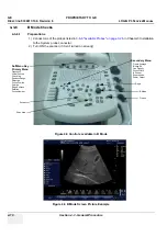
In the control Panel press the power On/Off key the led color will turn in Green color & the system will
boot.
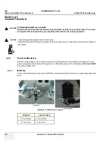
Figure 4-1 Connect AC adapter
CAUTION
SYSTEM REQUIRES ALL COVERS
Operate this unit only when all board covers and frame panels are securely in place. The covers
are required for safe operation, good system performance and cooling purposes.
NOTICE
Lockout/Tagout Requirements (For USA only)
Follow OSHA Lockout/Tagout requirements by ensuring you are in total control of the Power Cable on
the system.
LOGIQ P3
LOGIQ P3 BT10
A. Circuit Breaker
a. Circuit Breaker
B. Power Cable
b. Power Cable
Signed
Date
TAG
&
LOCKOUT
a
b

