GE PROPRIETARY
TO
GE
D
IRECTION
5308917-100, R
EVISION
8
LOGIQ P3 S
ERVICE
M
ANUAL
10-16
Section 10-7 - Electrical Safety Tests
10-7-3
Outlet Test - Wiring Arrangement
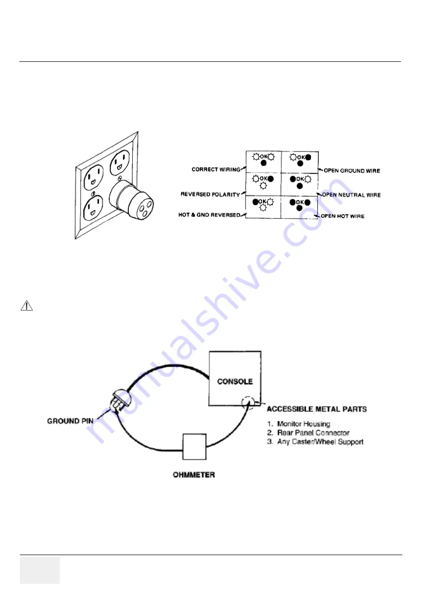
Test all outlets in the area for proper grounding and wiring arrangement by plugging in the neon outlet
tester and noting the combination of lights that are illuminated. Any problems found should be reported
to the hospital immediately and the receptacle should not be used.
10-7-4
Grounding Continuity
Measure the resistance from the third pin of the attachment plug to the exposed metal parts of the case.
The ground wire resistance should be less than
0.2
ohms. Reference the procedure in the IEC 601-1.1.
10-7-4-1
Meter Procedure
Follow these steps to test the ground wire resistance.
1.) Turn the LOGIQ P3 unit OFF.
2.) Plug the unit into the meter, and the meter into the tested AC wall outlet.
Figure 10-1 Typical Alternate Outlet Tester
CAUTION
Electric Shock Hazard. The patient must not be contacted to the equipment during this test
Figure 10-2 Ground Continuity Test


