Modifications reserved
Page 58/65
OPM_LPS_3UO_50K_60K_1US_V010.doc
Operating Manual
LP 33U Series 30 & 40 kVA
7.2.4 Separate (shutdown) a UPS unit from the Parallel System (System Redundancy)
One UPS unit of the
Parallel System
has to be turned Off, while the
load
is shared between the other
units supplying the parallel bus.
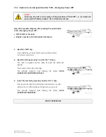
1. Disconnect the inverter, only on this unit, by pressing
“
Inverter OFF
”
( O ) key and hold until the
LED Inverter (7) turns OFF
.
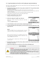
With
redundant system
, pressing the key OFF the
inverter
shuts down and it will stay OFF.
If by pressing the key
“O”
the
load
is transferred to the
utility
and the
inverter
remains operating, it means the
system is not redundant.
In this case is not possible to switch-OFF one unit without transferring the
load
on
utility
).
Load
supplied from
inverter(s)
of the other Unit(s) of the
Parallel System
.
2. Open the output switch Q1 only on this unit.
LED Alarms
is lit and the
LED Operation
is Off.
`
Home\Commands
COMMANDS
RESET TOTAL OFF
REQUEST TOTAL OFF
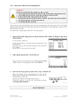
3. Perform the command “Total Off” only on this unit.
Perform the command
“Total Off”
by entering the screen (see
Section 6.5)
:
COMMANDS /
REQUEST TOTAL OFF
V
4. Switch OFF battery breaker only from battery cabinet belongs to this unit..
5.
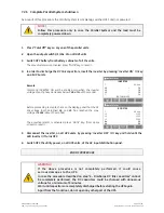
In order to discharge the DC link capacitors, insert the inverter by pressing
“
Inverter ON
”
( I ) key
only on this unit.
`
Home\Meter
INVERTER
f :
60.0
Hz
L1 :
7
V
L2 :
7
V
L3 :
7
V
T :
OK
SYNCHRONIZED
Remark
:
Command
INVERTER ON
will be enabled only when the inverter
voltage of each phase decreases below
7 Vac
(about 30 seconds).
`
Home\ Meter
BOOSTER
f :
60.0
Hz
L1 :
120
V
L2 :
120
V
L3 :
120
V
Vp :
5
V
Vn :
5
V
Before proceeding to step
6
, check on the display panel that the
DC
link voltage
(both polarities)
Vp
and
Vn
has reached the max.
voltage of
5 Vdc
(about 30 seconds).
The
acoustical alarm
is activated, press
“MUTE”
key (from Home
screen) to reset it.
6. Disconnect the inverter, only on this unit, by pressing
“
Inverter OFF
”
( O ) key and hold until the
LED Inverter (7) turns OFF.
7.
Switch OFF the utility power, only on this unit, at the AC input distribution panel.
END OF PROCEDURE
WARNING !
In case the unit should be disconnected and removed from the operating system, the
operation MUST BE PERFORMED BY QUALIFIED PERSONS.
If an intermediate unit must be disconnected from a parallel system pay attention do not
open the control bus: keep the plugs
J3
and
J4
connected to the board
“P16 - Connector
adapter RPA”
(See
Chapter 3.9.5
of
Installation Guide)
.
For any further intervention contact nearest
Service Center
.


