Modifications reserved
Page 63/66
OPM_LPS_3UO_80K_M10_1US_V010.doc
User Manual
LP33 Series 80 & 100 UL S1
7.2.8 Restore to normal operation after “EPO – Emergency Power Off”
NOTE !
Make sure the all units of the
Parallel System
to be status of the activation of “
EPO -
Emergency Power Off”
, i. e.
Q1
closed,
Q2
open and the
“Battery Breaker”
of the
Battery Cabinet
are ON (Pos.I).
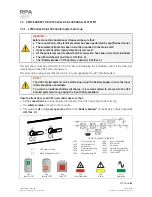
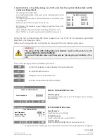
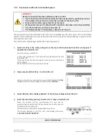
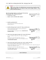
View of the
synoptic diagram
, on all UPS units, after pressing
the push-button “
EPO - Emergency Power Off”
:
•
All
Contactors
are open.
•
Booster, Inverter
and
Static-Switch
shutdown.
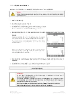
1. Reset
the
push-button
“
EPO
”
.
Press
MUTE
key to reset
Alarm and Acoustical alarm
.
LED Alarm
remains lit.
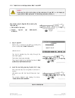
2.
Reset the UPS by pressing “Inverter OFF” ( O ) key on all UPS units.
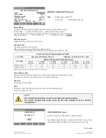
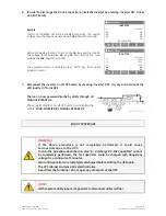
The load is supplied by the
utility
through the
automatic bypass
.
The
booster
starts automatically.
The
synoptic diagram
must display the status
“
LOAD SUPPLIED BY
AUTOMATIC BYPASS
”
.
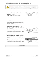
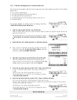
3. Insert the inverter by pressing
“
Inverter ON
”
( I ) key on first UPS unit
.
In case of sufficient output power, the output will transfer to
Inverter
.
LED Alarm
turns OFF and the
LED Operation
must be is lit.
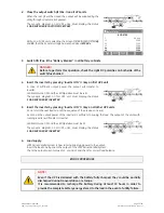
The
Synoptic diagram
, on first UPS unit, must display the status
“
LOAD SUPPLIED BY INVERTER
”
.
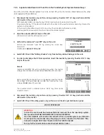
4. Insert the inverter by pressing
“
Inverter ON
”
( I ) key on all other UPS units
.
Do not start the next
inverter
until the sequence of the previous one end.
As soon as the output power of the
inverters
is sufficient to supply the
load
, the output of the units with
running
inverter
will transfer to
inverter
.
LED Alarm
turns OFF and the
LED Operation
must be lit.
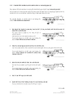
The
Synoptic diagram
, on all UPS units, must display the status
“
LOAD SUPPLIED BY INVERTER
”
.
END OF PROCEDURE

