Modifications reserved
Page 9/66
OPM_LPS_3UO_80K_M10_1US_V010.doc
User Manual
LP33 Series 80 & 100 UL S1
2 LAYOUT
2.1 LAYOUT
LP33 Series 80 & 100
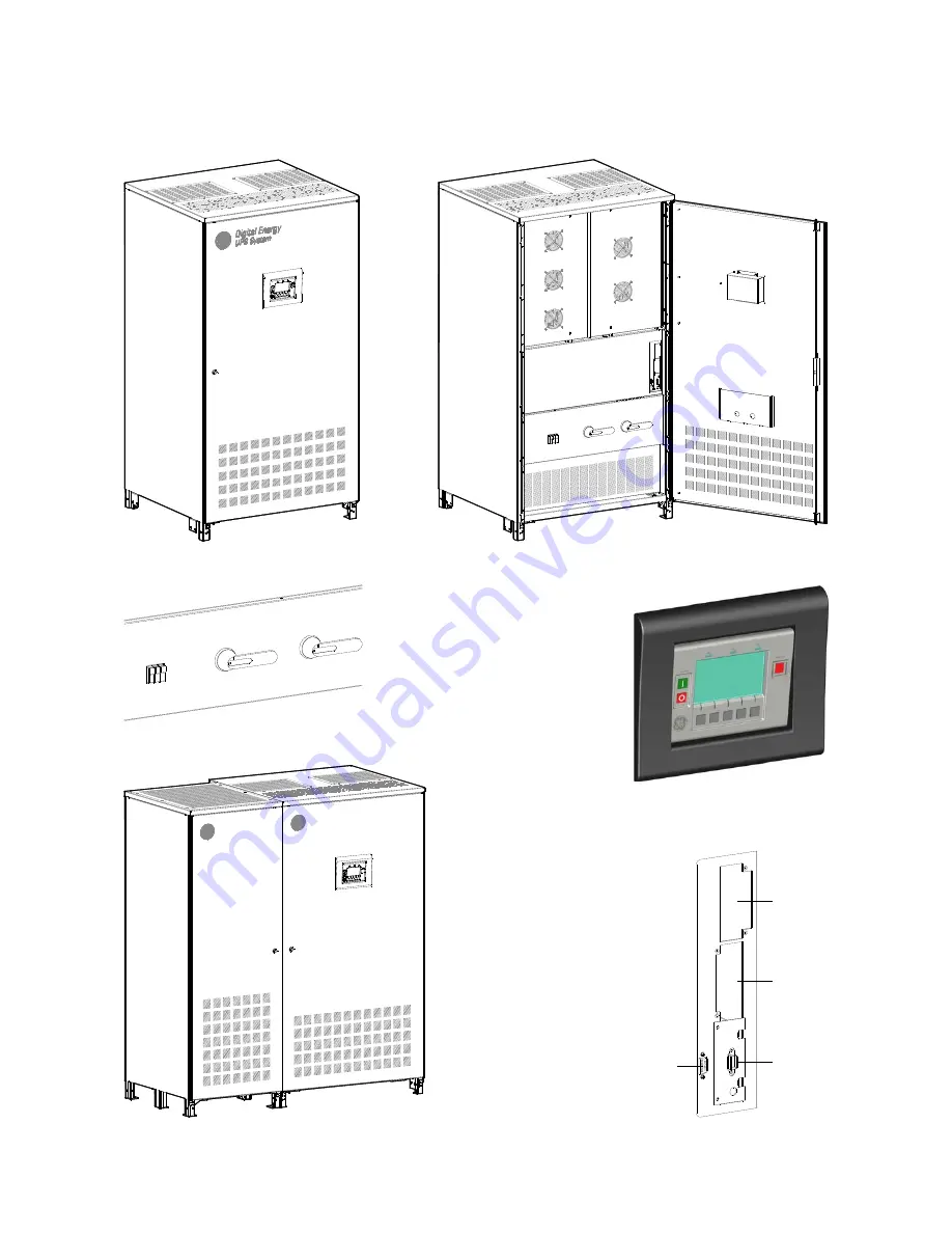
Fig. 2.1-1 General view – UPS only
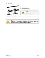
Q2
I ON
0 O
FF
Q1
I ON
0 O
FF
F11-12-13
Fig. 2.1-2 General view – UPS only - With front door open
Q2
I ON
0 OFF
Q1
I ON
0 OFF
F11-12-13
Fig. 2.1-3 Q1 & Q2 switches and F11-12-13 fuses
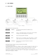
Fig. 2.1-4 Control panel
Battery System
Digital Energy
UPS System
Digital Energy
Fig. 2.1-6 General view – UPS with battery cabinet 26”/650mm
LP
S
33
U
_0
80
-1
0
0_
C
on
ne
ct
iv
ity
_0
1
RS232
RC
CI
SNMP
Fig. 2.1-5 Connectivity Rack


