30
BREAKER
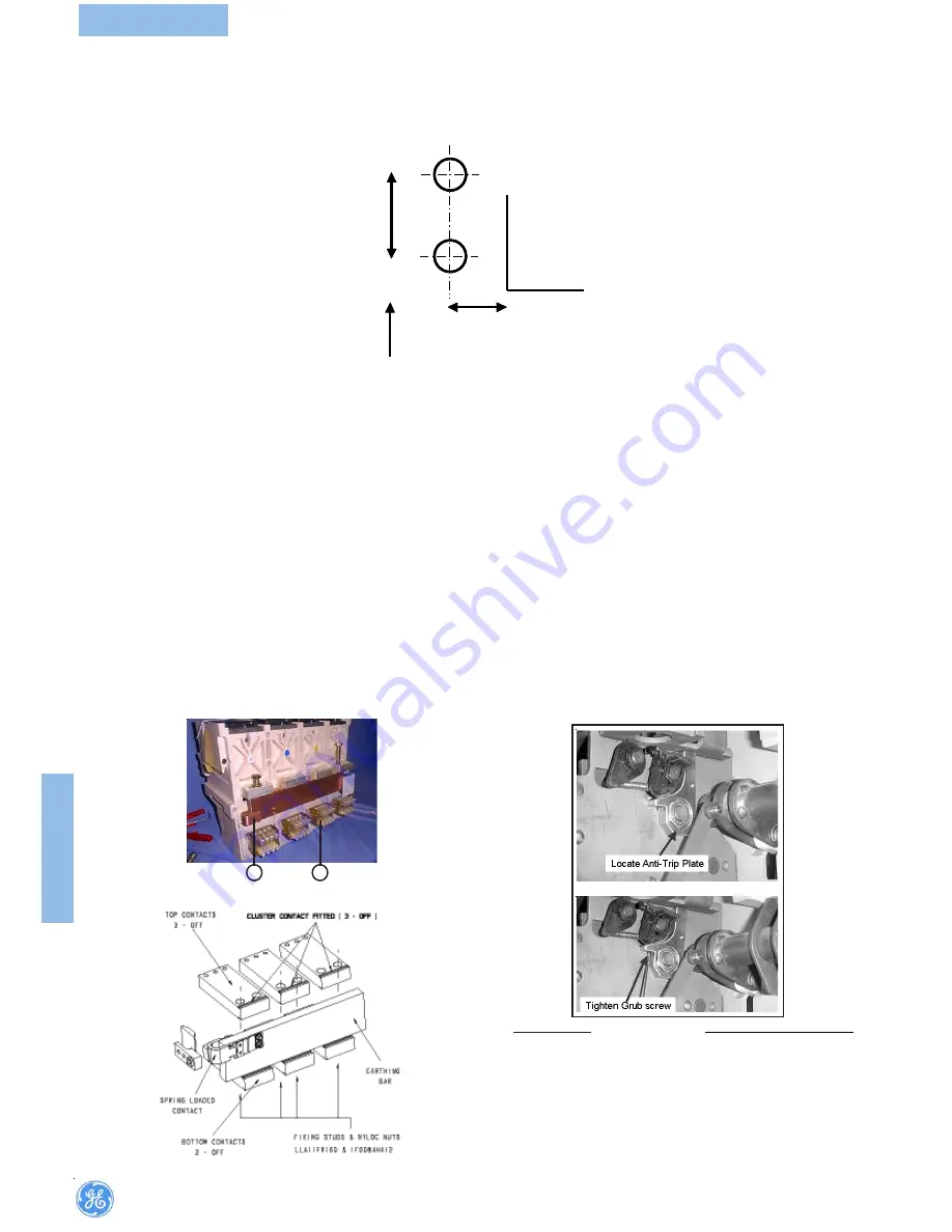
Door bracket location detail below (Fig.) is for right hand hinged switch board
doors. Drill two holes in the door for M5 clearance.
6.11 Busbar/Cable Earthing
Optional pack to enable earthing of circuit breaker terminals on busbar or
cable side contains:-
•
Isolating contact (cluster) pliers for removal of the main isolating con-
tacts.
•
Earthing bar with spring pressured earth contact . The bar is
reversible to fit top or bottom terminal sets **.
•
Necessary fixing bolts and washers.
•
Anti-trip plate*.
To earth the upper contact set:
(a) Remove the three upper contact clusters at the rear of the circuit
breaker, using the cluster pliers provided (Fig.).
(b) Position earthing bar below the three exposed terminals and loosely
tighten the M10 bolts (into the tapped earthing bar; one bolt per phase.
Tighten to 30Nm.
Note:
1.The spring loaded earthing contact should be facing left when viewed from
rear (Fig.).
2.*Available upon customer request
.
3.**Example shown below for the Bottom Terminal sets
Türwinkel (siehe Fig.) dargestellt für Tür mit Linksanschlag. Zwei Löcher für
M5 Befestigungsmaterial müssen gebohrt werden.
6.11 Erdung von Sammelschienen/Kabeln
Das optional erhältliche Set ermöglicht die Erdung der
Leistungsschalteranschlüsse auf Sammelschienen- oder
Kabelseite und enthält:
•
Isolierte Kontaktzange zum Abbau der Ausfahrkontakte.
•
**Erdungsschiene mit gefederten Erdungskontakt . Die Schiene
ist sowohl an den oberen wie unteren Schalteranschlüssen
montierbar.
•
Erforderliche Befestigungsschrauben und Scheiben
•
Auslöse -Blockierungsplatte*.
Erdung der oberen Anschlüsse:
(a) Entfernen der oberen Ausfahrkontakte auf der Rückseite des
Leistungsschalters mit der Kontaktzange (Fig.).
(b) Erdungsschiene unterhalb der drei freistehenden Anschlüsse
lose mit den M10 Schrauben fixieren (Gewindelöcher in der
Erdungsschiene vorhanden, eine Schraube pro Phase)
Anziehen mit Drehmoment 30Nm.
Hinweis:
1.Der gefederte Erdungskontakt muss sich links befinden (Schalter von
hinten gesehen, Fig.)
2.*Auf Anfrage
3.**Unten ist ein Beispiel für dieErdung der unteren Anschlüsse gezeigt
21mm
8mm
RH Hinged
Door Cut-out
F1,3P&4P -41.5
F1,3P&4P -101.5
21mm
21mm
8mm
8mm
RH Hinged
Door Cut-out
RH Hinged
Door Cut-out
F1,3P&4P -41.5
F1,3P&4P -101.5
F1,3P&4P -41.5
F1,3P&4P -101.5
Rechtsanschlag
Türausschnitt
1.Spring loaded earthing contact.
2.Cluster
1.
Gefederter Erdungskontakt.
2
.
Einfahrkontakte
2
1
FIT
TING
INSTRUCTION
*Anti-Trip Plate
*Auslöse -Blockierungsplatte
**Bottom Terminal sets
F2
Summary of Contents for M-Pact Plus
Page 65: ...65 DIMENSIONS ...
Page 66: ...66 DIMENSIONS ...
Page 67: ...67 DIMENSIONS ...
Page 68: ...68 DIMENSIONS ...
Page 69: ...69 DIMENSIONS ...
Page 70: ...70 DIMENSIONS ...
Page 71: ...71 DIMENSIONS ...
Page 72: ...72 DIMENSIONS ...
Page 73: ...73 DIMENSIONS ...
Page 74: ...74 DIMENSIONS ...
Page 75: ...75 DIMENSIONS ...
Page 76: ...76 DIMENSIONS ...
Page 77: ...77 DIMENSIONS ...
Page 78: ...78 DIMENSIONS ...
Page 79: ...79 DIMENSIONS ...
Page 80: ...80 DIMENSIONS ...
Page 81: ...81 DIMENSIONS ...
Page 82: ...82 DIMENSIONS ...
Page 83: ...83 DIMENSIONS ...
Page 84: ...84 DIMENSIONS ...
Page 85: ...85 DIMENSIONS ...
Page 86: ...86 DIMENSIONS ...
Page 87: ...87 DIMENSIONS ...
Page 88: ...88 DIMENSIONS ...
Page 89: ...89 DIMENSIONS ...
Page 90: ...90 DIMENSIONS ...
Page 91: ...91 DIMENSIONS ...
Page 92: ...92 DIMENSIONS ...
Page 93: ...93 DIMENSIONS ...
Page 94: ...94 DIMENSIONS ...
Page 95: ...95 DIMENSIONS ...
Page 96: ...96 DIMENSIONS 3200A 3200A ...
Page 97: ...97 DIMENSIONS 3200A 3200A ...
Page 98: ...98 DIMENSIONS 3200A 3200A ...
Page 99: ...99 DIMENSIONS 3200A 3200A ...
Page 100: ...100 ...
Page 101: ...101 ...
Page 102: ...102 ...
Page 103: ...103 ...
Page 104: ...104 ...
Page 105: ...105 ...
Page 106: ...106 ...
Page 107: ...107 ...
Page 108: ...108 3200 3200 ...
Page 109: ...109 ...
Page 112: ...112 DIMENSIONS W W W W Wiring M PR iring M PR iring M PR iring M PR iring M PRO O O O O ...
Page 116: ...116 APPENDIX ...
Page 125: ...125 APPENDIX ...


