background image

g

MAC™ 1200/MAC™ 1200 ST

Resting ECG Analysis System

(2018357-003 & 2013503-003 PWAs)

Service Manual

2012250-095         Revision D

GE Healthcare

Summary of Contents for MAC 1200

Page 1: ...g MAC 1200 MAC 1200 ST Resting ECG Analysis System 2018357 003 2013503 003 PWAs Service Manual 2012250 095 Revision D GE Healthcare ...

Page 2: ...l are subject to change without notice MAC and MUSE owned by GE Medical Systems Information Technologies Inc a General Electric company going to market as GE Healthcare All other marks are owned by their respective owners 2010 2014 General Electric Company All rights reserved CAUTION Software compatibility issue Attempting to download v6 2 software or later into 002 boards PN 2018357 001 2018357 0...

Page 3: ...s may not be appropriate for prior devices i e electromagnetic compatibility standards this device will not impair the safe and effective use of those previously distributed devices See user s information Exceptions The MAC 1200 resting ECG analysis system EMC Immunity Performance Users should be aware of known RF sources such as radio or TV stations and hand held or mobile two way radios and cons...

Page 4: ...Compliance 2 MAC 1200 resting ECG analysis system Revision D 2012250 095 Compliance For your notes ...

Page 5: ...ire Instrument 7 Mechanical Components 8 2 Functional Description 1 Basic Information 3 Switching Power Supply 4 PCB NC Battery Charge 5 Charging Circuit for the NC Battery 5 Battery Dependent Device Behavior 6 PCB Control CS_CI 7 Generation of Internal Power Supplies 7 Switch On Off Circuit 8 ECG Recording and Front End Processing 9 Controller Core 10 Real Time Clock 11 Memory 12 LCD Graphics Dis...

Page 6: ...Self Test 9 Error Codes 9 Recording Test 10 V24 Tests 11 Sending and Receiving 1 11 Send Test String to Device 2 11 Send and Receive with Device 3 12 Time and Date 13 Electrode Test 14 Time Constant Baseline Roll Filter 15 Setting the Device Model 16 Interpretation International Device Models Only 18 Pace Enhance 19 Serial Number 20 Ergometer Treadmills JAPAN Device Model Only 21 ACI TIPI US Devic...

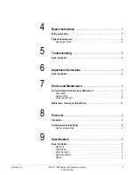
Page 7: ... Instructions 1 Basic Information 3 7 Service and Maintenance 1 Technical Inspections Preventative Maintenance 3 Visual Check 4 Test Functions 4 Safety Analysis Tests 8 Maintenance Cleaning and Disinfection 11 8 Parts List 1 Introduction 3 Field Replaceable Units FRUs 4 High Level Assemblies 4 9 Specifications 1 Basic Information 3 Recording 3 Printer Paper 3 Paper Transport 4 Membrane Keypad 4 Di...

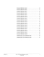
Page 8: ...ne 8 ECG Storage 8 Blocking 9 Electrode Monitoring 9 Text Input 9 Copy Function 9 Test 9 Power Supply 9 Mains Operation 10 Battery Operation 10 Operational Readiness 10 Operating Position 10 Environment 11 Recorder Dimensions 11 Weight 11 10 Drawings 1 Basic Information 2 High Level Assembly PN 101 168 01 38 Sheet 1 3 11 Drawings 3 High Level Assembly PN 101 168 01 38 Sheet 2 4 PCB Assembly Drawin...

Page 9: ...0 15 Schematic PN 2033914 033 Sheet 11 16 Schematic PN 2033914 033 Sheet 12 17 Schematic PN 2033914 033 Sheet 13 18 Schematic PN 2033914 033 Sheet 14 19 Schematic PN 2033914 033 Sheet 15 20 Schematic PN 2033914 033 Sheet 16 21 Schematic PN 2033914 033 Sheet 17 22 Schematic PN 2033914 033 Sheet 18 23 Schematic PN 2033914 033 Sheet 19 24 Schematic PN 2033914 033 Sheet 20 25 PCB Battery Charge CS_CSI...

Page 10: ...vi MAC 1200 resting ECG analysis system Revision D 2012250 095 ...

Page 11: ...Revision D MAC 1200 resting ECG analysis system 1 1 2012250 095 1 The Basics ...

Page 12: ...1 2 MAC 1200 resting ECG analysis system Revision D 2012250 095 For your notes ...

Page 13: ... person who uses maintains or troubleshoots this equipment Definitions The following formats are used in this manual to highlight various web viewer features and functions Black text Indicates keys on the keyboard text to be entered or hardware items such as buttons or switches on the equipment Italicized text Indicates software terms that identify menu items buttons or options in various windows ...

Page 14: ...itious The use of any real person s name is purely coincidental Revision History This manual has a revision letter located at the bottom of each page This revision letter changes whenever the manual is updated Revision A is the initial release of the document Table 1 Revision History PN 2012250 095 Revision Date Comments A 22 May 2007 Initial release of this manual B 31 August 2009 Updated schemat...

Page 15: ...rs three modes of operation ECGs acquired in automatic 12 lead mode can be transmitted to the MUSE or CardioSys system directly or via modem A NC battery with a charging circuit is integrated into the unit In addition a pump for the KISS system can be integrated into the instrument as a separate option NC battery with charging circuit is integrated in general Automatic mode with CSI protocol for t...

Page 16: ...the MAC 1200 resting ECG analysis system are listed below Switching power supply PCB Control CS_CI Printing unit Keypad 1 4 VGA graphics display monochrome Device Device Model Manufacturer ID Keypad Labeling Mains Voltage MAC1200 MAC1200 ST INT GE Medical Systems Icons International 230V MAC1200 MAC1200 ST Europe 2 GE Medical Systems Text International 230V MAC1200 MAC1200 ST USA GE Medical System...

Page 17: ...CGRAM Buffered RS232 Driver Keypad Interface Display Interface Display Supply Motor Control Thermal Pinhead Control Device On Off Control Logic Supply 5 V 3 3 V Analog Supply Printhead Supply Real Time Clock Buffered Controller Core ECG Acquisition and Conditioning NC Battery PCB NC Battery Charge Switching Power Supply 26 5 V Line Power Input with Fuse Printing Unit Thermal Printhead Motor LCD Gr...

Page 18: ...pper shell accommodates the keypad which is connected to the PCB Control CS_CI via a 26 pin connector The MAC 1200 resting ECG analysis system can be opened by releasing 5 screws at the bottom of the lower shell opening the paper flap and lifting up the upper shell a little bit to remove the keypad cable from the PCB Control CS_CI The upper shell then can be removed completely To replace the NC Ba...

Page 19: ...Revision D MAC 1200 resting ECG analysis system 2 1 2012250 095 2 Functional Description ...

Page 20: ...2 2 MAC 1200 resting ECG analysis system Revision D 2012250 095 For your notes ...

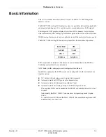
Page 21: ...unctional Description Basic Information Basic Information The block circuit diagram of the entire instrument in Chapter 1 Block Circuit Diagram of Entire Instrument and the functional blocks of circuit diagram sheets P plans describe the individual functional blocks ...

Page 22: ... Switching Power Supply The switching power supply generates the fundamental device voltage for the PCB Control CS_CI and for the PCB NC Battery Charge It has the following input specifications Input voltage range 85 264 Vac Line frequency range 47 65 Hz The output voltage is 26 5 Vdc the maximum load is 1 5 A ...

Page 23: ...he charging process depending on the status of the battery and the status of the device Charging Circuit for the NC Battery An integrated charging device is used to charge the battery During charging it monitors the battery voltage function and switches over from rapid charging to trickle charging Applying the line power to the MAC 1200 resting ECG analysis system or insertion of the battery activ...

Page 24: ...ate 3 Battery depleted no line power supply device is switched on Device inoperative State 4 Battery full no line power supply device is switched on Device fully operative When battery is almost depleted the LEDBAT signal is activated to indicate that the device should be charged by connecting to the line power supply If the operation is continued without line power MAC 1200 1200 ST will shut down...

Page 25: ...on of the voltage controller both supplies are based on the same voltage controller The output voltage is determined by appropriate dimensioning of the voltage divider at the feedback input of the voltage controller Standby Supply 5 VSTB and 3 3 VSTB The standby supply 5VSTB supplies the ON OFF Control the 3 3 VSTB buffers the patient ECG memory when the device is turned off Both supplies are gene...

Page 26: ...or Standby state when line power is connected can be achieved as follows Pressing the On Off button When the control core activates the signal DEV_OFF When the voltage control applies the signal REG_OFF_ because the battery voltage gets too low during battery operation The Voltage Control controls the battery voltage during battery operation The signal BATT_LEV2 indicates that the battery charge h...

Page 27: ...g is a set of chips comprising 3 ASICs Pace detection is realized by a separate circuit Every disconnected electrode is detected by a special AC measurement which allows higher impedance between electrode and patient N common mode compensation ensures suppression of interference at the same time serving to improve the in phase suppression of the input electrodes To protect patients the ECG recordi...

Page 28: ...eneration KAPWR generated from the 3 3 V logic supply or from a battery when device is off used for buffering the RTC Counter Register The clock generation for the MPC855T is realized by a quartz oscillator with 32 768 KHz The system clock CLOCKOUT is adjusted with the internal PLL register The system frequency is 25 MHz The watchdog reset generation is implemented separately in an integrated syst...

Page 29: ...he device control battery charging and display control signals The status register contains information on the device hardware configuration and the state of the battery charge Real Time Clock With software version 6 two options for the real time clock are supported The software checks for an external real time clock chip X13 on PWA control This chip is available with Index G of PWA Control CS_CI ...

Page 30: ... state DRAM Type SDRAM 3 3 V supply Organization 4Mbit X 16 8Mbyte Wait States 0 wait state Patient ECG Memory Type Buffered SRAM 3 3 V supply Organization 512Kwords X 16 bits Wait States 1 wait state Configuration Memory The configuration memory is part of the program memory Flash With special hardware and software protection facilities write access to the Flash is only possible in the defined co...

Page 31: ...trast Contrast adjustment of the display is accomplished with the contrast voltage V0 The level of V0 is controlled with the PWM signal BLCD_CONTR from the timer module of the MPC855T In addition the contrast voltage is temperature compensated Backlight The LCD backlight converter for the CCFL tube is located on the PCB Control CS_CI too The backlight converter is generated from the 5 V logic powe...

Page 32: ...ated with the next column till all columns have been activated Printhead Control The printhead controller takes on the complete control of the 216 mm thermal printhead with a line width of 200 mm The output rate to the printhead is 1000 second The resolution in the Y direction is 8 dots mm in the X time axis up to 40 dots mm Thermal Printhead Dot Control The MPC855T prepares a complete dot column ...

Page 33: ...eating via the signal STROBE reenabled In addition a continuous reduction of the heating duration occurs with increasing printhead temperature resulting in a regular typeface throughout the entire temperature range Motor Control Paper transportation for the speeds 5 mm s 25 mm s and 50 mm s is driven by a stepping motor The stepping motor is controlled by an integrated stepping motor driver circui...

Page 34: ...ls RTS and CTS Software handshake with XON XOFF Transmission speeds from 4800 57600 Baud Maximum input voltage range 15 V Minimum driver output voltage 5 V Maximum ESD interface protection 10 kV The MAC 1200 resting ECG analysis system provides a remote start input on the RS 232 interface The MAC 1200 resting ECG analysis system US device additionally provides a modem power supply output on the RS...

Page 35: ...no longer used in MAC1200 units equipped with 003 boards The modem power supply is now integrated onto the main board 2018357 003 and 2013503 003 The main board generates a supply voltage of 8 Vdc to operate a special GE modem direct on the RS 232 interface on the MAC 1200 device without the need for an external power supply for the modem ...

Page 36: ... mechanically The function of the individual pins is given in the table The definition as an input output is seen with reference to PCB Control CS_CI POSUP Interface to the PCB NC Battery Charge This interface has the supply for battery charging charging control and status signals and the battery voltage from the PCB NC battery charge Connector denotation BATT Type Male multipoint connector 2 x 10...

Page 37: ... on the contrast selected The voltage supply for the CCFL tube of the display is provided separately via the connector BL CAUTION Do not touch High AC voltage Pin Number Signal Input Output Function Definition 1 24V Output Supply battery charging 2 24V Output Supply battery charging 3 24V Output Supply battery charging 4 Code Coding Pin 5 NC 6 GND24V Common Ground 7 GND24V From power supply 8 GND2...

Page 38: ...he control data to the printhead is transferred via the flexible PCB Printhead Connection plugged into the connector TPC_DAT on the PCB Control CS_CI Connector denotation TPC_DAT Type Male connector 1 x 20 pin 180 Printhead Supply The printhead is supplied through a 6 pin connection cable plugged to the connector TPC_PO on the PCB Control CS_CI Connector denotation TPC_PO Type Multipoint connector...

Page 39: ...an interface for the production test of the processor core and the memory In addition the Flash memories can be programmed with this interface Connector denotation JTAG Type Male connector 2 x 5 pin 180 Pin 7 coding pin The function of the individual pins is given in the table below The definition as an input output is seen with reference to PCB Control CS_CI JTAG Pin Number Signal Input Output Fu...

Page 40: ...nector 2 x 5 pin 180 Pin 4 coding pin The function of the individual pins is given in the following table The definition as an input output is seen with reference to PCB Control CS_CI ISP Pin Number Signal Input Output Function Definition 1 ISP_SCLK Input Serial ISP Clock 2 GND Logic Ground 3 ISP_MODE Input ISP Mode Select 4 NC Not connected 5 NC Input Not connected 0 ISP enable 6 ISP_SDI Input Se...

Page 41: ...ed earth conductor The mains input is a wide range input from 95 Vac 240 Vac The mains input module contains the two primary fuses When replacing these fuses the following points need to be observed Replacement by factory or servicing agent only Disconnect mains plug Replacement only with the original fuses For the patient input the mechanics of the patient input of the MAC 500 is used so the pati...

Page 42: ...put 8 V is available on pin 6 additionally Connector denotation RS232 Type 9 pin sub D female Mark II with 4 40 UNC inserts The function of the individual pins is given in the table below The definition as an input output is seen with reference to PCB Control CS_CI RS232 Table 2 RS232 Pin Position Pin Number Signal Input Output Function Definition 1 NC 2 RXDE Input RS232 Data In 3 TXDE Output RS23...

Page 43: ...pe 15 pin sub D female J1 Table 3 EKG Pin Position Pin Number Signal Input Output Function Definition 1 C2 Input Chest lead V2 2 C3 Input Chest lead V3 3 C4 Input Chest lead V4 4 C5 Input Chest lead V5 5 C6 Input Chest lead V6 6 Shielding Output Shielding AVSS 7 Cable Input Identification patient cable used 0 patient cable used 8 Cable identification Input 5 10 pin or 12 pin cable used 0 12 pin ca...

Page 44: ...The following operating modes are not implemented in the MAC 1200 resting ECG analysis system No SpO2 No spirometry No late potentials no RR variability No phono no US Doppler A scope output is not available No analog inputs No ECG trigger output Lead acid accumulators cannot be used Primary cells cannot be used ...

Page 45: ...Revision D MAC 1200 resting ECG analysis system 3 1 2012250 095 3 System Test Function ...

Page 46: ...3 2 MAC 1200 resting ECG analysis system Revision D 2012250 095 For your notes ...

Page 47: ... to override all other passwords is SYSTEM All messages displayed during the self test are in English The functions for the system test are mostly menu guided Some tests require special auxiliary resources These include interface testers or PC connection cables signal generators etc These auxiliary resources are described in the various test descriptions ...

Page 48: ...ll device variants except US and Pharma US version2 2 Applies to US and Pharma device variants Key Test Performed Key Test Performed 1 Display test 1 Display test 2 Keyboard 2 Keyboard 3 Motor test 3 Motor test 4 Test results 4 Test results 5 Recording test 5 Recording test 6 V24 tests 6 V24 tests 7 Time and date 7 Time and date 8 Electrode test 8 Electrode test D Device model D Device model H Int...

Page 49: ...l The contrast setting can always be adjusted as described above cursor keys Table 2 Display Test Key Test Performed Function 1 Test pattern Pressing this key generates a vertical stripe pattern Each subsequent pressing generates the inverse display of its predecessor 2 Clear display All display pixels are inactive 3 Restore menu The initial display test menu is displayed 4 Display illumination Th...

Page 50: ...ressed this key or its function is displayed This can either occur by a triple character display e g AAA or as a text e g CURS_UP Moreover pressing the B key tests the bleeper audible sound The keys ALT and SHIFT only in combination with another key The E key terminates this test and simultaneously initiates a self test Table 3 Keyboard Test Key Test Performed B Bleeper Test E End ...

Page 51: ...et the required speed and the motor is set into motion with Start Stop A marking pulse is set once every second The running speed can then be calculated or its accuracy checked from the distance between marking pulses Pressing a key that is not included in this menu will return you to the initial display menu Table 4 Motor Speed Test Key Test Performed Format Speed Speed selection motor Start Stop...

Page 52: ...llowing information Time and date Device serial number Device model Software release ECG time constant Battery voltage Test results Memory used ROM RAM Base address Size Following output the initial display menu reappears automatically The identification of the Hardware Version is given by the item Remote Control yes no No indicates Hardware Version V 1 0 no remote control yes indicates Hardware V...

Page 53: ...re detected a message appears on the display after the test indicating the possible errors The following error codes are used to identify the error Error Codes The following error codes appear on the display together with the message Self test failed ERROR_CODES 0 Reserved 1 VEKT error in vector table 2 DRAM DRAM error 3 SRAM SRAM error 4 Reserved 5 Reserved 6 Reserved 7 Reserved 8 ROMB ROM error ...

Page 54: ...cording Test The recording test is activated by pressing the 5 key A window with 2 channels is displayed The selected speed and sensitivity are displayed Terminate with any key Table 5 Motor Speed Test Key Test Performed Speed Selects the speed Start Stop Starts and stops a real time 2 channel recording ...

Page 55: ...g of the RS232 signal path for transmitting and receiving including RS232 driver and connector This test requires an RS232 connector with an internal bridge from pin 2 RXDE to pin 3 TXDE Depending on the result of the test the following message appears If test result is OK Out Hello world In Hello world If an error occurs Out Hello world In ERROR In Send Test String to Device 2 In this test a remo...

Page 56: ...ould be connected as described in Send Test String to Device 2 After pressing the 3 key a test string is sent to the remote station The following message appears on the display Transmitting Hello world Receiving A subsequent input at the remote station is sent back to the device and displayed there Moreover it should be noted that an input must take place within 10 seconds and the input terminated...

Page 57: ...se instructions for checking and setting the time and date Pressing the 7 key calls up the following display To set time or date select the corresponding time or date field by pressing the return key A cursor is not displayed while numbers are entered Table 7 Time and Date Time hh mm 18 25 29 Date dd mm yyyy 03 03 2003 X End ...

Page 58: ...s displayed Electrode OK or disconnected is displayed as follows Status 0 Electrode OK Status 1 Electrode disconnected With the P key the pace electrode can be selected The selected pace electrode is displayed The status cable indicates if a cable is connected to the patient ECG input or not Table 8 Electrode Test Electrode Test Terminate with any key Select pace electrode key P Pace electrode LA ...

Page 59: ...st Function Time Constant Baseline Roll Filter Time Constant Baseline Roll Filter Beginning with software release V5 2 the time constant can no longer be set in the service mode It is accessible in the user mode under System Setup Baseline roll filter 0 04 Hz 0 08 Hz 0 16 Hz ...

Page 60: ... the device model affects the selection of the output formats and languages available and can switch the program for interpretation from HEART to 12 SL or vice versa The default configuration settings e g override function yes no line filter 50 60 Hz are also affected The device model configured during manufacture should only be changed when deemed really necessary Table 9 Device Model 1 INT 2 USA...

Page 61: ...interpretation program was configured differently beforehand as described in Interpretation International Device Models Only on page 3 18 NOTE When configuring the device model saved ECGs are not lost If a new device model is selected the program for interpretation is switched over When printing the saved ECGs the display in the status line is related to the currently enabled program for interpret...

Page 62: ...ry The required program for Interpretation is selected by pressing the appropriate key 1 or 2 Quit the selection menu by pressing the X key Quit the self test with the X key MAC 1200 resting ECG analysis system configures the appropriate items and initiates a cold start automatically Thus when the device is rebooted automatically all the new settings are adopted NOTE When configuring the device mo...

Page 63: ...em 3 19 2012250 095 System Test Function Pace Enhance Pace Enhance Beginning with software release V5 2 the Pace Enhance mode can no longer be set in the service mode It is accessible in the user mode under System Setup Pace Enhancement YES or NO ...

Page 64: ...rial number of the device is displayed by pressing the N key The serial number is only displayed and cannot be changed The serial number is entered during the manufacturing process After replacing the PCB Control CS_CI during the power up sequence the serial number of the device has to be entered Terminate with the X key ...

Page 65: ...s JAPAN Device Model Only Ergometer Treadmills JAPAN Device Model Only Enable or disable ergometer treadmill functionality in the Japanese device model by pressing the O key The following display image appears Table 12 Ergometers Treadmills 1 YES drivers are available in Stress Test mode 2 NO not available ...

Page 66: ...ng display image appears NOTE ACI TIPI can be DISABLED in the service mode at any time independently of the the Patient Data Setup screen However if chest pain is enabled selected Yes in the Patient Data Setup screen and ACI TIPI is disabled then the chest pain option will removed from the Patient Data Setup menu When a new patient is input the chest pain question is still asked Table 13 ACI TIPI ...

Page 67: ...trials by CROs and then sent out to trial sites to collect data The Pharma option of the MAC 1200 can be password protected HIGH SECURITY Password protection is enabled in the system setup High Security NOTE The Pharma and HIGH SECURITY options appear only if the device has been configured as a Pharma device High Security provides the option of password protecting use of the MAC 1200 unit Any devi...

Page 68: ...3 24 MAC 1200 resting ECG analysis system Revision D 2012250 095 System Test Function Pharma For your notes ...

Page 69: ...Revision D MAC 1200 resting ECG analysis system 4 1 2012250 095 4 Repair Instructions ...

Page 70: ...4 2 MAC 1200 resting ECG analysis system Revision D 2012250 095 For your notes ...

Page 71: ...nnect the mains plug when the device is open Before replacing the primary fuses in the power input module the device should also be switched off and the mains plug disconnected For replacing components only the original GE components mentioned in the spare parts list may be used When replacing electronic components implement ESD protection Return replaced PCBs in ESD packaging only Defective NC ba...

Page 72: ...rside of the device 2 Open the paper feed flap 3 Carefully raise the upper shell of the housing 4 Disconnect the keypad cable by opening the connector KEYB on the PCB Control The display remains in the lower shell of the casing During reassembly ensure that no cables are pinched Replacing the Primary Fuses in the Mains Input Module WARNING Only use fuses indicated on the rating label See Chapter 8...

Page 73: ... 095 Repair Instructions Replacing Components 3 Pull forward on lower part of connector port and small plastic tray will pop out with fuses 4 Remove fuses 5 Align and insert new fuses in plastic fuse tray 6 Position plastic fuse tray and snap back into position ...

Page 74: ...ts Replacing the Keypad 1 Open the device as described in Opening the Device on page 4 4 2 Replace with new Keypad FRU Assembly by connecting keypad connector in front of unit 3 Place the plastic spacer tubes back in the handle 4 Align upper shell to lower unit 5 Insert and fasten 5 screws to lower unit ...

Page 75: ...in accordance with the applicable legal stipulations or returned to the factory Batteries returned to the factory should be labeled For disposal 3 Before putting in the new battery insert plug BATT_IN Push in battery compartment secure by pressing on the fastening catch Replacing the PCB Battery Charge 1 Open the device 2 Open the battery compartment and disconnect the battery connector BATT_IN Se...

Page 76: ...dered 6 Also check whether the connection LOET1 of the backlight inverter is soldered correctly 7 Insert new PCB fix the fastening screws and plug in connectors 8 Connect keypad in the upper shell to connector KEYB 9 Close connector on PCB control 10 Set the upper shell on to the lower shell Tighten the 5 fastening screws 11 Contact your local service representative to download the software 12 Ent...

Page 77: ... replace the graphics display 1 Open the device 2 Open connector HOS and release the flat ribbon cable of the display 3 Undo the screws of both plastic display holders 4 Shift the display 2 mm in the direction to the handle and lift up display and holders 5 Disconnect the plug HOS_BL To reassemble reverse these instructions Adjust the contrast with the new display ...

Page 78: ...4 10 MAC 1200 resting ECG analysis system Revision D 2012250 095 Repair Instructions Replacing Components For your notes ...

Page 79: ...Revision D MAC 1200 resting ECG analysis system 5 1 2012250 095 5 Troubleshooting ...

Page 80: ...5 2 MAC 1200 resting ECG analysis system Revision D 2012250 095 For your notes ...

Page 81: ...ypad via connector KEYB on PCB Control plugged in correctly It there a 26 5 V on the connector POSUP If no mains switching power supply defective If yes PCB control defective or keypad defective The green power lamp LED is on but device still cannot be switched on Is the PCB control defective Is the keypad defective Device cannot be switched on when running on battery power Is the battery depleted...

Page 82: ...des are described in Chapter 3 Self Test The error codes refer to the PCB Control and should be noted as information for the service center MAC 1200 Fails to Give Printout No Paper Transport Perform the following test in the 6 lead operating mode Is paper available Is paper correctly inserted Are there paper transport problems jam Is the paper feed flap correctly engaged on both sides After pressi...

Page 83: ... paper feed flap is only engaged on one side MAC 1200 Prints but only Baselines are Printed Out Are the electrodes applied correctly Are electrode cables plugged into the patient trunk cable terminal box correctly Is the patient trunk cable defective e g RL defective Are there contact problems at the patient input connector of the MAC1200 If not The PCB control defective ...

Page 84: ...5 6 MAC 1200 resting ECG analysis system Revision D 2012250 095 Troubleshooting Basic Information For your notes ...

Page 85: ...Revision D MAC 1200 resting ECG analysis system 6 1 2012250 095 6 Adjustment Instructions ...

Page 86: ...6 2 MAC 1200 resting ECG analysis system Revision D 2012250 095 For your notes ...

Page 87: ... Basic Information Basic Information For the MAC 1200 resting ECG analysis system no adjustment of components is required When PCB Control CS_CI or the graphics display has been exchanged the display contrast should be adjusted to an optimum contrast ratio as described in the user manual ...

Page 88: ...6 4 MAC 1200 resting ECG analysis system Revision D 2012250 095 Adjustment Instructions Basic Information For your notes ...

Page 89: ...Revision D MAC 1200 resting ECG analysis system 7 1 2012250 095 7 Service and Maintenance ...

Page 90: ...7 2 MAC 1200 resting ECG analysis system Revision D 2012250 095 For your notes ...

Page 91: ...see Enclosure Leakage Current Test on page 7 9 Measure the patient leakage current see Patient Leakage Current Test on page 7 9 WARNING The following checks may only be performed by persons whose training knowledge and practical experience enable them to carry out such checks reliably and correctly The operational and functional reliability of the device is checked using the information in this ch...

Page 92: ... analysis system are used for the tests See Chapter 3 System Test Function for details Connect MAC 1200 resting ECG analysis system up to the mains the green LED for standby must glow Switch the device on the self test runs automatically no error message should appear When the self test has finished the device is in the automatic mode the yellow LED indicating disabled operating mode should still ...

Page 93: ...utput Test Results as detailed in Chapter 3 Test Results Main parameters All memory stores free from error ASIC test O K Sample rate 1000 Printhead voltage 18 V battery charge O K Printout clearly legible and without any lapses or interference RS 232 Interface Test Carry out the Interface Test item 1 Transmitting and receiving as detailed in Chapter 3 V24 Tests ...

Page 94: ...e Date and time Recording speed Sensitivity Active filter e g 50 60 Hz 40 20 Hz ADS Frequency range of the recording The heart rate of 60 bpm 2 bpm appears on the display and is printed out on the recording Activate the square wave function on the ECG simulator at 1 mV Using the lead scrolling key select lead II The square wave pulse trace must correspond in amplitude with the displayed 1 mV refer...

Page 95: ... simulator Activate the Automatic 12 lead mode in the MAC 1200 resting ECG analysis system device to be tested without activating it by pressing the Start key Ensure that each disconnected electrode is displayed correctly and that an acoustic alarm signal sounds Checking the Charge Status of the NC Battery The NC battery can be checked as follows Discharging the battery followed by charging up com...

Page 96: ... connector according to the following description Protective Earth Resistance Test The power cord is to be included in the protective earth resistance test This test determines whether the device has a power ground fault The protective earth resistance from power connector to any protective earth connected exposed conductive part is measured Specification of test circuit AC current source 50 Hz 60...

Page 97: ...nts have to be done under the following conditions refer to the electrical diagram Polarity switch NORM and RVS GND switch GND open S1 closed The test has failed if the measured values are greater than the following N C S F C 100 µA 500 µA 300 µA UL requirements Electrical Diagram for Enclosure Leakage Current Test Patient Leakage Current Test This test performs a leakage current test under single...

Page 98: ...ured values are greater than 50 µA Electrical Diagram for Patient Leakage Current Test For the protection of the test person the following values of resistor R may be used Type BF 22 kOhm 120 to 130 V 47 kOhm 220 to 240 V Type CF 100 kOhm 220 to 240 V 022A Safety Tester M GND Power Cord Patient Cable or Test Plug NORM High GND Low Unit Under Test Power Cord R RVS ...

Page 99: ...tion is performed in accordance with the Cleaning Disinfection and Maintenance chapter of the operator manual for the MAC 1200 resting ECG analysis system Applications requiring extensive recordings may result in deposits on the thermal array printhead which normally do not have any adverse effect on the printing quality This can be removed with a soft lint free cloth soaked in an alcohol based cl...

Page 100: ...7 12 MAC 1200 resting ECG analysis system Revision D 2012250 095 Service and Maintenance Maintenance Cleaning and Disinfection For your notes ...

Page 101: ...Revision D MAC 1200 resting ECG analysis system 8 1 2012250 095 8 Parts List ...

Page 102: ...8 2 MAC 1200 resting ECG analysis system Revision D 2012250 095 For your notes ...

Page 103: ...ceable units listed in this chapter cover two versions of the product MAC 1200 with the 002 board MAC 1200 with the 003 board Most of the FRUs listed in this chapter apply to both versions of the product Any FRUs that are specific to one of these product configurations have appropriate notes added to the Description ...

Page 104: ...Russia Basic unit with Battery With Pump 10116829 MAC 1200 Europe 2 Basic unit with Battery Without Pump 10116830 MAC 1200 Europe 2 Basic unit with Battery With Pump Table 2 MAC 1200 ST Part Number Description 10116831 MAC 1200 ST International Basic unit with Battery Without Pump 10116835 MAC 1200 ST International Basic unit with Battery With Pump 10116834 MAC 1200 ST Japan Basic unit with Batter...

Page 105: ...sting ECG analysis system Operator s Manual Norwegian 2012250 046 MAC 1200 resting ECG analysis system Operator s Manual Russian 2012250 047 MAC 1200 resting ECG analysis system Operator s Manual Japanese 2012250 048 MAC 1200 resting ECG analysis system Operator s Manual Chinese 2012250 049 MAC 1200 resting ECG analysis system Operator s Manual Finnish 2012250 050 MAC 1200 resting ECG analysis sys...

Page 106: ...case with keypad and filter pane INT 1 2006894 001 Upper case with keypad and filter pane INT 2 2006895 001 Upper case with keypad and filter pane USA 2006896 001 Upper case with keypad and filter pane JAPAN 2006897 001 Upper case with keypad and filter pane RUS 2000088 001 Filter pane complete with glue frame 43252554 Sign GE Medical Systems Information Technologies Hellige 43252555 Sign GE Medic...

Page 107: ...part no 30344746 43252213 Cover plate for Motor 30343829 Mark Reader old Used up to PN 101082178 optional sensor 2001495 001 Mark Reader new Used from PN 101082179 and higher optional sensor 30344271 Thermal Printhead 38802910 PCB Printhead connection 43252209 Plastic holder for Printhead left side 43252210 Plastic holder for Printhead right side 41515439 Pressure spring for Printhead 50465725 Met...

Page 108: ...95 001 ASSY WIRE MODEM SUPPLY MAC1200 2013503 003 Chinese MAC1200 003 PWA with v6 2 loaded NOTE The following parts are no longer used on MAC1200 s shipping with the 003 PWA 2000771 001 PCB MODEM SUPPLY CS_M 2001795 001 ASSY WIRE MODEM SUPPLY MAC1200 Table 11 MAC 1200 PWAs version 002 board Part Number Description 2000072 002 Spare PCB Control with remote start for MAC 1200 NOTE 002 board only Bac...

Page 109: ... 93011858 PCB power supply 91208449 Fuse T 1 25 A 92916717 Battery 3 V 0 255 Ah 30344291 Pump 12 V Standard 38803125 PCB Pump Table 13 Display Module Graphics Part Number Description 2007630 001 Assembly LCD Module Graphic replace display PN 93011717 43252565 LCD holder right side 43252564 LCD holder left side Table 14 Wire Set Part Number Description 38327399 Cable assembly MAC 1200 resting ECG a...

Page 110: ...dem 25 pin connector cable modem CardioSmart 22337804 Connection cable from MAC 1200 to Modem 25 pin with supply US only 22336604 Connection cable from MAC 1200 resting ECG analysis system to EC1200 22336802 Connection cable from MAC 1200 ST to TM400 22338002 Connection cable from MAC 1200 ST to Ergoline 900 800 2006795 001 Connection cable from MAC 1200 ST to Variobike 500 22339003 Connection cab...

Page 111: ...Revision D MAC 1200 resting ECG analysis system 9 1 2012250 095 9 Specifications ...

Page 112: ...9 2 MAC 1200 resting ECG analysis system Revision D 2012250 095 For your notes ...

Page 113: ...mm 6 Lead 12 channels 16 mm 12 Lead Writing width 200 mm maximum Recorder settings date time and entered patient name are annotated in the margin of the recording strip With appropriate software documentation of analysis results in the respective operating mode Resolution of the recording Vertical 8 dots mm Horizontal 25 mm at 25 mm s Printer Paper GE CONTRAST Z fold pad 150 pages per pad equivale...

Page 114: ...k Function keys for all routine operations Alphanumeric keyboard for entry of text Display Graphics display with 24 x 40 characters contrast adjustment Resolution of 320 x 240 pixels with display backlighting Indicators LEDs For mains power battery status and start stop function Automatic Functions Automatic functions assist and facilitate operation by the following Automatic control of lead selec...

Page 115: ...nals referred to neutral electrode 50 M up to 60 Hz Dynamic range for differential signals between any two electrode connections for AC voltage 10 mV for superimposed DC voltage polarization voltage 600 mV Dynamic range for common mode signals referred to neutral electrode 1 V referred to chassis 263 V AC rms Quiescent input current via any electrode connection for 1 kW termination referred to neu...

Page 116: ... 15 V maximum Output voltage range 5 V minimum Interface protected from electrostatic discharge for 10 kV maximum Pin Assignment of Data Port Remote Start Hardware Paper feed via remote control connection depending on selected operating mode External make contact referred to chassis via circuit reference Source impedance Ri 300 Contact dwell 100 ms Non destructive load 10 V ESD interface protectio...

Page 117: ...operating mode Arrhy 100 Hz IEC Signal sampling rate 1000 s Resolution referred to the input 5 µV Output rate to recorder 2000 s For all leads gain adjustment in four steps 40 20 10 5 mm mV With active muscle filter low pass characteristic 3 dB drop of the amplitude frequency response at approximately 40 or 20 Hz With active AC line filter detection and compensation of periodic 50 or 60 Hz frequen...

Page 118: ...d group or of all leads determines the gain setting Automatic adjustment range 5 to 40 mm mV Amplitude range 6 channels 18 to 31 mm Baseline Automatic adjustment of the baseline to the optimal recording range in dependence of the signal amplitude Anti Drift System ADS Cubic Spline Automatic compensation of baseline fluctuations caused by polarization voltage fluctuations at the lead electrodes del...

Page 119: ... Input Patient and user data as well as comments can be entered via the panel keyboard and are annotated on the recording strip Copy Function After ECG recording in 12 Lead Mode copies of the ECG can be printed from memory and or transferred to a MUSE CV system configurable Test Automatic performance test upon power up including verification of the signal path starting at the signal input Stored t...

Page 120: ...ery Operation Type nickel cadmium Rated battery voltage 18 V Rated battery capacity 1 3 Ah Fully charged battery sufficient for up to 50 12 Lead Mode 1 page ECGs if unit is only switched on to record the ECGs Battery charge time approximately 4 hours Minimum charge time for one 12 Lead Mode ECG 10 minutes Battery life approximately 2 to 3 years replacement by service only Lithium battery for built...

Page 121: ... pressure between 700 and 1060 hPa between 20 67 and 31 3 inches Hg Transport and Storage Temperature between 30 and 60 C 22 and 140 F including battery Relative humidity between 25 and 95 Atmospheric pressure between 500 and 1060 hPa between 14 76 and 31 3 inches Hg Recorder Dimensions Width 370 mm 14 5 in Height 95 mm 3 7 in Depth 320 mm 12 6 in include handle Weight Approximately 5 6 kg 12 3 lb...

Page 122: ...9 12 MAC 1200 resting ECG analysis system Revision D 2012250 095 Specifications Basic Information For your notes ...

Page 123: ...Revision D MAC 1200 resting ECG analysis system 10 1 2012250 095 10 Drawings ...

Page 124: ... Manual PN 2012250 023 for drawings that apply to the MAC 1200 with the 002 PWA board Drawing Number Description 101 168 01 38 High Level Assembly Drawing 2033914 027 PCB Assembly Drawing 2033914 033 Schematic 20 pages 2018357 003 PCB Control CS_CI 388 032 90 P sheet 1 388 032 90 R sheet 1 PCB Battery Charge CS_CI 388 032 90 PCB Battery Charge CS_CSI ...

Page 125: ...Drawings High Level Assembly PN 101 168 01 38 Sheet 1 Revision A MAC 1200 resting ECG analysis system 10 3 2012250 095 High Level Assembly PN 101 168 01 38 Sheet 1 Not required with 003 board D ...

Page 126: ...Revision A MAC 1200 resting ECG analysis system 10 4 2012250 095 Drawings High Level Assembly PN 101 168 01 38 Sheet 2 High Level Assembly PN 101 168 01 38 Sheet 2 Not required with 003 board ...

Page 127: ...Drawings PCB Assembly Drawing PN 2033914 027 Revision A MAC 1200 resting ECG analysis system 10 5 2012250 095 PCB Assembly Drawing PN 2033914 027 ...

Page 128: ...Revision A MAC 1200 resting ECG analysis system 10 6 2012250 095 Drawings Schematic PN 2033914 033 Sheet 1 Schematic PN 2033914 033 Sheet 1 ...

Page 129: ...Drawings Schematic PN 2033914 033 Sheet 2 Revision A MAC 1200 resting ECG analysis system 10 7 2012250 095 Schematic PN 2033914 033 Sheet 2 ...

Page 130: ...Revision A MAC 1200 resting ECG analysis system 10 8 2012250 095 Drawings Schematic PN 2033914 033 Sheet 3 Schematic PN 2033914 033 Sheet 3 ...

Page 131: ...Drawings Schematic PN 2033914 033 Sheet 4 Revision A MAC 1200 resting ECG analysis system 10 9 2012250 095 Schematic PN 2033914 033 Sheet 4 ...

Page 132: ...Revision A MAC 1200 resting ECG analysis system 10 10 2012250 095 Drawings Schematic PN 2033914 033 Sheet 5 Schematic PN 2033914 033 Sheet 5 ...

Page 133: ...Drawings Schematic PN 2033914 033 Sheet 6 Revision A MAC 1200 resting ECG analysis system 10 11 2012250 095 Schematic PN 2033914 033 Sheet 6 ...

Page 134: ...Revision A MAC 1200 resting ECG analysis system 10 12 2012250 095 Drawings Schematic PN 2033914 033 Sheet 7 Schematic PN 2033914 033 Sheet 7 ...

Page 135: ...Drawings Schematic PN 2033914 033 Sheet 8 Revision A MAC 1200 resting ECG analysis system 10 13 2012250 095 Schematic PN 2033914 033 Sheet 8 ...

Page 136: ...Revision A MAC 1200 resting ECG analysis system 10 14 2012250 095 Drawings Schematic PN 2033914 033 Sheet 9 Schematic PN 2033914 033 Sheet 9 ...

Page 137: ...Drawings Schematic PN 2033914 033 Sheet 10 Revision A MAC 1200 resting ECG analysis system 10 15 2012250 095 Schematic PN 2033914 033 Sheet 10 ...

Page 138: ...Revision A MAC 1200 resting ECG analysis system 10 16 2012250 095 Drawings Schematic PN 2033914 033 Sheet 11 Schematic PN 2033914 033 Sheet 11 ...

Page 139: ...Drawings Schematic PN 2033914 033 Sheet 12 Revision A MAC 1200 resting ECG analysis system 10 17 2012250 095 Schematic PN 2033914 033 Sheet 12 ...

Page 140: ...Revision A MAC 1200 resting ECG analysis system 10 18 2012250 095 Drawings Schematic PN 2033914 033 Sheet 13 Schematic PN 2033914 033 Sheet 13 ...

Page 141: ...Drawings Schematic PN 2033914 033 Sheet 14 Revision A MAC 1200 resting ECG analysis system 10 19 2012250 095 Schematic PN 2033914 033 Sheet 14 ...

Page 142: ...Revision A MAC 1200 resting ECG analysis system 10 20 2012250 095 Drawings Schematic PN 2033914 033 Sheet 15 Schematic PN 2033914 033 Sheet 15 ...

Page 143: ...Drawings Schematic PN 2033914 033 Sheet 16 Revision A MAC 1200 resting ECG analysis system 10 21 2012250 095 Schematic PN 2033914 033 Sheet 16 ...

Page 144: ...Revision A MAC 1200 resting ECG analysis system 10 22 2012250 095 Drawings Schematic PN 2033914 033 Sheet 17 Schematic PN 2033914 033 Sheet 17 ...

Page 145: ...Drawings Schematic PN 2033914 033 Sheet 18 Revision A MAC 1200 resting ECG analysis system 10 23 2012250 095 Schematic PN 2033914 033 Sheet 18 ...

Page 146: ...Revision A MAC 1200 resting ECG analysis system 10 24 2012250 095 Drawings Schematic PN 2033914 033 Sheet 19 Schematic PN 2033914 033 Sheet 19 ...

Page 147: ...Drawings Schematic PN 2033914 033 Sheet 20 Revision A MAC 1200 resting ECG analysis system 10 25 2012250 095 Schematic PN 2033914 033 Sheet 20 ...

Page 148: ... x4 x5 Revision No Not equipped in Version Marquette Hellige GmbH D 79007 Freiburg Date Name ISSUED APPROVED DRAWN Date Name REVISIONS Index x1 388 032 90 Schematic 1998 3 12 5 A B C D A03 USER_CAE_B cardiosmart_ci batload_ci design 388 032 90 D01 ECO 062727 ECO 062920 03 08 98 VRP 23 09 98 VRP 24 06 99 HAW 31 07 98 VRP 31 07 98 NTS N Schnurr Akku Ladung CS_CI 1 1 26 01 00 MSG F67267 ...

Page 149: ...Drawings PCB Battery Charge CS_CSI PN 388 032 90 Sheet 2 Revision A MAC 1200 resting ECG analysis system 10 27 2012250 095 PCB Battery Charge CS_CSI PN 388 032 90 Sheet 2 ...

Page 150: ......

Page 151: ...edical Systems Information Technologies GmbH Munzinger Straße 5 D 79111 Freiburg Germany Tel 49 761 45 43 0 Fax 49 761 45 43 233 Asia Headquarters GE Medical Systems Information Technologies Asia GE China Co Ltd 1 Huatuo Road Zhangjiang Hi tech Park Pudong Shanghai People s Republic of China 201203 Tel 86 21 3877 7888 Fax 86 21 3877 7451 www gehealthcare com ...

Reviews: