background image

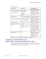
Electromagnetic Compatibility (EMC)

EMC Immunity Test (cont'd.)

Immunity Test

Compliance
Test Level

Compliance
Level

Electromagnetic
Environment–Guidance

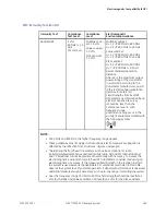
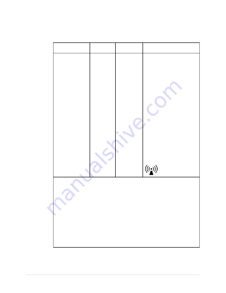
Radiated RF

3 V/m
80 MHz to 2.5
GHz
@ 2 Hz mod.

Multilink Lead
set: 3.0 V/m

Value Lead set:
3.0 V/m

KISS Lead set:
1.0 V/m

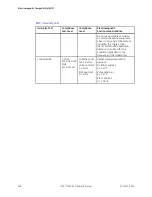
Multilink Lead Set:

d = 1.2 √P 80 MHz to 800 MHz
d = 2.3 √P 800 MHz to 2.5 GHz

Value Lead Set:

d = 1.2 √P 80 MHz to 800 MHz
d = 2.3 √P 800 MHz to 2.5 GHz

KISS Lead Set:

d = 3.5 √P 80 MHz to 800 MHz
d = 7 √P 800 MHz to 2.5 GHz

Recommended separation
distance:
where

P

is the maximum output

power rating of the transmitter
in watts (W) according to the
transmitter manufacturer, and

d

is the recommended separation
distance in meters (m).
Field strengths from fixed RF
transmitters, as determined by an
electromagnetic site survey:

a

should be less than the

compliance level in each
frequency range

b

Interference may occur in the

vicinity of equipment marked with
the following symbol:

NOTE:

• At 80 MHz and 800 MHz, the higher frequency range applies.

• These guidelines may not apply in all situations. Electromagnetic propagation is

affected by the reflection from structures, objects, and people.

a

Field strengths from fixed transmitters, such as base stations for radio

(cellular/cordless) telephones and land mobile radio, AM and FM radio broadcast,
and TV broadcast cannot be predicted theoretically with accuracy. To assess the
electromagnetic environment due to fixed RF transmitters, consider conducting an
electromagnetic site survey. If the measured field strength in the location in which
the system is used exceeds the applicable RF compliance level listed in this table,
observe the system to verify normal operation. If abnormal performance is observed,
additional measures may be necessary, such as re-orienting or relocating the system.

• Over the frequency range 150 KHz to 80 MHz, field strengths should be less than 3

V/m for Multilink and Value Lead Sets, and less than 1 V/m for the KISS Lead Sets.

2053535-003C

MAC™ 2000 ECG Analysis System

169

Summary of Contents for MAC 2000

Page 1: ...GE Healthcare MAC 2000 ECG Analysis System Service Manual Software Version 1 1 2053535 003 Revision C English 2013 General Electric Company All Rights Reserved ...

Page 2: ...ry CDL located at www gehealthcare com documents and click Cardiology To access Original Equipment Manufacturer OEM manuals go to the device manufacturer s Web site Service Manual Language Information WARNING EN This service manual is available in English only If a customer s service provider requires a language other than English it is the customer s responsibility to provide translation services...

Page 3: ...cemanual findes kun på engelsk Hvis en kundes tekniker har brug for et andet sprog end engelsk er det kundens ansvar at sørge for oversættelse Forsøg ikke at servicere udstyret medmindre denne servicemanual har været konsulteret og er forstået Manglende overholdelse af denne advarsel kan medføre skade på grund af elektrisk mekanisk eller anden fare for teknikeren operatøren eller patienten WAARSCH...

Page 4: ...oder des Patienten durch Stromschläge mechanische oder sonstige Gefahren kommen ΠΡΟΕΙΔΟΠΟΙΗΣΗ GR Το παρόν εγχειρίδιο σέρβις διατίθεται στα αγγλικά μόνο Εάν το άτομο παροχής σέρβις ενός πελάτη απαιτεί το παρόν εγχειρίδιο σε γλώσσα εκτός των αγγλικών αποτελεί ευθύνη του πελάτη να παρέχει υπηρεσίες μετάφρασης Μην επιχειρήσετε την εκτέλεση εργασιών σέρβις στον εξοπλισμό εκτός εάν έχετε συμβουλευτεί κα...

Page 5: ...i 警告 JA このサービスマニュアルは英語版しかありません サービスを担当される業者が英語以外の言語を要求される場合 翻訳作業はその業 者の責任で行うものとさせていただきます このサービスマニュアルを熟読し 十分に理解をした上で装置のサービスを 行ってください この警告に従わない場合 サービスを担当される方 操作員あるいは患者が 感電 や機械的又はその他の危険により負傷する可能性があります 경고 KO 본 서비스 지침서는 영어로만 이용하실 수 있습니다 고객의 서비스 제공자가 영어 이외의 언어를 요구할 경우 번역 서비스를 제공하는 것 은 고객의 책임입니다 본 서비스 지침서를 참고했고 이해하지 않는 한은 해당 장비를 수리하려고 시도하 지 마십시오 이 경고에 유의하지 않으면 전기 쇼크 기계상의 혹은 다른 위험으로부터 서비스 제 공자 운영자 혹은 환자에게...

Page 6: ... mecânicos ou outros AVISO PT PT Este manual técnico só se encontra disponível em inglês Se a assistência técnica do cliente solicitar estes manuais noutro idioma é da responsabilidade do cliente fornecer os serviços de tradução Não tente reparar o equipamento sem ter consultado e compreendido este manual técnico O não cumprimento deste aviso pode provocar lesões ao técnico ao utilizador ou ao pac...

Page 7: ...nosti poškoduje ponudnik storitev operater ali bolnik ADVERTENCIA ES Este manual de servicio sólo existe en inglés Si el encargado de mantenimiento de un cliente necesita un idioma que no sea el inglés el cliente deberá encargarse de la traducción del manual No se deberá dar servicio técnico al equipo sin haber consultado y comprendido este manual de servicio La no observancia del presente aviso p...

Page 8: ...о інженера користувача даного обладнання або пацієнта внаслідок електричного шоку механічного ушкодження або з інших причин невірного обслуговування обладнання CẢNH BÁO VI Tài Liệu Hướng Dẫn Sửa Chữa chỉ có bản tiếng Anh Nếu các đơn vị cung cấp dịch vụ cho khách hàng yêu cầu một ngôn ngữ nào khác tiếng Anh thì khách hàng sẽ có trách nhiệm cung cấp các dịch vụ dịch thuật Không được sửa chữa thiết b...

Page 9: ...patibility 19 Legal Notice 19 Supplies and Accessories 19 Responsibility of the Manufacturer 20 Responsibility of the Purchaser Customer 20 Product and Packaging Information 20 Training 28 Equipment Identification 28 Product Label 29 Serial Number Format 29 Device Address Label and Rating Plate 30 Product Codes 30 Service Information 31 Service Requirements 31 Warranty Information 31 Additional As...

Page 10: ...unications Tests 55 Testing the Patient Leadwires 59 Printing a Service Report 60 Updating the Software 60 Formating the Flash Memory 68 Opening a Command Prompt 70 4 Maintenance Recommended Maintenance 71 Required Tools and Supplies 71 FRU Replacement Procedures 72 High Level FRU Identification 72 Preparing the System for FRU Replacement 73 Battery 74 Device Covers 75 Power Supply 91 Power Inlet ...

Page 11: ...013 155 Display and O Rings 2066261 014 155 Display Overlay and O Rings 2066261 015 155 Cover Top and Plastic Parts 1 2066261 016 156 Door Sensor and Plastic Parts Printer Paper Tray 2066261 017 156 Paper Sensor 2066261 018 156 Print Head Assy 2066261 019 156 Static Brush 2066261 020 157 KISS Pump 2066261 021 157 Internal Modem 2066261 022 157 Keypads Non Stress 157 Keypads Stress 158 Barcode Scan...

Page 12: ... 167 Recommended Separation Distances 170 C Technical Specifications System Specifications 171 Acquisition Processing and Performance 173 Operating Modes Features and Options 175 D WiFi Country List Allowable Channels 177 12 MAC 2000 ECG Analysis System 2053535 003C ...

Page 13: ...ce intended to be used by or under the direct supervision of a licensed healthcare practitioner using surface electrodes to acquire analyze display and record information for adult and pediatric populations in a hospital medical professional s facility clinics physician s office or outreach centers NOTE Pediatric populations are defined as patients between the ages of 0 and 15 years The MAC 2000 E...

Page 14: ...d in this manual is considered abnormal use of this system and could result in injury data loss or a voided warranty Safety Conventions A Hazard is a source of potential injury to a person property or the system This manual uses the terms DANGER WARNING CAUTION and NOTICE to point out hazards and to designate a degree or level of seriousness Familiarize yourself with the following definitions and ...

Page 15: ...ider s work area WARNING MAGNETIC AND ELECTRICAL INTERFERENCE Magnetic and electric fields can interfere with the acquisition of ECG readings Make sure that all peripheral components operated in the vicinity of the device comply with the relevant EMC requirements X ray equipment MRI devices radio systems cellular phones and so forth are possible sources of interference because they may emit higher...

Page 16: ... with clinical findings A qualified physician must overread all computer generated tracings WARNING POOR SIGNAL QUALITY Improper skin preparation can cause poor signal quality during the ECG recording Careful skin preparation is the key to an interference free ECG WARNING IMPROPER USE This is a prescriptive device This equipment is intended for use by or under the direct supervision of a licensed ...

Page 17: ...rmful ingress of liquids IP20 The IP code for this device is IP20 Non protected This device is ordinary equipment enclosed equipment without protection against ingress of liquids Degree of safety of application in the presence of flammable anesthetic mixture with air or with oxygen or with nitrous oxide Equipment is not suitable for use in the presence of a flammable anesthetic mixture with air or...

Page 18: ...between or within 5 or 40 µV whichever is greater Frequency Response meets AAMI EC11 3 2 7 2 requirements using testing methods A and D Frequency response is between or within 10 between 0 67 and 40 Hz and between 0 and 10 for 20 ms 1 5 mV triangular input Modulating Effects in Digital Systems This device uses digital sampling techniques that may produce some variation in amplitudes of Q R and or ...

Page 19: ...al Biocompatibility The parts of the system described in this manual that come into contact with the patient during the intended use including all accessories fulfill the biocompatibility requirements of the applicable standards If you have questions in this matter contact your GE Healthcare representative Legal Notice GE Healthcare software contains several fields that can be filled in before per...

Page 20: ...ate local state and other government regulations The equipment is used in accordance with the instructions for use Responsibility of the Purchaser Customer The customer is responsible for providing appropriate desks chairs electrical wall outlets network connections and analog phone lines and for locating any of the system components described in this manual in compliance with all local state and ...

Page 21: ...ator manual 4 On the shipping package Environmental symbols required for shipping 5 On the shipping package Battery Shipping Label FRAGILE Lithium Ion batteries can cause fire if damaged 6 On the shipping package The shipping label Symbol Descriptions The following table describes symbols or icons that may be on the device or its packaging Not all of the symbols defined in the table apply to your ...

Page 22: ...der of a physician 12SL Indicates the device uses the Marquette 12SL ECG Analysis Program to analyze and interpret ECG readings IPxy IP Code Ingress Protection Rating Classifies and rates the degree of protection provided against the intrusion of solid objects such as body parts like hands and fingers dust accidental contact and liquids The first numeral x represents the degree of protection again...

Page 23: ...ies the terminal of a protective earth ground electrode or any terminal that is intended for connection to an external conductor for protection against electric shock in case of a fault Non ionizing Electromagnetic Radiation Indicates that the equipment emits elevated potentially hazardous levels of non ionizing radiation electromagnetic energy for diagnosis or treatment Follow Instructions For Us...

Page 24: ...ching into area or servicing As a warning sign this symbol is identified by a yellow background black triangular band and a black symbol WARNING HAND CRUSHING HAZARD This device contains moving parts that could crush the user s hand Keep hands clear of the device while it is in operation Disconnect power before reaching into or servicing the device As a warning sign this symbol is identified by a ...

Page 25: ...aching into the equipment can cause personal injury Do not place hands into any openings As a general prohibition sign this symbol is identified by a white background red circular band and slash and a black symbol WARNING ENVIRONMENTAL OR HEALTH HAZARD Incinerating the device or product could present a risk to the environment or human health Do not incinerate this device or product As a general pr...

Page 26: ...possible environmental or health hazard NOTE If the device contains less than the maximum concentration of restricted substances the symbol contains a lowercase e This is also referred to as China RoHS Japan RoHS Indicates the device or product meets the regulations limit or ban for specific substances in new electronic and electric equipment in Japan The Green Mark with the G indicates the produc...

Page 27: ...not indicate that your product was certified by that symbol s governing body and is listed for reference only To identify which organizations have certified your device refer to the labeling on your device or its packaging Certification Symbol Description UL Mark Indicates compliance with applicable Underwriters Laboratories requirements UL Listed Mark Indicates compliance with international or re...

Page 28: ...hnical and safety requirements following testing by Technischer Überwachungs Verein Technical Inspections Organization Training This manual is intended as a supplement to not a substitute for thorough product training If you have not received training on the use of the system you should request training assistance from GE Healthcare To see available training go to the GE Healthcare training Web si...

Page 29: ...g support for your product The serial number format is shown in the following illustration Serial Number Format Item Name Description 1 Product Code Three letter code that uniquely identifies the product line See Product Codes on page 30 for more information 2 Year Manufactured Two digit code identifying the year the device was manufactured Values range from 00 to 99 For example 00 2000 04 2004 05...

Page 30: ...Description 1 Product description 2 Country of origin 3 Symbols See Symbol Descriptions on page 21 for a description of the symbols used on this label 4 Electrical rating of the device 5 Manufacturer name and address Product Codes The product code identifies specific system platforms You can identify the product code using the serial number listed on the product label located in one of the followi...

Page 31: ...bility to report the need for service to GE Healthcare or to one of their authorized agents Additional Assistance GE Healthcare maintains a trained staff of application and technical experts to answer questions and respond to issues and problems that may arise during the installation maintenance and use of this system Contact your local GE Healthcare representative to request additional assistance...

Page 32: ... within the string Enter Indicates that you must press the Enter or Return key on the keyboard Do not type Enter The greater than symbol or right angle bracket is a concise method to indicate a sequence of menu selections For example the statement From the main menu select System Setup Options to open the Option Activation window replaces the following 1 From the main menu select System to open th...

Page 33: ...operation Exercise This mode is for exercise stress testing RR Analysis This mode is for RR intervals analysis The basic system prints 6 or 12 leads of ECG and provides optional transmission and reception of ECG data to and from a central ECG cardiovascular information system You can also upgrade it with software options such as 12 lead ECG measurement and interpretive analysis Hardware Overview T...

Page 34: ...lect menu options on the screen 4 Printer door push button Opens the printer door 5 Printer Printer door Prints reports Rear View Rear View of Device Item Name Description 1 SD card slot Connection for Secure Digital SD card This system supports SD cards formatted for the FAT or FAT16 file systems 2 LAN connection RJ45 network connector 34 MAC 2000 ECG Analysis System 2053535 003C ...

Page 35: ...SE CardioSoft or MUSE systems 5 COMM B port Serial connector for stress devices bicycle ergometer or treadmill 6 Phone jack RJ11 connector from the internal modem to an analog phone line 7 AC Power Cord connection Standard connector for the AC power cable Side View Side View of Device Item Name Description 1 KISS connection Connection port for the optional KISS Pump system 2 ECG Patient Cable conn...

Page 36: ...ttery compartment 3 Printed Wiring Assembly PWA 4 KISS connector port 5 ECG patient cable connector port 6 SD Card port 7 RJ45 LAN connection port 8 USB ports 2 9 COMM A port 10 COMM B port 11 RJ11 Phone port to Internal Modem 12 Power Supply 36 MAC 2000 ECG Analysis System 2053535 003C ...

Page 37: ...dicates the device is plugged in and receiving power 4 Leads key Scrolls through the leads and allows you to select the display formats for the lead sequence 5 ECG key Acquires and prints a 12 lead ECG 6 Rhythm key Prints real time continuous rhythm 7 Writer Stop Stops the printing function 8 Trimpad Cursor Control keys Provides movement through menus and windows For description on using the trimp...

Page 38: ...lt key Switches between different input methods for Japanese and Korean keyboard languages 13 Space bar Enters a space in the text As a secondary function it moves through the menu lists 14 Option key Use to enter special characters on non English keyboards 15 ESC escape Closes a window on a screen 16 Shift key Use to enter a capital letter For example press Shift p to type a capital P Stress Keyp...

Page 39: ...anually increases the treadmill speed or ergometer load 7 Grade á á á stress key Grade up Increases the elevation of the treadmill 8 Tmil stress key Starts the treadmill during the test 9 Tmil stress key Stops the treadmill during the test 10 Gradeâ â â stress key Grade down Decreases the elevation of the treadmill 11 Speed W stress key Speed Load down Manually decreases the treadmill speed or erg...

Page 40: ...eration This section describes the block diagram hardware firmware architecture and the product interfaces for this system Block Diagram The following diagram illustrates the basic layout of this system 40 MAC 2000 ECG Analysis System 2053535 003C ...

Page 41: ...Product Overview 2053535 003C MAC 2000 ECG Analysis System 41 ...

Page 42: ...d with the AD DC module through an EMI filter The AC DC is a 65W power supply accepting a wide input AC voltage and delivering 24 DC to the main board KISS pump An internal KISS pump is powered by the main board The suction connector is terminated next to the patient connector in the assembly Product Interfaces This system offers the following interfaces for connecting to external devices for data...

Page 43: ...lems and can be useful as part of system checkout procedures Accessing Service Setup Use the following procedure to access Service Setup 1 Power on the system by pressing the Power button 2 On the Main Menu press System Configuration 3 Press More More Service Setup A window opens prompting you to enter the Service password 4 Type prod and press OK NOTE If the keypad does not include the letters pr...

Page 44: ...ings 1 On the Service Setup menu select Device Settings and press Enter The following window opens 2 In the Serial Number field type the serial number of the device 3 Select the appropriate language from the Keyboard Language list 4 Press Save Event Log Event logging is a way to track system errors warnings and informational messages 44 MAC 2000 ECG Analysis System 2053535 003C ...

Page 45: ...t logging select the Key Event Logging check box or To disable event logging deselect the Key Event Logging check box 3 Select a level of severity to log from the Log Level list Log Level Severity Log Level What is logged to the Event Log Error Logs only errors Warning Logs errors and warnings Information Logs errors warnings and information messages 4 Press Save to save your settings 2053535 003C...

Page 46: ..._0 log is copied to a log directory on the SD card NOTE To access the log file insert the SD card into an SD card reader that is connected to a computer with a Windows operating system and a text editor such as Notepad or WordPad If GE Healthcare technical service requests the Event Log for troubleshooting an issue send the file as an email attachment System Diagnostics Use the System Diagnostics ...

Page 47: ... to the appropriate section for the test you need to perform Testing the Display Use the Display Test to determine if the display pixels are working properly 1 Open the DIAGNOSTIC TESTS window as described in System Diagnostics on page 46 2 Select Display Test The Start Test window opens 2053535 003C MAC 2000 ECG Analysis System 47 ...

Page 48: ...the down arrow on the Trimpad repeatedly 8 Verify that the color band pattern red green blue white scrolls down the screen Pass the test if the pattern is replicated without discoloration 9 Press the first function key again to cycle through the solid color pane red green blue white 10 For each pane check for black pixels Pass the test if no more than 4 black pixels are observed on any single colo...

Page 49: ...as described in Display Assembly on page 108 Testing the Speaker Use the Speaker Test to determine if the speaker is working properly 1 Open the Diagnostic Tests window as described in System Diagnostics on page 46 2 Select Speaker Test 3 Listen for a brief audible tone coming from the speaker The following window opens 4 Select pass or fail If you heard an audible tone press Yes If you did not he...

Page 50: ...keys continue to press keys that already have an asterisk on the screen and verify that the screen representation of the key is highlighted with each subsequent key press A key passes if the key on the screen highlights with each repeated key press 5 When the test is done press Shift F6 The following window opens 6 Select pass or fail If every key passes the tests press Yes If any key fails the te...

Page 51: ... the test result and press Cancel 4 If the result of the Acquisition Module Test was Failed replace the main PWA as described in PWA on page 120 Checking the Battery Status Use the Battery Test to determine the status of the Lithium Ion battery You must perform this test while running on battery power 1 Disconnect the device from AC power and wait at least one minute 2 Open the Diagnostic Tests wi...

Page 52: ...nt levels of safety protection It is not recommended to charge Lithium ion batteries above 45 C 113 F If the device is operating at a high ambient temperature and the battery temperature exceeds the recommended operating conditions charging stops automatically Under such conditions turn off the device and let it cool before restarting charging You can extend the battery life by reducing the bright...

Page 53: ...wable tolerance of 1 0 mm the test passes If this criteria is not met the test fails d If the test passed press Yes If the test failed press No 4 Repeat the previous step for the other speed tests The pass fail criteria for each of the remaining tests are as follows 25mm s Speed Test If one cycle of the square wave spans 25 mm on paper measured from corner to corner of the wave with an allowable t...

Page 54: ... gaps in any of the lines printed Up to 5 mm of blank paper is allowable at the top and bottom of the page When the page is done printing the following window opens If there are no gaps in the lines on the printed report press Yes If there are gaps in the lines on the printed report press No 6 When all writer tests are completed press Cancel to close the window 7 If one or more of the writer tests...

Page 55: ...per motor Replace the roller in the printer door assembly Refer to Printer Door on page 103 Faulty printer assembly Replace the printer assembly Refer to Printer Module Assembly on page 94 Writer paper does not move Faulty PWA Replace the main PWA Refer to PWA on page 120 Faulty cables in printer assembly 1 Check for proper cable assembly between the printer and PWA 2 Replace the printer assembly ...

Page 56: ... Back Test 5 Perform the COM Port Loop Back Test on COM B a Use the paper clip to short pins 2 and 3 on the COM B connector b Select COM B press Enter The results of the COM Loop Back Test for COM B are displayed c Note the results of the COM Loop Back Test for COM B 6 When the test is done press Esc or Cancel to close the results window If either test failed replace the main PWA module as describ...

Page 57: ...splayed in the window and you are sure the system is connected to an active network the test fails Network Unavailable 5 When the test is done press Esc or Cancel to close the results window If the test failed replace the main PWA as described in PWA on page 120 Testing the Internal Modem Use the Modem Test to test the internal modem 1 Connect the device to an active analog phone line Ensure that ...

Page 58: ...ncel to close the results window Testing the USB Port Use the USB Test to test the USB port 1 Open the Diagnostic Tests window as described in System Diagnostics on page 46 2 Connect a USB keyboard to the USB port on the rear panel of the device NOTE The USB keyboard used for this test must match the language that is selected in setup 3 Select USB Test The following window opens 4 Press any key on...

Page 59: ...dow as described in System Diagnostics on page 46 2 Connect a patient cable with leadwires to the device s patient cable connector 3 Connect all leads to a patient simulator or shorting bar 4 Select Patient Lead Wire Check The following window opens 5 Press Enter to select Start Test The test results are displayed for each leadwire If the following message is displayed the leadwire passed the test...

Page 60: ...m Diagnostics on page 46 2 Select Service Report and press Enter Updating the Software Software updates are provided on an SD card Perform a software update as described in this section NOTE The AC power must be connected while you are updating the software through the SD card Accessing the Software Update 1 Insert the SD card with the software update in the SD card slot in the rear panel as shown...

Page 61: ...the Service password 4 Type prod and press OK NOTE If the keypad does not include the letters prod type 7763 and press OK The Service Setup menu opens 5 Use the trimpad to highlight Software Update and press Enter The following window opens 2053535 003C MAC 2000 ECG Analysis System 61 ...

Page 62: ...e following procedure to update the OS 1 Click OS Update If you try to update the OS without having AC power connected you are running on battery power the system displays the following message 62 MAC 2000 ECG Analysis System 2053535 003C ...

Page 63: ...ge a Insert the SD card and click OK on the tab at the bottom of the window b After you click OK or if the SD card is already present the following message is displayed 2 Click Yes to proceed to updating the software While the software is updating the following message is displayed 2053535 003C MAC 2000 ECG Analysis System 63 ...

Page 64: ...e forced software update feature which you can use in cases where the system is not booting up after a software update Use the following procedure to initiate the forced software update 1 Ensure the SD card has the correct OS software file version 2 Create a dummy file on the SD card and rename it update com 3 Insert the SD card in the slot and then power on the system The system takes a few minut...

Page 65: ...the Acquisition Firmware 1 Click Acquisition FW Update The following window opens displaying the firmware version on the device and SD card 2 Press Enter to update the firmware While the update is in progress the following message is displayed 2053535 003C MAC 2000 ECG Analysis System 65 ...

Page 66: ...esponding messages are displayed The following message is an example a Press OK to return to the update screens b Check the files in the SD card If the firmware update is completed the following message is displayed 4 Restart your system for the update to take effect 66 MAC 2000 ECG Analysis System 2053535 003C ...

Page 67: ...Service Setup Updating the PSOC Firmware Use the following procedure to update the PSOC firmware 1 Click on PSOC FW Update 2053535 003C MAC 2000 ECG Analysis System 67 ...

Page 68: ...Press OK on the error message to return to the update screen b Check the files in the SD card If the update was successful the system shuts down Formating the Flash Memory The Format Flash procedure is used to resolve memory or data corruption problems It returns the device to its factory settings by erasing all the data including ECG records system configurations device configurations option code...

Page 69: ...nnect the device to AC power 2 Go to the Service Setup menu as described in Accessing Service Setup on page 43 3 Select the Format Flash button and press Enter If the device is not connected to AC power a window will open Connect the device to AC power and select OK When the device is connected to AC power a window opens with the following message 4 Select Yes The following message is displayed 5 ...

Page 70: ... Service Setup on page 43 2 Select the Open Command Prompt button The following command prompt window opens 3 Issue any of the following commands as necessary Command Description ping ipaddress The system queries and receives replies for the IP address identified in the command ipconfig Returns information related to the TCP IP configuration of the system netstat Returns network statistics for the...

Page 71: ... on page 132 WARNING EQUIPMENT FAILURE AND HEALTH HAZARDS Failure on the part of all responsible individuals hospitals or institutions employing the use of this system to implement the recommended maintenance schedule may cause equipment failure and possible health hazards The sole responsibility rests with the individuals hospitals or institutions utilizing the system The manufacturer does not in...

Page 72: ...eplacement Procedures This section describes the Field Replaceable Units FRUs that are part of your system After you have finished replacing the unit you need to conduct the functional checkout procedures for that FRU NOTE The FRU checkout procedure for any listed FRU also applies to its internal PCBs and components High Level FRU Identification 72 MAC 2000 ECG Analysis System 2053535 003C ...

Page 73: ...d replaceable units 1 Store and print your device settings so that you can restore them or manually reconfigure the system when you are done For information on storing your settings see Saving System Configuration Settings on page 121 For information on printing your settings see Printing the System Setup Report on page 121 2 Power down the system 3 Disconnect the device from the AC wall outlet 1 ...

Page 74: ...ry Use the following procedure to replace the battery Replacing the Battery 1 Before beginning any steps follow the instructions in Preparing the System for FRU Replacement on page 73 2 Gently turn the device over and remove the screw holding the battery cover 3 Push the tab to remove the cover of the battery compartment 4 Gently lift the cover of the battery compartment 5 Remove the battery from ...

Page 75: ...the top cover assembly from the device how to separate the top cover from the top cover assembly how to replace the top cover and how to reattach the top cover assembly to the device Removing the Top Cover Assembly Use the following procedure to remove the top cover assembly from the device in order to access the device s internal components 1 Before beginning any steps follow the instructions in ...

Page 76: ...y up and detach the display cable 1 and keypad ribbon 2 8 Lift the top cover off completely The top cover assembly with the display assembly mounted on it is now completely separated from the device as shown in the following photograph 9 Do one of the following To service one of the device s internal components refer to the appropriate FRU replacement procedure To replace the top cover proceed to ...

Page 77: ...rn over the top cover assembly and remove the six fasteners shown in the following photograph 2 Turn over the top cover assembly slide the display assembly toward the front of the top cover assembly and lift the display assembly as shown in the following photograph NOTE Carefully guide the display cable and keypad ribbon out of the slots on the top cover 3 Pry out the O ring from the top cover as ...

Page 78: ...in the following photograph 6 Grasp both sides of the raised printer door release lever as shown in the following photograph and lift to remove it from the top cover 7 Grasp both sides of the plunger and lift to remove it from the top cover as shown in the following photograph You now have removed the top cover from the top cover assembly as shown in the following photograph 78 MAC 2000 ECG Analys...

Page 79: ...p insert the plunger in the printer door release slot as shown in the following photograph 2 Grasp both sides of the printer door release lever and slide into the printer door release slot over the plunger as shown in the following photograph and press down until the printer door release lever is flush with the top cover 3 Turn over the top cover and attach the deco using the two M3x5 fasteners as...

Page 80: ...cover as indicated in the following photograph 6 Lower the display bottom cover toward the device top cover and carefully thread the display cable and keypad ribbon through the slots on the top cover 7 Lower the display assembly onto the top cover and gently slide the display assembly toward the back of the top cover assembly as shown in the following photograph 80 MAC 2000 ECG Analysis System 205...

Page 81: ...graph 9 Proceed to Reattaching the Top Cover Assembly to the Device on page 81 Reattaching the Top Cover Assembly to the Device Use the following procedure to reattach the top cover assembly to the device 1 Line up the top cover assembly to the device as shown in the following photograph 2 Gently lower the top cover assembly part way and connect the display cable 1 and keypad ribbon 2 to the PWA a...

Page 82: ... are attached to it and the printer module assembly is located beneath it The following sections describe two sets of procedures Detaching and reattaching the chassis Use these procedures to access the printer module assembly and to remove the bottom cover Remove and replace the chassis Use these procedures to replace the chassis FRU Detaching the Chassis Use the following procedure to detach the ...

Page 83: ...nstalled remove the KISS pump and tubing See step 2 through step 5 in Removing the KISS Pump Assembly on page 126 for instructions 5 Remove the fasteners securing the power supply KISS pump base to the chassis as identified in the following photograph 6 Lift the power supply KISS pump base from the chassis 2053535 003C MAC 2000 ECG Analysis System 83 ...

Page 84: ... threading the cables through the slots in the chassis You have now detached the chassis and PWA from the bottom cover You can now service the printer assembly or continue to remove the bottom cover To service the printer assembly see Printer on page 94 To remove the bottom cover see Bottom Cover on page 89 84 MAC 2000 ECG Analysis System 2053535 003C ...

Page 85: ...ly threading the cables through the slots in the chassis 2 Connect the cables and harnesses identified in the following photograph to the PWA 3 Position the power supply KISS pump base on the chassis 4 Secure the power supply KISS pump base to the chassis using its fasteners as identified in the following photograph 2053535 003C MAC 2000 ECG Analysis System 85 ...

Page 86: ...ation Removing the Chassis Use the following procedure to remove the chassis from the device in order to replace it For instructions on how to pull the chassis in order to access the printer or to remove the bottom cover see Detaching the Chassis on page 82 1 Remove the top cover assembly if it is has not been removed already See Removing the Top Cover Assembly on page 75 for more information 2 Re...

Page 87: ...sis from the bottom cover carefully threading the cables through the slots in the chassis You have now removed the chassis from the bottom cover Replacing the Chassis Use the following procedure to replace the chassis FRU 1 Lower the chassis onto the bottom cover carefully threading the cables through the slots in the chassis 2 Reattach the PWA See PWA on page 120 for more information 2053535 003C...

Page 88: ... KISS Pump Assembly on page 127 for instructions 7 Replace the power supply assembly See step 1 through step 4 in Replacing the Power Supply Assembly on page 92 for instructions 8 Reattach the top cover assembly See Reattaching the Top Cover Assembly to the Device on page 81 for instructions 9 Reinsert the battery See step 6 through step 8 in Replacing the Battery on page 74 for instructions 10 Co...

Page 89: ...KISS Pump Assembly on page 126 for instructions 5 Detach the chassis from the bottom cover See step 5 through step 8 in Detaching the Chassis on page 82 for instructions 6 Remove the printer module assembly See step 4 through step 5 in Removing the Printer Module Assembly on page 94 for instructions 7 Remove the printer door See step 6 through step 10 in Printer Door on page 103 for instructions 8...

Page 90: ...tructions 5 Attach the chassis See step 1 through step 4 in Attaching the Chassis on page 85 for instructions 6 If it was installed replace the KISS pump and tubing See step 1 through step 4 in Replacing the KISS Pump Assembly on page 127 for instructions 7 Replace the power supply assembly See step 1 through step 4 in Replacing the Power Supply Assembly on page 92 for instructions 8 Reattach the ...

Page 91: ...Remove the top cover assembly if it is has not been removed already See Removing the Top Cover Assembly on page 75 for more information 3 Remove the fastener securing the ground to the PWA as shown in the following photograph 4 Remove the power supply harness from the PWA as shown in the following photograph 5 Remove the four 4 screws securing the power supply assembly to its base as shown in the ...

Page 92: ...graph 4 Secure the ground to the PWA using the fastener as shown in the following photograph 5 Replace the top cover assembly See Replacing the Top Cover on page 79 for instructions 6 Reinsert the battery See step 6 through step 8 in Replacing the Battery on page 74 for instructions 7 Continue with the appropriate functional checkout procedure for this FRU See Functional Checkout on page 129 for m...

Page 93: ...let module Replacing the Power Inlet Module Use the following procedure to replace the power inlet module 1 Position the power inlet module in the bottom cover 2 Secure the power inlet module to the bottom cover using two M3x8 screws as shown in the following photograph 3 Reattach the chassis See step 1 through step 6 in Attaching the Chassis on page 85 for instructions 4 Reattach the top cover as...

Page 94: ...er module assembly 1 Before beginning any steps follow the instructions in Preparing the System for FRU Replacement on page 73 2 Remove the top cover assembly if it is has not been removed already See Removing the Top Cover Assembly on page 75 for more information 3 Detach the chassis See Detaching the Chassis on page 82 for instructions 4 Remove the four 4 screws securing the printer module assem...

Page 95: ...e on page 81 for instructions 5 Reinsert the battery See step 6 through step 8 in Replacing the Battery on page 74 for instructions 6 Continue with the appropriate functional checkout procedure for this FRU See Functional Checkout on page 129 for more information Printer Motor and Gear Assembly The following procedures describe how to replace the printer motor and gear assembly Removing the Printe...

Page 96: ...assembly as shown in the following photograph and lift off the printer motor 5 Remove the three 3 C clips securing the gears to the printer module assembly and remove the gears as shown in the following photographs Replacing the Printer Motor and Gear Assembly Use the following procedure to replace the printer motor and gears 1 Attach the gears to the printer module assembly and secure with the th...

Page 97: ...s 5 Continue with the appropriate functional checkout procedure for this FRU See Functional Checkout on page 129 for more information Paper Sensor The following procedures describe how to remove and replace the paper sensors Removing the Paper Sensor Use the following procedure to remove the paper sensor from the print module assembly 1 Before beginning any steps follow the instructions in Prepari...

Page 98: ...e end pieces and use your middle fingers to slide the crossbar toward you as shown in the following photograph 6 After it clears the end pieces remove the crossbar with the two paper sensors as shown in the following photograph Replacing the Paper Sensor Use the following procedure to replace the paper sensor on the printer module assembly 1 Position the new crossbar with the two paper sensors ove...

Page 99: ...ng photographs 4 Reattach the printer motor and gear assembly See Replacing the Printer Motor and Gear Assembly on page 96 for instructions 5 Continue with the appropriate functional checkout procedure for this FRU See Functional Checkout on page 129 for more information Printhead The following procedures describe how to clean remove and replace the printhead Cleaning the Printhead If the printer ...

Page 100: ...heating element is completely dry NOTE Use only original GE Healthcare writer paper This paper has a special coating that prevents electrostatic buildup and contamination and debris collection on the printhead Using other paper may result in recordings of poor quality Use of other papers may wear out the printhead prematurely and may void the warranty Removing the Printhead Use the following proce...

Page 101: ...o the printer module assembly as identified in the following photograph 4 To remove the print head gently lift it from the metallic print head holder as shown in the following photograph and carefully thread the two printer ribbon cables through the printer module assembly casing 2053535 003C MAC 2000 ECG Analysis System 101 ...

Page 102: ...nger printer ribbon cable is on the side of the printer module assembly with the lever and not the printer motor When facing the front of the printer module assembly this would be on the right 3 With the rear of the printer module assembly facing you secure the print head to the printer module assembly using the two M3x4 fasteners as identified in the following photograph 4 Reattach the printer mo...

Page 103: ... Top Cover Assembly on page 75 for more information 3 Detach the chassis See Detaching the Chassis on page 82 for instructions 4 Remove the printer module assembly See Removing the Printer Module Assembly on page 94 for instructions 5 Gently turn the device over so the bottom cover is facing you 6 Remove the four screws securing the printer door to the bottom cover as shown in the following photog...

Page 104: ...nce 8 Gently pull the door hinge to the position shown in the following photograph 9 Remove the spring shown in the following photograph 10 Remove the printer door 104 MAC 2000 ECG Analysis System 2053535 003C ...

Page 105: ... the new printer door into place 2 Attach the spring shown in the following photograph 3 Slide the door hinge into the position shown in the following photograph 4 Insert the dampers on the either side of the printer door as shown in the following photograph 2053535 003C MAC 2000 ECG Analysis System 105 ...

Page 106: ...nsert the battery See step 6 through step 8 in Replacing the Battery on page 74 for instructions 10 Continue with the appropriate functional checkout procedure for this FRU See Functional Checkout on page 129 for more information Printer Door Sensor The following procedures describe how to remove and replace the printer door sensor Removing the Printer Door Sensor Use the following procedure to re...

Page 107: ...er motor cover 4 Locate the printer door sensor as identified in the following photograph 5 With a pair of needle nose pliers gently remove the snap fitted cover securing the printer door sensor to the printer module assembly as shown in the following photograph 6 Remove the printer door sensor from the snap fitted cover as shown in the following photograph 2053535 003C MAC 2000 ECG Analysis Syste...

Page 108: ...as shown in the following photograph 3 Position the printer motor cover over the printer motor and secure with its fastener as shown in the following photograph 4 Reattach the printer module assembly to the bottom cover See Replacing the Printer Module Assembly on page 95 for instructions 5 Continue with the appropriate functional checkout procedure for this FRU See Functional Checkout on page 129...

Page 109: ...over assembly and remove the six fasteners shown in the following photograph 4 Turn over the top cover assembly slide the display assembly toward the front of the top cover assembly and lift the display assembly as shown in the following photograph NOTE Carefully guide the display cable and keypad ribbon out of the slots on the top cover 5 Pry out the O ring from the top cover as shown in the foll...

Page 110: ... the openings 9 Disconnect the display cable and remove it from the LCD display NOTE The ferrite on the display cable is affixed to the display with a double sided tape which can be gently removed 10 Remove the four screws from the display holder as shown in the following photograph 11 Remove the display holder and gently lift the LCD out of the display bezel 110 MAC 2000 ECG Analysis System 20535...

Page 111: ...he LCD display and affix the cable to the back of the display as shown in the following photograph NOTE The ferrite on the display cable has double sided tape that allows it to be gently affixed to the back of the display 4 Replace the display bottom cover carefully threading the keypad ribbon and display cable through the openings as shown in the following photograph 5 Secure the display bottom c...

Page 112: ...cover to the device top cover and carefully thread the display cable and keypad ribbon through the slots on the top cover 9 Slide the display assembly toward the back of the top cover indicated by the arrow on the following photograph to reattach it to the top cover 10 Turn over the top cover assembly and secure the display assembly to the top cover using the six fasteners shown in the following p...

Page 113: ... The keypad assembly consists of the keypad and display overlay affixed to the display bezel Consequently this procedure is nearly identical to the procedures for removing and replacing the display assembly Removing the Keypad Use the following procedure to remove the keypad assembly 1 Before beginning any steps follow the instructions in Preparing the System for FRU Replacement on page 73 2 Remov...

Page 114: ...raph NOTE Carefully guide the display cable and keypad ribbon out of the slots on the top cover 5 Pry out the O ring from the top cover as shown in the following photograph 6 Turn the display over so the bottom display cover is facing you 7 Remove the ten screws from the display bottom cover as identified in the following photograph 114 MAC 2000 ECG Analysis System 2053535 003C ...

Page 115: ...tly removed 10 Remove the four screws from the display holder as shown in the following photograph 11 Remove the display holder and gently lift the LCD out of the display bezel Replacing the Keyboard Use the following procedure to replace the keypad assembly 1 Insert the LCD display module into the new display bezel with the keypad FRU 2 Replace and tighten the screws securing the display to the d...

Page 116: ... cable has double sided tape that allows it to be gently affixed to the back of the display 4 Replace the display bottom cover carefully threading the keypad ribbon and display cable through the openings as shown in the following photograph 5 Secure the display bottom cover with the ten screws as shown in the following photograph 116 MAC 2000 ECG Analysis System 2053535 003C ...

Page 117: ...cover to the device top cover and carefully thread the display cable and keypad ribbon through the slots on the top cover 9 Slide the display assembly toward the back of the top cover indicated by the arrow on the following photograph to reattach it to the top cover 10 Turn over the top cover assembly and secure the display assembly to the top cover using the six fasteners shown in the following p...

Page 118: ...FRU See Functional Checkout on page 129 for more information Internal Modem The following procedures describe how to remove and replace the internal modem Removing the Internal Modem Use the following procedure to remove the internal modem 1 Before beginning any steps follow the instructions in Preparing the System for FRU Replacement on page 73 2 Remove the top cover assembly if it is has not bee...

Page 119: ...n the PWA as indicated in the following photograph 4 Grasping the edges of the internal modem between your thumb and fingers gently lift the modem from the PWA as shown in the following photograph 2053535 003C MAC 2000 ECG Analysis System 119 ...

Page 120: ... Reattach the top cover assembly See Reattaching the Top Cover Assembly to the Device on page 81 for instructions 4 Reinsert the battery See step 6 through step 8 in Replacing the Battery on page 74 for instructions 5 Continue with the appropriate functional checkout procedure for this FRU See Functional Checkout on page 129 for more information PWA The process to replace the PWA consists of the f...

Page 121: ... with identical system configurations perform the steps in this section on that device Then use the SD card to restore the settings to the device on which you replaced the PWA If the system configurations were saved to an SD card and printed during initial installation use that information to restore the settings after installing the new PWA If the previous three alternatives are not possible the ...

Page 122: ...s are also found on a label next to the battery compartment The printed list of option codes is a more convenient aid to use if you need to re enter them after installing the new PWA Removing the PWA Use the following procedure to remove the PWA 1 Before beginning any steps follow the instructions in Preparing the System for FRU Replacement on page 73 2 Remove the top cover assembly See Removing t...

Page 123: ...e M3x4 CSK screws securing the patient cable connector to the PWA as shown in the following photograph 7 Remove the patient cable connector from the PWA as shown in the following photograph 8 Remove the PWA from the chassis as shown in the following photograph 2053535 003C MAC 2000 ECG Analysis System 123 ...

Page 124: ...rt the PWA into place on the chassis 2 Connect the patient cable connector to the PWA and secure it using two M3x4 CSK screws as shown in the following photograph 3 Secure the PWA to the chassis by inserting and tightening the screws as identified in the following photograph 124 MAC 2000 ECG Analysis System 2053535 003C ...

Page 125: ...sert the SD card with the saved system setups in to the SD card slot b On the Main Menu press System Configuration c Press More More Import Setup d Highlight the system setup file you want to import from the SD card e Press Import f When the following message is displayed press OK Configuration was successfully imported g Remove the SD card and store it in a secure location 10 Configure the Device...

Page 126: ...vating the options 12 Continue with the appropriate functional checkout procedure for this FRU See Functional Checkout on page 129 for more information KISS Pump Assembly Option The following procedures describe how to remove and replace the KISS pump assembly and tubing Removing the KISS Pump Assembly Use the following procedure to replace the KISS pump assembly 1 Remove the top cover See Removin...

Page 127: ...KISS pump assembly from its base Replacing the KISS Pump Assembly Use the following procedure to replace the KISS pump assembly 1 Lower the KISS pump assembly into position on its base 2 Secure the KISS pump assembly to its base with its fasteners 3 Attach the KISS pump harness identified in the following photograph to the PWA 2053535 003C MAC 2000 ECG Analysis System 127 ...

Page 128: ...following photograph 5 Replace the top cover See Replacing the Top Cover on page 79 for instructions 6 Continue with the appropriate functional checkout procedure for this FRU See Functional Checkout on page 129 for more information 128 MAC 2000 ECG Analysis System 2053535 003C ...

Page 129: ...ual Inspections column 3 To perform the functional checkouts required for the repair do the following a Note the numbers in the repair s corresponding Functional Checkouts column b Go to Functional Checkout Procedures on page 131 c Locate and perform the procedures associated with the numbers in the repair s corresponding Functional Checkouts column Basic System FRU Repairs FRU Description Visual ...

Page 130: ...1 2 8 1 2 3 Optional System FRU Repairs FRU Description Visual Inspections Functional Checkouts Internal Modem 7 8 1 2 3 5 14 KISS Pump 7 8 1 2 3 LAN Option 8 1 2 3 5 13 Barcode Reader 7 8 1 2 3 6 USB WiFi Dongle 1 2 3 5 13 Non FRU Repairs FRU Description Visual Inspections Functional Checkouts No parts replaced 4 5 7 8 1 2 3 4 5 6 Software Update 1 2 3 4 5 6 Hardware Upgrade 7 8 1 2 3 4 5 6 Annua...

Page 131: ...nd secured See Visual Inspection on page 137 for more information Functional Checkout Procedures Perform the appropriate functional checkout procedure for the repair procedure performed Operational Checks 1 Perform the power up self test and verify the system passes If a software update has been performed verify the new version of software is identified on the Main Menu screen See Power Up Self Te...

Page 132: ...nt leadwires and verify the test was passed successfully See Testing the Patient Leadwires on page 59 for more information 12 Check the battery status and verify the battery is sufficiently charged See Checking the Battery Status on page 51 for more information 13 Conduct the LAN test and verify the test was passed successfully See Testing the LAN Option on page 56 for more information 14 Conduct ...

Page 133: ...C ______ uA Pass Fail 300 uA 5 Neutral open Reverse Polarity SFC ______ uA Pass Fail 300 uA 6 Reverse Polarity NC ______ uA Pass Fail 100 uA Patient Leakage Current to Ground 1 Forward Polarity NC ______ uA Pass Fail 10 uA 2 Neutral open Forward Polarity SFC ______ uA Pass Fail 50 uA 3 Ground open Forward Polarity SFC ______ uA Pass Fail 50 uA 4 Ground open Reverse Polarity SFC ______ uA Pass Fail...

Page 134: ...Maintenance 134 MAC 2000 ECG Analysis System 2053535 003C ...

Page 135: ...m EMC requirements See EMI EMC RF Safety Information on page 18 and Chapter B Electromagnetic Compatibility EMC for more information Inadequate patient preparation Improper patient preparation or electrode placement can result in excess noise on ECGs Verify the patient s skin has been properly prepared and that the electrodes have been placed correctly Refer to Chapter 4 Patient Preparation in the...

Page 136: ...ystem Operator s Manual for more information General Fault Isolation Refer to the operator s manual for this system to verify the correct operation of the system When trying to isolate a system issue perform the following steps 1 Verify that the system passes the power up self test 2 Conduct a visual inspection of the system 3 Review the system event log for errors warnings and informational messa...

Page 137: ...cause symptoms and equipment failures that may seem to be unrelated and difficult to track NOTE Take the time to make all the recommended visual checks before starting any detailed troubleshooting procedures Visual Inspection Checklist Area Look for the following problems I O connectors and cables AC power cord Fraying or other damage Bent prongs or pins Cracked housing Loose screws in plugs Inter...

Page 138: ...es or debris on contacts Event Logging The event log tracks the system errors warnings and informational messages Export the log file to an SD card so you can review it to help identify system problems and pinpoint their causes Refer to Event Log on page 44 for procedures to set up and export the event log Diagnostic Tests After you identify the potential cause of an issue through the power up sel...

Page 139: ... necessary 2 Replace the main PWA 4 Checksum error in 100 ms ECG Packet8 1 Check the cables and replace if necessary 2 Replace the main PWA 9 Acquisition driver failed to open Replace the main PWA 10 Acquisition driver communication error Replace the main PWA Printer Internal Error Codes Error Code Cause Solution 1 Printer firmware detected an error Replace the main PWA 2 Printhead temperature is ...

Page 140: ...tude noisy waveforms while in battery mode may cause the printing to stop and trigger the message Printing not possible Battery Low If this happens check the signal quality connect the device to the mains or reduce the gain and restart printing Printing highly noisy waveforms at low speed for long periods of time may trigger the message Printer internal error 2 This indicates the printhead tempera...

Page 141: ...entify the parts associated with the MAC 2000 ECG Analysis System It is intended to help you identify which FRUs to order The section begins with a series of exploded diagrams calling out the individual parts of the device That is followed by a table that identifies each part called out in the diagrams and lists the FRU or FRUs in which the part is available To use this section do the following 1 ...

Page 142: ...s FRU Description GE Part Number 1 Card Secure Digital SD 4 GB SDHC Card 2073012 001 2 Battery Lithium Ion with label MAC2000 Battery 2066261 013 3 Battery Cover MAC2000 Cover Top and Plastic Parts 1 2066261 016 142 MAC 2000 ECG Analysis System 2053535 003C ...

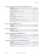
Page 143: ...y MAC2000 Display Overlay O Rings 2066261 015 6 Display Cover Top Display Plastic Parts 1 See Note 2 at the bottom of the table Hardware 3 and Power in Module 2066261 011 Display and O Rings 2066261 014 Display Overlay and O Rings 2066261 015 7 O Ring Display Plastic Parts 1 2066261 007 8 LCD 7 W O Touch AUO Display and O Rings 2066261 014 9 Display Holder AUO Display Plastic Parts 1 2066261 007 2...

Page 144: ...ype of keypad stress or non stress required for your installation For the available stress keypads see Keypads Stress on page 158 For the available non stress keypads see Keypads Non Stress on page 157 2 Keypad FRU Stress and Non Stress is shipped as an assembly of the Keysheet and Display Cover Top assembled together These two parts are shown in the previous illustration as Callouts 4 and 6 respe...

Page 145: ... Cover Top Color Chassis Hardware 2066261 005 15 Push Button Assembly With Pin Cover Top and Plastic Parts 1 2066261 016 Cover Top Color Chassis Hardware 2066261 005 16 Cover Top Deco Cover Top and Plastic Parts 1 2066261 016 Hardware 3 and Power in Module 2066261 011 Display and O Rings 2066261 014 17 O Ring 2 5 Top Assembly Display Overlay and O Rings 2066261 015 Cover Top Color Chassis Hardware...

Page 146: ...Part Number 20 Kiss Pump Assy MAC2000 KISS Pump 2066261 021 21 HRN Kiss Pump MAC2000 Harness Cables 2066261 010 22 Connector Luer Female KISS Pump 2066261 021 23 Nut Lock KISS Pump 2066261 021 24 Plug Luer Male KISS Pump 2066261 021 146 MAC 2000 ECG Analysis System 2053535 003C ...

Page 147: ...6 27 Holder Patient Cable Connector Cover Top and Plastic Parts 1 2066261 016 Cover Top Color Chassis Hardware 2066261 005 28 SCR FH 4 40x1 4 Zinc AHNL DIN965 Hardware 1 2066261 009 29 Base Power Supply Cover Top and Plastic Parts 1 2066261 016 30 Power Supply Power Supply 2066261 012 31 Back Panel Cover Top and Plastic Parts 1 2066261 016 2053535 003C MAC 2000 ECG Analysis System 147 ...

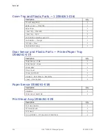
Page 148: ...r Sensor and Plastic Parts Printer Paper Tray 2066261 017 37 Roller Holder Hardware 3 and Power in Module 2066261 011 38 Printer Hinge Rod Hardware 3 and Power in Module 2066261 011 Cover Top Color Chassis Hardware 2066261 005 39 E Clip 4mm dia Hardware 1 2066261 009 Hardware 3 and Power in Module 2066261 011 40 Print Head Print Head Assembly 2066261 019 Hardware 3 and Power in Module 2066261 011 ...

Page 149: ...e 2 Harness Cables 2066261 010 50 Door Switch Assembly Door Sensor and Plastic Parts Printer Paper Tray 2066261 017 51 Cover Door sensor Door Sensor and Plastic Parts Printer Paper Tray 2066261 017 Cover Top Color Chassis Hardware 2066261 005 52 Washer GREIFRING G22x0 6 black Hardware 1 2066261 009 Cover Top Color Chassis Hardware 2066261 005 53 Screw DIN7985 M3x5 4 8 Z A2F ISO7045 Hardware 1 2066...

Page 150: ...066261 004 Cover Top Color Chassis Hardware 2066261 005 61 Screw DIN7985 M3x8 4 8 Z A2F ISO7045 Hardware 1 2066261 009 62 Roller Printer Door 2066261 004 63 Roller Brush Printer Door 2066261 004 64 Gear Wheel Printer Motor and Gears 2066261 003 65 Hinge Printer Door Printer Door 2066261 004 66 Paper Spacer Post Print Printer Door 2066261 004 150 MAC 2000 ECG Analysis System 2053535 003C ...

Page 151: ...Printer Door 2066261 004 Cover Top Color Chassis Hardware 2066261 005 70 Bumpon SJ 6125 15 9MM DIA 6 35MM H Hardware 1 2066261 009 71 Paper Spacer Rear Door Sensor and Plastic Parts Printer Paper Tray 2066261 017 72 Paper Spacer Side Door Sensor and Plastic Parts Printer Paper Tray 2066261 017 Harness Cables 2066261 010 73 Harness PIM TO PS PWA New Hardware 3 and Power in Module 2066261 011 205353...

Page 152: ...nd the parts they include Cover Bottom 2066261 001 Description Qty Cover Bottom MAC2000 1 Damper Assembly 2 Printer 2066261 002 Description Qty Printer Module Assembly 1 Printer Motor and Gears 2066261 003 Description Qty Stepper Motor Assembly 1 Gear Wheel 45 14T 1 Gear Wheel 1 Gear Wheel 1 Printer Door 2066261 004 Description Qty Printer Door 1 Printer Door Hinge 1 Damper Assembly 2 Roller 1 Rol...

Page 153: ...ISO7046 2 E Clip 4 mm Diameter 21 G Clip 2 mm Diameter 3 Bumpon SJ 6125 15 9 mm Diameter 6 35 mm H 4 Cover Top MAC2000 1 Cover Top Deco 1 Push Button Assembly with Pin 1 Push Button Plunger 1 GE Logo New 1 Push Button Spring 1 Main PWA 2066261 006 Description Qty PCB MAC2000 1 Display Plastic Parts 2066261 007 Description Qty O Ring 1 Keyboard Support Part 1 Display Cover Bottom 1 Display Holder A...

Page 154: ...2X6 4 8 Z A2F ISO7045 6 Screw DIN7985 M3X8 4 8 Z A2F ISO7045 7 Screw FH 4 40X1 4 ZINC AHNL DIN965 2 Screw DIN7985 M4X16 4 8 Z A2F ISO7045 4 Screw CSK DIN965 M3X8 4 8 Z AZF ISO7046 2 E Clip 4mm diameter 2 G Clip 2mm diameter 3 Bumpon SJ 6125 15 9MM DIA 6 35MM H 4 Harness Cables 2066261 010 Description Qty Printer Earthing Cable 1 Earthing Cable 1 Harness Printer Cable 1 1 Harness Printer Cable 2 1 ...

Page 155: ...ay Housing Assembly and Cover Top 1 O Ring Display 1 Power Supply 2066261 012 Description Qty Power Supply 1 Battery 2066261 013 Description Qty Battery Pack MAC2000 1 Display and O Rings 2066261 014 Description Qty LCD 7 without Touch AUO 1 O Ring between Display Housing Assembly and Cover Top 1 O Ring Display 1 Display Overlay and O Rings 2066261 015 Description Qty Display Overlay MAC2000 1 O R...

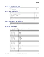
Page 156: ...r and Plastic Parts Printer Paper Tray 2066261 017 Description Qty Paper Spacer Side 1 Paper Spacer Rear 1 Printer Base 1 Motor Cover 1 Printer CAM Shaft 1 Harness Door Sensor Assembly 1 Cover Door Sensor 1 Paper Sensor 2066261 018 Description Qty Cross Bar 1 Paper Sensor Assembly 2 Print Head Assy 2066261 019 Description Qty Print Head Holder 1 ESD Static Brush 3 Print Head 1 Screw DIN7985 M3X4 4...

Page 157: ...1 Keypads Non Stress The following languages are available for non stress keypads Part Number Language 2066261 008 English 2066261 023 German 2066261 024 French 2066261 025 Spanish 2066261 026 Swedish 2066261 027 Italian 2066261 028 Japanese 2066261 029 Dutch 2066261 030 Norwegian 2066261 031 Danish 2066261 032 Czech 2066261 033 Chinese 2066261 034 Hungarian 2066261 035 Polish 2066261 036 Russian ...

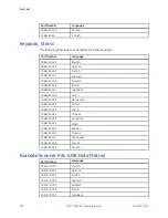
Page 158: ...7 Japanese 2066261 048 Dutch 2066261 049 Norwegian 2066261 050 Danish 2066261 051 Czech 2066261 052 Chinese 2066261 053 Hungarian 2066261 054 Polish 2066261 055 Russian 2066261 056 Slovene 2066261 057 Portuguese 2066261 058 Korean 2066261 059 Finnish Barcode Scanner Kits USB Data Matrix Part Number Language 2035979 001 English 2035979 002 German 2035979 003 French 2035979 004 Spanish 2035979 005 S...

Page 159: ...5M 405535 002 RA BRITSH 10A 250V 2 5M FSD 405535 003 RA ITALIAN 10A 250V 2 5M 405535 004 RA ISRAELI 10A 250V 2 5M 405535 010 RA AUSTRALIAN 10A 250V 2 5M 405535 107 ST SWISS 10A 250V 2 5M 405535 108 RA INDIAN 10A 250V 2 5M 405535 018 ST CHINA RA PLUG 10A 250V 2 5M 405535 011 ST RA PSE 10A 250V 10FT 401855 042 RA BRAZIL 10A 250V 2 5M 401855 901 RA CONT EURO 10A 250V 2 5M EU MFG Software Update SD Ca...

Page 160: ...Parts List 160 MAC 2000 ECG Analysis System 2053535 003C ...

Page 161: ...Title 2053535 002 MAC 2000 ECG Analysis System Operator s Manual 2053535 003 MAC 2000 ECG Analysis System Service Manual 2053535 004 MAC 2000 ECG Analysis System Supplies and Accessories Reference Guide 2053535 065 MAC 2000 ECG Analysis System Quick Reference Guide 2036070 006 Marquette 12SL ECG Analysis Program Physician s Guide 2025762 163 GE Cardiology Open XML Reference Manual 2020299 025 LAN ...

Page 162: ...2053535 014 German 2053535 015 Greek 2053535 016 Hungarian 2053535 017 Indonesian 2053535 018 Italian 2053535 019 Japanese 2053535 020 Korean 2053535 021 Latvian 2053535 022 Lithuanian 2053535 023 Norwegian 2053535 024 Polish 2053535 025 Portuguese Brazilian 2053535 026 Portuguese European 2053535 027 Romanian 2053535 028 Russian 2053535 029 Serbian 2053535 030 Slovakian 2053535 031 Spanish 205353...

Page 163: ...35 037 Croatian 2053535 038 Czechoslovakian 2053535 039 Danish 2053535 040 Dutch 2053535 004 English 2053535 041 Estonian 2053535 042 Finnish 2053535 043 French 2053535 044 German 2053535 045 Greek 2053535 046 Hungarian 2053535 047 Indonesian 2053535 048 Italian 2053535 049 Japanese 2053535 050 Korean 2053535 051 Latvian 2053535 052 Lithuanian 2053535 053 Norwegian 2053535 054 Polish 2053535 055 P...

Page 164: ...uments MAC 2000 ECG Analysis System Supplies and Accessories Reference Guides cont d Part Number Language 2053535 062 Swedish 2053535 063 Turkish 2053535 064 Ukranian 164 MAC 2000 ECG Analysis System 2053535 003C ...

Page 165: ...stem may cause unexpected or adverse operation Do not use portable phones or other electronic equipment that may emit radio frequency RF near this system WARNING EQUIPMENT MALFUNCTION Do not use the equipment or system adjacent to or stacked with other equipment If adjacent or stacked use is necessary test the equipment or system to verify normal operation in the configuration in which you are usi...

Page 166: ... to cause any interference in nearby electronic equipment Class B equipment is suitable for use in all establishments including domestic establishments and those directly connected to the public low voltage power supply network that supplies buildings used for domestic purposes Harmonic emissions 2nd 40th Harmonic IEC 60601 1 2 2007 IEC 61000 3 2 2005 Class A Voltage fluctuations Flicker emissions...

Page 167: ...ply input lines 5 Ut 95 dip in Ut for 0 5 cycles 40 Ut 60 dip in Ut for 5 cycles 70 Ut 30 dip in Ut for 25 cycles 5 Ut 95 dip in Ut for 5 s Mains power should be that of a typical commercial or hospital environment If the user requires continued system operation during power mains interruptions it is recommended that the system is powered from an applicably rated uninterruptible power supply or a ...

Page 168: ...f the system including the cables than the recommended separation distance calculated for the equation applicable to the frequency of the transmitter Conducted RF 3 Vrms 150 KHz to 80 MHz 2 Hz mod Multilink Lead set 3 0 Vrms Value Lead set 3 0 Vrms KISS Lead set 0 3 Vrms Recommended separation distance Multilink Lead Set d 1 2 P Value Lead Set d 1 2 P KISS Lead Set d 11 6 P 168 MAC 2000 ECG Analys...

Page 169: ... marked with the following symbol NOTE At 80 MHz and 800 MHz the higher frequency range applies These guidelines may not apply in all situations Electromagnetic propagation is affected by the reflection from structures objects and people aField strengths from fixed transmitters such as base stations for radio cellular cordless telephones and land mobile radio AM and FM radio broadcast and TV broad...

Page 170: ...er of transmitter in watts W 150 kHz to 80 MHz d meters 3 5 V1 x P d meters for V1 3 Vrms 80 MHz to 800 MHz d 3 5 E1 x P d for E1 3 V m 800 MHz to 2 5 GHz d 7 E1 x P d for E1 3 V m meters feet meters feet meters feet 0 01 0 117 0 383 0 117 0 383 0 233 0 766 0 1 0 369 1 210 0 369 1 210 0 738 2 421 1 1 167 3 828 1 167 3 828 2 333 7 655 10 3 689 12 104 3 689 12 104 7 379 24 208 100 11 667 38 276 11 6...

Page 171: ...mainboard Environmental Conditions Item Operating Specifications Transport Storage Specifications Temperature 10 C to 40 C 50 F to 104 F 40 C to 70 C 40 F to 158 F Relative humidity 20 to 95 RH non condensing 15 to 95 RH non condensing Pressure 700 hPa to 1060 hPa Altitude range 3010 9m to 381 9m 9878 28 ft to 1252 95 ft 500 hPa to 1060 hPa Altitude range 5570m to 380m 18274 28 ft to 1246 72 ft Di...

Page 172: ...er resistant and meet MDM4021 Cleaning and Chemical Resistance Performance Guidelines Functions Standard Stress Printer Item Specifications Technology Integrated thermal dot array Paper Speed 5 12 5 mm s at 10 accuracy 25 50 mm s at 2 accuracy Printer motor speed Report printing within 25 seconds Number of traces Up to 12 ECG traces sampled at 500 or 1000 Hz Sensitivity gain 2 5 5 10 20 40 mm mV w...

Page 173: ...ithout printing minimum Charge time Approximately 3 5 hours from total discharge with device off Acquisition Processing and Performance LEDs Item Specifications Battery charging Steady amber Battery charging Flashing amber battery low Off battery fully charged when connected to AC Mains neither charging nor low when running on battery External power Steady green external power connected Off no ext...

Page 174: ...0 or 1000 samples second channel Digital sampling rate 16000 samples second channel for normal data acquisition Pace sample rate 75K samples second channel ECG on screen preview On screen preview of acquired 10 second ECG waveform Acquisition mode Pre acquisition or post acquisition provides 10 seconds of instantaneous ECG acquisition Resolution 4 88 µV LSB Frequency range 0 04 to 150 Hz Low cutof...

Page 175: ...amplitude Archiving ECG data is printed out Internal memory is present on this system External Storage SD Card available for storage Input Output Interface RS232 port for connectivity to MUSE systems v7 1 1 and v8 0 1 and CASE CardioSoft systems V6 51 V6 61 and CardioSoft V6 71 and remote control signal from ergometers Ethernet interface RJ45 connector Channels 6 12 QRS detection Available Muscle ...

Page 176: ...nsumables Electrodes leadwires cables and so forth For a complete list of all available supplies and accessories for this system refer to the MAC 2000 Supplies and Accessories Reference Guide Barcode Scanner Use to enter patient information from a patient barcode Secure Digital High Capacity SDHC Card 4 GB Product Options For a complete list of product options and codes refer to Options Setup in t...

Page 177: ...r use in a medical environment It is sorted by region and within region by country When setting up WiFi communications in your device select the channel that is allowed in your country of operation Region Country Allowed Channel s Africa South Africa 13 Argentina 13 Brazil 11 Canada 11 Chile 11 Mexico 11 Panama 11 Americas U8A 11 China 13 India 13 Indonesia 13 Japan 1 13 b g 14 b Korea 13 Kuwait 1...

Page 178: ...any 13 Greece 13 Hungary 13 Iceland 13 Ireland 13 Italy 13 Latvia 13 Liechtenstein 13 Lithuania 13 Luxembourg 13 Malta 13 Netherlands 13 Norway 13 Poland 13 Portugal 13 Romania 13 Russia 13 Slovakia 13 Slovenia 13 Spain 13 Sweden 13 Switzerland 13 Turkey 13 Europe UK 13 Australia 13 Oceania New Zealand 13 178 MAC 2000 ECG Analysis System 2053535 003C ...

Page 179: ...FT EMC immunity test 167 electromagnetic separation distances 170 electromagnetic compatibility 165 electrostatic discharge ESD EMC immunity test 167 EMC 18 floor composition 167 mains power 167 separation distances 170 EMC compatibility 165 EMC emissions test flicker emissions 166 harmonic emissions 166 RF emissions conducted 166 radiated 166 voltage fluctuation 166 EMC immunity test conducted RF...

Page 180: ... 38 escape 38 function 38 lead 37 on off 37 option 38 power on 37 rhythm 37 shift 38 space bar 38 writer stop 37 L lead key 37 LED description external power 173 LED descriptions battery charging 173 M manufacturer responsibilities 20 medians stress key 39 medical device classification 17 N Notes conventions 32 O OEM 2 on off key 37 option key 38 Original Equipment Manufacturer OEM 2 P packaging s...

Page 181: ...35 space bar 38 speed load down key 39 speed load up key 39 standard keypad 37 start treadmill key 39 stop treadmill key 39 stress keypad 39 stress keys 12ld 39 comment 39 enter BP 39 exercise 39 grade down 39 grade up 39 hold stage 39 median 39 pretest 39 recall 39 recovery 39 speed load down 39 speed load up 39 start treadmill 39 stop treadmill 39 test end 39 symbols device 21 packaging 21 syste...

Page 182: ...182 MAC 2000 ECG Analysis System 2053535 003C ...

Page 183: ......

Page 184: ...GmbH Munzinger Straße 5 D 79111 Freiburg Germany Tel 49 761 45 43 0 Fax 49 761 45 43 233 GE Medical Systems Information Technologies Inc Asia GE China Co Ltd 1 Huatuo Road Zhangjiang Hi tech Park Pudong Shanghai People s Republic of China 201203 Tel 86 21 3877 7888 Fax 86 21 3877 7451 GE Medical Systems Information Technologies Inc a General Electric Company going to market as GE Healthcare www ge...

Reviews: