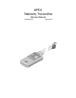
background image

APEX

Telemetry Transmitter

Service Manual

401566-166

 Revision D

Summary of Contents for Marquette 418793-001

Page 1: ...APEX Telemetry Transmitter Service Manual 401566 166 Revision D ...

Page 2: ...SCRIPT OnlineABG OXYMONITOR Pres R Cuff PRESSURE SCRIBE QMI QS Quantitative Medicine Quantitative Sentinel RAC RAMS RSVP SAM SEER SILVERTRACE SOLAR SOLARVIEW Spectra 400 Spectra Overview Spectra Tel ST GUARD TRAM TRAM NET TRAM RAC TRAMSCOPE TRIM KNOB Trimline UNION STATION UNITY logo UNITY NETWORK Vari X Vari X Cardiomatic VariCath VARIDEX VAS and Vision Care Filter are trademarks of GE Marquette ...

Page 3: ...ation 1 5 Service Requirements 1 5 Equipment Identification 1 5 Warranty 1 5 How to Reach Us 1 6 Customer Support and Equipment Repair Information 1 6 Ordering Service Parts 1 6 Supplies Information 1 6 2 EQUIPMENT OVERVIEW 2 1 Overview 2 2 Features 2 2 Battery Compartment 2 2 Indicators 2 3 Interface Port 2 3 Transmitter Versions 2 3 APEX Oximeter Accessory 2 4 Interconnection 2 4 Battery Compart...

Page 4: ... 8 RF Test 3 9 Setup 3 9 Sideband Balance 3 10 Carrier Suppression 3 10 Carrier Frequency Error 3 11 Power Output 3 11 RF Signal Integrity 3 11 Communications Tests 3 12 Lead s Fail 3 12 Verify Graph Request 3 12 Pause Alarm 3 13 Pacemaker Transmission 3 13 ECG Waveform Transmission 3 13 Change Battery Message 3 14 Completion 3 14 Oximeter Operational Tests 3 14 Completion 3 15 Accutracker DX NIBP...

Page 5: ...requent Lead Fail Events 4 3 Short Battery Life 4 3 Oximeter 4 4 Check Probe Message 4 4 Low Quality Signal 4 4 Probe Off 4 4 Short Battery Life 4 4 No SpO2 Data 4 5 The Saturation Value is x 4 5 Powerup Selftests 4 6 Transmitter 4 6 Oximeter 4 7 Accutracker 4 7 Power Shutdown During Leads Fail 4 8 Transmitter 4 8 5 CALIBRATION 5 1 Programming the Transmitter for Use 5 2 Procedure 5 2 Completion 5...

Page 6: ...r 6 10 Power Supplies 6 10 Exploded View PN 418793 001A 002A 003A 004A 6 11 Block Diagram PN 418793 001A 002A 003A 004A 6 14 Parts List PN 418793 001A 002A 003A 004A 6 15 7 TRANSMITTER PCB 7 1 General 7 2 Versions of the Circuit Board 7 2 Connectors 7 2 Switches Controls and Adjustments 7 2 Parts Location Diagram PN 801278 001A 003A 7 3 Parts List PN 801278 001A 003A 7 6 Parts Location Diagram PN ...

Page 7: ... Oximetry 8 3 Packaged Parts List 420364 001A 421049 002A 8 5 Upper Level Parts List 420364 001A 8 6 Exploded View 420364 001A 8 7 Upper Level Parts List 421049 002A 8 8 Exploded View 421049 002A 8 9 Interconnection Diagram 421049 001A 002A 8 10 PCB Parts List 421191 001A 8 11 Parts Location Diagram 421191 001A 8 13 PCB Schematic Diagram PN 2456 000A 8 16 ...

Page 8: ...CONTENTS vi APEX Telemetry Transmitter Revision D 401566 166 ...

Page 9: ...Information 1 3 Responsibility of the Manufacturer 1 3 Intended Use 1 3 Equipment Symbols 1 4 Warnings Cautions and Notes 1 4 Service Information 1 5 Service Requirements 1 5 Equipment Identification 1 5 Warranty 1 5 How to Reach Us 1 6 Customer Support and Equipment Repair Information 1 6 Ordering Service Parts 1 6 Supplies Information 1 6 ...

Page 10: ...ted to have a background in electronics including analog and digital circuitry with RF and microprocessor architectures This manual does not include extensive information on the circuit boards that comprise the transmitter assembly These assemblies are not field repairable and require return to a GE Marquette service facility for any repairs Revision History Revision Date Comment A 26 August 1997 ...

Page 11: ... or on the order of a physician Contact GE Marquette Medical Systems for information before connecting any devices to the equipment that are not recommended in this manual Parts and accessories used must meet the requirements of the applicable IEC 601 series safety standards and or the system configuration must meet the requirements of the IEC 60601 1 1 medical electrical systems standard Periodic...

Page 12: ...zard is defined as a source of potential injury to a person WARNING indicates a potential hazard or unsafe practice which if not avoided could result in death or serious injury CAUTION indicates a potential hazard or unsafe practice which if not avoided could result in minor personal injury or product property damage NOTE provides application tips or other useful information to assure that you get...

Page 13: ...spective of usage is essential to ensure that the equipment will always be functional when required Equipment Identification Every GE Marquette Medical Systems device has a unique serial number for identification The serial number appears on the product label on the base of each unit Warranty 1 year Month Manufactured A January B February C March D April E May F June G July H August J September K ...

Page 14: ...m is unobtainable the following will be necessary to order the item model and serial number of the equipment part number name of the assembly where the item is used item name and where applicable reference designation e g R13 S12 U32 Supplies Information Supply items are generally those items used during normal operation of a product Leadwires electrodes patient cables printer paper Aqua Knot wate...

Page 15: ...VIEW CONTENTS Overview 2 2 Features 2 2 Battery Compartment 2 2 Indicators 2 3 Interface Port 2 3 Transmitter Versions 2 3 APEX Oximeter Accessory 2 4 Interconnection 2 4 Battery Compartment 2 4 Indicators 2 5 Technical Specifications 2 6 Underwriters Laboratory Inc 2 7 ...

Page 16: ...or III Leads I II III V aVR aVL and aVF are the possible lead selections for the five wire leadwire set connected to the APEX S transmitter The following figure locates many of the transmitter s user interface components Descriptions of each item follows Battery Compartment The battery compartment cover is located on the bottom of the transmitter Once the cover has been opened two AA alkaline batt...

Page 17: ...s are illuminated if the associated lead signal is good PAUSE ALARMS LED Pressing both the VERIFY LEADS and the GRAPH controls simultaneously results in an alarm pause condition in which the alarms are disabled and the PAUSE ALARMS LED starts flashing This condition lasts for 5 minutes When the PAUSE ALARMS LED stops flashing the condition is over To end the pause alarms condition prematurely both...

Page 18: ... oximeter 2 Connect the supplied interconnection cable to the APEX oximeter 5 pin connector labeled INT interface 3 Connect the other end of the supplied interconnection cable to APEX S transmitter 5 pin connector labeled INT interface NOTE You must connect the APEX Oximeter to a transmitter labeled APEX S The APEX Oximeter does not function with transmitters labelled APEX 3 or APEX 5 Battery Comp...

Page 19: ...h is indicated by the flashing power LED in the upper left corner of the display DISPLAY ON OFF This button has the following functions Press the DISPLAY ON OFF button to turn the display ON for one minute To turn the display on continuously press and hold the DISPLAY ON OFF button for two seconds The POWER LED on the digital display will turn OFF to indicate continuous mode To turn the display OF...

Page 20: ...dity 5 to 95 noncondensing Storage Relative Humidity 5 to 95 noncondensing Water Immersion Water resistant Battery Specifications Item Description Type ANSI NEDA 15A 1 5V AA alkaline 2 required Life 60 hours typical Transmission Specifications Item Description Frequency Range For 001 units 174 050 to 215 950 MHz US TV channels 7 to 13 For 002 units 216 000 to 242 000 MHz For 003 units 173 30 173 7...

Page 21: ...r minute Displays Patient Indicator PERFUSION LED Digital Display 3 digit 7 segment LEDs Measurement Wavelengths Red 660 Nanometers Infrared 910 Nanometers SpO2 Accuracy 1 S D 70 100 3 of full scale Below 70 not specified Standard Deviation S D is a statistical measure up to 32 of the readings may fall outside these limits Rate Accuracy 3 1 digit Temperature Operating 20 to 50 C Non Operating 30 t...

Page 22: ...EQUIPMENT OVERVIEW Technical Specifications 2 8 APEX Telemetry Transmitter Revision D 401566 166 For your notes ...

Page 23: ...8 RF Test 3 9 Setup 3 9 Sideband Balance 3 10 Carrier Suppression 3 10 Carrier Frequency Error 3 11 Power Output 3 11 RF Signal Integrity 3 11 Communications Tests 3 12 Lead s Fail 3 12 Verify Graph Request 3 12 Pause Alarm 3 13 Pacemaker Transmission 3 13 ECG Waveform Transmission 3 13 Change Battery Message 3 14 Completion 3 14 Oximeter Operational Tests 3 14 Completion 3 15 Accutracker DX NIBP ...

Page 24: ...hese solutions may shorten the transmitter s useful lifetime after repeated applications Remove the batteries before cleaning the transmitter Disconnect the leadwires from the transmitter Always dilute the cleaning solutions according to the manufacturer s recommendations Always wipe off the cleaning solutions with a clean dry lint free cloth after cleaning Never pour or spray water or any cleanin...

Page 25: ...ransmitter and leadwires should be inspected for damage before they are used on any new patients This inspection is vital to maintain the integrity of the transmitter s environmental seals upon receipt of the unit every twelve months thereafter each time a circuit board is removed or replaced and record the results on the Preventive Maintenance Inspection Form included at the end of this chapter C...

Page 26: ...ect the leadwires for cracks or other damage Replace leadwires that are cracked damaged or no longer flexible Remove the battery cover and inspect the battery contacts Clean them if they are dirty or corroded If there are any visible signs of moisture within the battery compartment inspect the other seals in the case Do not use a transmitter with leaking seals If the transmitter or leadwires fails...

Page 27: ...avoid damage to the transmitter follow these guidelines Remove the batteries before cleaning the transmitter Disconnect the leadwires from the transmitter Always dilute the cleaning solutions according to the manufacturer s recommendations Always wipe off the cleaning solutions with a clean dry lint free cloth after cleaning Never use a cleaning substance that contains wax or wax compounds Never p...

Page 28: ...Displays This test verifies LED operation 1 Attach the leadwires to an ECG source 2 Install batteries into the transmitter then wait for the powerup selftests to be completed 3 Press the VERIFY LEADS and GRAPH buttons simultaneously The LEAD STATUS and CHANGE BATTERY LEDs should flash twice to acknowledge the switch was pressed Then the PAUSE ALARM LED should start flashing Powerup Selftests This ...

Page 29: ... transmitter being tested at the central station This test could also be done using the RF monitor to measure the decrease in RF output under a LEADS FAIL condition Change Battery LED This test verifies that the transmitter does indicate a low battery condition if the battery voltage drops below 1 90V 04V 1 Remove batteries from transmitter 2 Connect the low voltage power supply to the APEX RF tes...

Page 30: ...g page to measure current flow 5 Reconnect the APEX RF test cable to the transmitter 6 Quickly measure the current flow into the transmitter NOTE In an all leads fail condition that lasts for longer than 6 seconds the transmitter reduces its power output When the APEX RF test cable is connected the transmitter goes into an all leads fail condition Therefore you have only six seconds to measure the...

Page 31: ...F test cable should be prepared as shown in the following diagram Configure the RF monitor as follows 1 Program the frequency of the transmitter being tested 2 For the 2nd function meter a Set the FREQ ERROR to 1K b Set the Mode to REC c Set Modulation to FM MID d Set the METER to 20 kHz e Set the HORIZONTAL to 5 kHz DIV 3 Allow the RF monitor to operate for at least 15 minutes for temperature sta...

Page 32: ...red They should be within 1 dB of each other as shown in the figure below Carrier Suppression This test verifies that the carrier level is below the two main sideband lobes 1 If continuing from the previous test step the transmitter is functioning in the correct mode Proceed to step 2 Otherwise while holding the VERIFY LEADS button down install batteries in the transmitter This starts the transmit...

Page 33: ...e VERIFY button while installing the batteries This starts the transmitter in the square wave mode 3 Once the test has been started shorting pins one and two on the interface port connector causes the test to be repeated until the short is removed 4 Using the RF monitor verify the peak output to be greater than 45 dBm RF Signal Integrity This test verifies the RF output of the transmitter 1 At the...

Page 34: ...eriod 5 Verify by repeating several times each time with a different lead wire removed from the ECG source The LED associated with the disconnected leadwire should not remain illuminated NOTE In 3 lead mode the reference lead is displayed as Good during the VERIFY LEADS test The V lead LED does not illuminate 6 Configure the central station to monitor the test transmitter Repeat the previous steps...

Page 35: ...ly Once the PAUSE ALARMS LED begins flashing press the VERIFY LEADS and GRAPH buttons again The PAUSE ALARMS LED should cease flashing Pacemaker Transmission This test verifies detection of a pace pulse and transmission to the central station display 1 Connect an ECG simulator to the transmitter 2 With the transmitter operating and ECG waveforms from the transmitter being displayed on the central ...

Page 36: ... p n 408610 001 Nonin simulator cable adapter p n 420970 001 1 Record the unit s serial number 2 Connect the oximeter to the Apex S transmitter 3 Admit the transmitter to a V6 CDT LAN system Make sure that the SpO2 parameter box comes up on the Central display and contains information matching the oximeter s display If the unit fails discontinue the test Return or repair the unit after double chec...

Page 37: ...rquette Medical Systems Service and Supplies See How to Reach Us in Chapter 1 Accutracker Display The following displays on the Accutracker when you turn it on press and hold the button while turning the switch on This display includes hardware and software version the Gain Setting for the mic and the pressure setting mmHg Pressure Calibration Check Do the following to ensure the functionality of ...

Page 38: ...ICE SELF TEST displays immediately press the button to discontinue the reading in progress This step is necessary to identify that a reading can be aborted if necessary during a test in case there is a problem i e the cuff slips down the arm an electrode becomes detached etc 8 Turn the Accutracker off to exit this mode Over Pressure Release Check The Over Pressure release should occur whenever a p...

Page 39: ...or the pressure in mmHg displayed on the Accutracker LCD The Accutracker should leak no more than 2mmHg per minute Communication Test This procedure verifies that the telemetry system transmits and receives the data correctly from the Accutracker 1 Attach the Accutracker to the APEX Telemetry system NOTE You must have ECG leads with a shorting cable or simulator attached to the APEX Telemetry syst...

Page 40: ...ith this manual For the latest PM form regarding this product contact GE Marquette Service If repairs adjustments are made or you replace any parts describe this in the area provided on the PM form Include any comments regarding any unusual environmental conditions that may affect the operation or reliability of the equipment in the area provided on the PM form On the following pages a repair log ...

Page 41: ...MAINTENANCE Repair Log Revision D APEX Telemetry Transmitter 3 19 401566 166 Repair Log Institution Name Unit Name Date TTX Maintenance Repair Technician ...

Page 42: ...MAINTENANCE Repair Log 3 20 APEX Telemetry Transmitter Revision D 401566 166 Institution Name Unit Name Date TTX Maintenance Repair Technician ...

Page 43: ...age 4 2 Before Calling for Service 4 3 Transmitter 4 3 Frequent Lead Fail Events 4 3 Short Battery Life 4 3 Oximeter 4 4 Check Probe Message 4 4 Low Quality Signal 4 4 Probe Off 4 4 Short Battery Life 4 4 No SpO2 Data 4 5 The Saturation Value is x 4 5 Powerup Selftests 4 6 Transmitter 4 6 Oximeter 4 7 Accutracker 4 7 Power Shutdown During Leads Fail 4 8 Transmitter 4 8 ...

Page 44: ...components are being serviced the components are exposed to several sources of static electricity ranging from human hands to improperly grounded test equipment For this reason it is recommended that all service workstations be as static free as possible Reducing ESD Damage The following guidelines can help make your workstation more resistant to the damage that can be caused by static electricity...

Page 45: ...tall a fresh set of alkaline AA batteries into the transmitter and then verify battery life Once used in a transmitter for any length of time used batteries should be disposed of recycled immediately Batteries must not be re used Batteries should be used for only one patient Do not store used batteries for use with the next patient A battery contains a finite amount of stored energy Each unit of t...

Page 46: ...or any length of time used batteries should be disposed of recycled immediately Batteries must not be re used Batteries should be used for only one patient Do not store used batteries for use with the next patient A battery contains a finite amount of stored energy Each unit of time a battery is used diminishes the amount of stored energy Installing a used battery in an oximeter results in a great...

Page 47: ...mitter If the APEX Oximeter is still connected but the receiver receives no valid data check to see if the patient is within antenna range transmitter dropout The Saturation Value is x If the APEX Oximeter is still connected but the receiver receives no valid data check to see if the patient is within antenna range transmitter dropout Check to see if the oximeter is connected to the APEX S transmi...

Page 48: ...g the transmitter The follows tests are performed at powerup of the transmitter 1 First a RAM test is performed Either the RAM in the transmitter s microprocessor circuit passes or fails this test If the RAM passes the testing continues If the RAM fails the test all LEDs on the transmitter are flashed five times The RAM test is repeated and continues in a loop as long as the test fails and power i...

Page 49: ...uously during normal operation If an error is detected the transmitter resets itself Oximeter The following is the APEX Oximeter powerup sequence 1 The display reads 888 888 and the perfusion LED is red for approximately one second 2 The display reads 888 888 and the perfusion LED is green for approximately one second 3 The software revision level is displayed for 1 2 seconds and the perfusion LED...

Page 50: ...f all leads fail for more than about six seconds the microprocessor shuts off power supplied to the RF modulator circuitry This reduces the battery discharge rate when no data actually transmits Once the leads are reconnected about one second is required for the microprocessor to power up the modulator circuitry and resume transmitting patient data ...

Page 51: ...Revision D APEX Telemetry Transmitter 5 1 401566 166 5 CALIBRATION CONTENTS Programming the Transmitter for Use 5 2 Procedure 5 2 Completion 5 3 Accutracker Calibration 5 4 ...

Page 52: ... do the following 1 Remove the leadwire set Remove the plug from the interface port of the transmitter Connect the APEX Programming Device to the programming port 2 Connect the Programming Device to the PC using the provided serial cable Note which COM port the cable is connected to on the PC Information about changing the COM port selection is available in the help display enter or H 3 From DOS r...

Page 53: ...ting range of the transmitter The complete frequency range for each transmitter is printed inside the battery compartment If the transmitter is set correctly and the lock error message persists the unit requires factory servicing Completion 1 Disconnect the Programming Device and the interface cable 2 Replace the plug into the interface port of the transmitter 3 Install a new TTX number label with...

Page 54: ...er Calibration It is recommended that you follow the Accutracker DX NIBP Operational Tests in Chapter 3 Maintenance when you receive the Accutracker and every 12 months thereafter If the unit fails return the unit to GE Marquette Medical Systems Service and Supplies See How to Reach Us in Chapter 1 ...

Page 55: ... 6 5 Second Amplifier Stage 6 5 Third Amplifier Stage 6 5 Pace Detect 6 5 Digital Circuitry 6 6 Modulator Drive and Filter Circuit 6 7 RF Section 6 7 Phase Locked Loop 6 8 Frequency Doubler 6 9 Frequency Modulator 6 10 Output Amplifier 6 10 Power Supplies 6 10 Exploded View PN 418793 001A 002A 003A 004A 6 11 Block Diagram PN 418793 001A 002A 003A 004A 6 14 Parts List PN 418793 001A 002A 003A 004A ...

Page 56: ...mitter Four versions of the transmitter PCB are presented in the next chapter Upper Level Part Number Frequency Type Frequency Range PCB Part Number Schematic Part Number 418793 001 VHF for U S 174 05 to 215 95 MHz 801278 001 SD801278 001 418793 002 VHF international 216 00 to 242 00 MHz 801278 002 SD801278 002 418793 003 VHF for U K 173 30 173 75 173 85 173 95 MHz 801278 003 SD801278 001 418793 0...

Page 57: ...nstalled into its battery compartment Patient data is transmitted until the batteries are removed or are depleted Two switches are provided on the front of the transmitter for requesting a central station data graph verifying lead status and for de activating the visual and audible alarms at the central station unit There are no other user accessible features on the transmitter The transmitter PCB...

Page 58: ...UPPER LEVEL ASSEMBLY Theory of Operation 6 4 APEX Telemetry Transmitter Revision D 401566 166 The following block diagram provides a more detailed analysis of the three general sections of circuitry ...

Page 59: ...U108 The crosspoint switch is controlled by microprocessor U5 and is configured based on the current lead fail status Third Amplifier Stage The final ECG stage sheet 4 has slew limiting circuitry of 1 0 V sec RTI referred to input U112 U114 2 40 Hz high pass AC coupling filter a 40 Hz low pass filter U110 U115 and a gain of 101 Total ECG gain through the ECG circuits is 250 so that a maximum input...

Page 60: ...rt B I O pins The 7 bit digital value is converted to an analog voltage by an external resistor divider network that is connected to the inputs of the 10 bit A D converter U100 through a unity gain buffer amplifier U108 Digital Circuitry The digital circuitry consists of microprocessor U5 sheet 8 EEPROM U103 watchdog timer U102 and A D converter U100 The microprocessor is clocked with a 2 4576 MHz...

Page 61: ... signals Modulator Drive and Filter Circuit The modulator drive circuit U111 on sheet 9 provides the mixer of the frequency modulator with adequate drive and provides an 8 pole linear phase filter to reduce sideband harmonics and assures a constant phase delay in the 6 12kHz bandpass RF Section The RF section of the transmitter generates a carrier frequency which is phase modulated by the digital ...

Page 62: ...rrier frequency Any error in phase or frequency between the reference signal and the sampled RF signal is converted to an error signal at the D0 port of the PLL pin 6 This error signal is filtered by a loop filter and used as a tuning voltage for the VCO PLL U2 clock data and enable inputs pins 11 13 and 14 are used to program the frequency synthesizer to one half the desired carrier frequency In ...

Page 63: ...3 and L24 for 004 impedance match the output impedance of Q3 to the input impedance of the R37 R52 R53 circuit 50Ω for maximum power transfer Frequency Doubler The frequency doubler section doubles the frequency of its input i e the output signal from the VCO Transistor amplifier Q4 operates nonlinearly to increase the level of the VCO harmonics generated in the amplifier The amplifier output is t...

Page 64: ...Output Amplifier The output amplifier section amplifies the phase modulated carrier signal and isolates the frequency modulator section from the antenna A transistor amplifier is formed using Q2 and is coupled to the antenna by matching elements at the output of Q2 The input to the amplifier is filtered using C1 C2 C3 C7 C8 L2 and L4 for 001 002 003 and C3 C7 C8 L4 and L19 for 004 This attenuates ...

Page 65: ...UPPER LEVEL ASSEMBLY Exploded View PN 418793 001A 002A 003A 004A Revision D APEX Telemetry Transmitter 6 11 401566 166 Exploded View PN 418793 001A 002A 003A 004A Sheet 1 of 3 ...

Page 66: ...UPPER LEVEL ASSEMBLY Exploded View PN 418793 001A 002A 003A 004A 6 12 APEX Telemetry Transmitter Revision D 401566 166 Sheet 2 of 3 ...

Page 67: ...UPPER LEVEL ASSEMBLY Exploded View PN 418793 001A 002A 003A 004A Revision D APEX Telemetry Transmitter 6 13 401566 166 Sheet 3 of 3 ...

Page 68: ...UPPER LEVEL ASSEMBLY Block Diagram PN 418793 001A 002A 003A 004A 6 14 APEX Telemetry Transmitter Revision D 401566 166 Block Diagram PN 418793 001A 002A 003A 004A ...

Page 69: ...015 2 16 Screw PNH 2 56 x 1 4 4760 016 2 17 Screw PNH 2 56 x 3 8 4760 017 1 18 O Ring Transmitter 415164 001 1 19 O Ring Interface Socket 411916 001 1 20 Label Serial Number 404525 001 2 22 Box Transmitter 411739 001 1 23 Insert Film Box 411739 002 1 26 Washer Foam 415079 001 4 28 Case Transmitter w Switch Membrane English AHA Determined by Destination 416712 001 1 Case Transmitter w Switch Membra...

Page 70: ...Label 174 05 215 95 MHz For PN 418793 001 Only 416050 001 1 Frequency Label 261 00 242 00 MHz For PN 418793 002 Only 416050 002 1 Frequency Label 173 30 173 95 MHz For PN 418793 003 Only 416050 003 1 Frequency Label 430 00 474 00 MHz For PN 418793 004 Only 416050 004 1 35 Instruction Sheet Transmitter Programming 401566 090 1 36 Instruction Sheet Transmitter Return Repair 401566 089 1 37 Label Mod...

Page 71: ...Adjustments 7 2 Parts Location Diagram PN 801278 001A 003A 7 3 Parts List PN 801278 001A 003A 7 6 Parts Location Diagram PN 801278 002A 7 10 Parts List PN 801278 002A 7 13 Parts Location Diagram PN 801278 004A 7 17 Parts List PN 801278 004A 7 20 Schematic Diagram PN SD801278 001A 7 24 Schematic Diagram PN SD801278 002A 7 37 Schematic Diagram PN SD801278 004A 7 38 ...

Page 72: ...ernational Tuning parts values parts location and page six of the schematic diagram are different 801278 003 SD801278 001 VHF for U K Parts list parts location and schematic diagram are the same as 001 except L5 is tuned to a different frequency 801278 004 SD801278 004 UHF international Tuning parts values parts location and page six of the schematic diagram are different Pin Signal Name I O Type ...

Page 73: ...TRANSMITTER PCB Parts Location Diagram PN 801278 001A 003A Revision D APEX Telemetry Transmitter 7 3 401566 166 Parts Location Diagram PN 801278 001A 003A Sheet 1 of 3 ...

Page 74: ...TRANSMITTER PCB Parts Location Diagram PN 801278 001A 003A 7 4 APEX Telemetry Transmitter Revision D 401566 166 Sheet 2 of 3 ...

Page 75: ...TRANSMITTER PCB Parts Location Diagram PN 801278 001A 003A Revision D APEX Telemetry Transmitter 7 5 401566 166 Sheet 3 of 3 ...

Page 76: ...ap NPO 22pF 5 50V SM 411576 002 6 C35 149 162 163 165 Cap NPO 68pF 5 50V SM 411576 005 5 C36 43 55 Cap NPO 47pF 5 50V SM 411576 008 3 C37 Cap NPO 5 6pF 0 25pF 411576 017 1 C38 39 Cap NPO 4 7pF 0 25pF 411576 011 2 C44 45 120 121 150 Cap Tant 10µF 10 6 3V 411588 003 5 C46 47 Cap Tant 220µF 20 10V SM 412662 002 2 C48 49 50 Cap Tant 330µF 20 6 3V 412662 001 3 C52 54 100 102 104 106 108 111 116 118 133...

Page 77: ... 471nH 14 Turns SM 414076 001 1 L15 17 Inductor 33µH 1 3A 411522 002 2 L16 18 Inductor 1000nH SM 404738 005 2 Q1 Transistor PNP SM BC808W 411607 001 1 Q2 4 Transistor NPN SM AT 32011 418605 001 2 Q3 Transistor NPN RF SM 5031 2715 031 1 Q100 Transmitter NPN SM BC850W 411606 001 1 R1 22 37 52 53 109 Res Cer 49 9 Ω 1 1 16W SM 410334 040 6 R2 15 46 47 50 107 108 110 119 120 124 125 131 132 135 136 138...

Page 78: ...60 Res Cer 16 9K 1 1 16W SM 410334 039 2 R161 162 Res Cer 80 6K 1 1 1 6W SM 410334 038 2 R165 175 198 Res Cer 1 62K 1 1 16W SM 410334 029 3 R168 Res Cer 4 99K 1 1 16W SM 410334 066 1 R169 Res Cer 1K 1 1 16W SM 410334 008 1 R183 184 Res Cer 18 2K 1 1 16W SM 410334 001 2 R185 194 Res Cer 23 2K 1 1 16W SM 410334 069 2 R201 Res Cer 3 01K 1 1 16W SM 410334 018 1 R204 Res Cer 402K 1 1 1 6W SM 410334 138...

Page 79: ...ration Ampl Quad SM TLV2334 411530 001 1 U114 Operation Ampl Quad SM LMC6484 411570 001 1 U116 Microcontroller APEX Pace Enhancement V1A 419292 001 1 Y1 Crystal 10 000 MHz SM 417030 001 1 Y2 Crystal 2 4576 MHz 403780 001 1 Tape Foam Vinyl Item 117 for Y2 400739 001 AR Shield VCO Enclosure Item 118 411915 003 1 Shield VCO Cover Item 119 411915 004 1 Adhesive Hot Melt 3 M Item 120 for Y2 406201 002 ...

Page 80: ...TRANSMITTER PCB Parts Location Diagram PN 801278 002A 7 10 APEX Telemetry Transmitter Revision D 401566 166 Parts Location Diagram PN 801278 002A Sheet 1 of 3 ...

Page 81: ...TRANSMITTER PCB Parts Location Diagram PN 801278 002A Revision D APEX Telemetry Transmitter 7 11 401566 166 Sheet 2 of 3 ...

Page 82: ...TRANSMITTER PCB Parts Location Diagram PN 801278 002A 7 12 APEX Telemetry Transmitter Revision D 401566 166 Sheet 3 of 3 ...

Page 83: ...166 Cap Cer 0 15F 5 16V SM 417756 002 8 C27 28 30 Cap NPO 27pF 5 50V SM 411576 019 3 C31 33 51 103 107 113 171 Cap NPO 22pF 5 50V SM 411576 002 7 C35 149 162 163 165 Cap NPO 68pF 5 50V SM 411576 005 5 C37 Cap NPO 5 6pF 0 25pF 411576 017 1 C38 39 Cap NPO 4 7pF 0 25pF 411576 011 2 C44 45 120 121 150 Cap Tant 10µF 10 6 3V 411588 003 5 C46 47 Cap Tant 220µF 20 10V SM 412662 002 2 C48 49 50 Cap Tant 33...

Page 84: ...uctor 27nH 20 SM 414670 006 2 L9 13 Inductor 2 2µH SM 404738 024 2 L10 20 Inductor 39nH 20 SM 414670 001 2 L11 14 Inductor 56nH 10 SM 414670 007 2 L12 Inductor 471nH 14 Turns SM 414076 001 1 L15 17 Inductor 33µH 1 3A 411522 002 2 L16 18 Inductor 1000nH SM 404738 005 2 L25 Inductor 33nH 5 Small SM 418132 007 1 Q1 Transistor PNP SM BC808W 411607 001 1 Q2 4 Transistor NPN SM AT 32011 418605 001 2 Q3 ...

Page 85: ...Res Cer 165K 1 1 16W SM 410334 020 1 R134 139 154 182 189 193 Res Cer 11K 1 1 16W SM 410334 077 6 R152 173 179 215 216 Res Cer 1 8M 5 1 16W SM 411723 002 5 R158 186 188 Res Cer 442K 1 1 16W SM 410334 024 3 R159 160 Res Cer 16 9K 1 1 16W SM 410334 039 2 R161 162 Res Cer 80 6K 1 1 1 6W SM 410334 038 2 R165 175 198 Res Cer 1 62K 1 1 16W SM 410334 029 3 R168 Res Cer 4 99K 1 1 16W SM 410334 066 1 R169 ...

Page 86: ...1 U109 Res Ntwk 20K 0 1 SM 414519 001 1 U111 Operation Ampl Quad SM OP491 413443 001 1 U112 Operation Ampl Quad SM TLV2334 411530 001 1 U114 Operation Ampl Quad SM LMC6484 411570 001 1 U116 Microcontroller APEX Pace Enhancement V1A 419292 001 1 Y1 Crystal 10 000 MHz SM 417030 001 1 Y2 Crystal 2 4576 MHz 403780 001 1 Tape Foam Vinyl Item 117 for Y2 400739 001 AR Shield VCO Enclosure Item 118 411915...

Page 87: ...TRANSMITTER PCB Parts Location Diagram PN 801278 004A Revision D APEX Telemetry Transmitter 7 17 401566 166 Parts Location Diagram PN 801278 004A Sheet 1 of 3 ...

Page 88: ...TRANSMITTER PCB Parts Location Diagram PN 801278 004A 7 18 APEX Telemetry Transmitter Revision D 401566 166 Sheet 2 of 3 ...

Page 89: ...TRANSMITTER PCB Parts Location Diagram PN 801278 004A Revision D APEX Telemetry Transmitter 7 19 401566 166 Sheet 3 of 3 ...

Page 90: ...r 4700pF 5 50V SM 411575 015 1 C30 35 Cap NPO 27pF 5 50V SM 411576 019 2 C31 51 103 107 113 Cap NPO 22pF 5 50V SM 411576 002 5 C32 Cap NPO 12pF 5 50V SM 411576 001 1 C33 Cap NPO 15pF 5 50V SM 411576 016 1 C36 43 55 Cap NPO 47pF 5 50V SM 411576 008 3 C44 45 120 121 150 Cap Tant 10µF 10 6 3V 411588 003 5 C46 47 Cap Tant 220µF 20 10V SM 412662 002 2 C48 49 50 Cap Tant 330µF 20 6 3V 412662 001 3 C52 5...

Page 91: ...µH SM 404738 015 2 L10 Inductor 68nH 20 SM 414670 009 2 L11 14 Inductor 33nH 5 SM 413971 001 2 L15 17 Inductor 33µH 1 3A 411522 002 2 L16 18 Inductor 1000nH SM 404738 005 2 L19 21 Inductor 18nH 5 SM 418312 009 2 L20 Inductor 220nH 10 SM 414670 008 1 L23 Inductor 62nH 2 SM 414670 011 1 L24 Inductor 56nH 10 SM 414670 007 1 Q1 Transistor PNP SM BC808W 411607 001 1 Q2 4 Transistor NPN SM AT 32011 4186...

Page 92: ... Cer 165K 1 1 16W SM 410334 020 1 R134 139 154 182 189 193 Res Cer 11K 1 1 16W SM 410334 077 6 R152 173 179 215 216 Res Cer 1 8M 5 1 16W SM 411723 002 5 R158 186 188 Res Cer 442K 1 1 16W SM 410334 024 3 R159 160 Res Cer 16 9K 1 1 16W SM 410334 039 2 R161 162 Res Cer 80 6K 1 1 1 6W SM 410334 038 2 R165 175 198 Res Cer 1 62K 1 1 16W SM 410334 029 3 R168 Res Cer 4 99K 1 1 16W SM 410334 066 1 R169 Res...

Page 93: ...1 U109 Res Ntwk 20K 0 1 SM 414519 001 1 U111 Operation Ampl Quad SM OP491 413443 001 1 U112 Operation Ampl Quad SM TLV2334 411530 001 1 U114 Operation Ampl Quad SM LMC6484 411570 001 1 U116 Microcontroller APEX Pace Enhancement V1A 419292 001 1 Y1 Crystal 10 000 MHz SM 417030 001 1 Y2 Crystal 2 4576 MHz 403780 001 1 Tape Foam Vinyl Item 117 for Y2 400739 001 AR Shield VCO Enclosure Item 118 411915...

Page 94: ...1278 001A 7 24 APEX Telemetry Transmitter Revision D 401566 166 Schematic Diagram PN SD801278 001A Sheet 1 of 13 NOTE This schematic diagram reflects assembly pn 801278 001 and pn 801278 003 except inductor L5 is tuned to a different frequency ...

Page 95: ...TRANSMITTER PCB Schematic Diagram PN SD801278 001A Revision D APEX Telemetry Transmitter 7 25 401566 166 Sheet 2 of 13 ...

Page 96: ...TRANSMITTER PCB Schematic Diagram PN SD801278 001A 7 26 APEX Telemetry Transmitter Revision D 401566 166 Sheet 3 of 13 ...

Page 97: ...TRANSMITTER PCB Schematic Diagram PN SD801278 001A Revision D APEX Telemetry Transmitter 7 27 401566 166 Sheet 4 of 13 ...

Page 98: ...TRANSMITTER PCB Schematic Diagram PN SD801278 001A 7 28 APEX Telemetry Transmitter Revision D 401566 166 Sheet 5 of 13 ...

Page 99: ...TRANSMITTER PCB Schematic Diagram PN SD801278 001A Revision D APEX Telemetry Transmitter 7 29 401566 166 Sheet 6 of 13 ...

Page 100: ...TRANSMITTER PCB Schematic Diagram PN SD801278 001A 7 30 APEX Telemetry Transmitter Revision D 401566 166 Sheet 7 of 13 ...

Page 101: ...TRANSMITTER PCB Schematic Diagram PN SD801278 001A Revision D APEX Telemetry Transmitter 7 31 401566 166 Sheet 8 of 13 ...

Page 102: ...TRANSMITTER PCB Schematic Diagram PN SD801278 001A 7 32 APEX Telemetry Transmitter Revision D 401566 166 Sheet 9 of 13 ...

Page 103: ...TRANSMITTER PCB Schematic Diagram PN SD801278 001A Revision D APEX Telemetry Transmitter 7 33 401566 166 Sheet 10 of 13 ...

Page 104: ...TRANSMITTER PCB Schematic Diagram PN SD801278 001A 7 34 APEX Telemetry Transmitter Revision D 401566 166 Sheet 11 of 13 ...

Page 105: ...TRANSMITTER PCB Schematic Diagram PN SD801278 001A Revision D APEX Telemetry Transmitter 7 35 401566 166 Sheet 12 of 13 ...

Page 106: ...TRANSMITTER PCB Schematic Diagram PN SD801278 001A 7 36 APEX Telemetry Transmitter Revision D 401566 166 Sheet 13 of 13 ...

Page 107: ... Schematic Diagram PN SD801278 002A Revision D APEX Telemetry Transmitter 7 37 401566 166 Schematic Diagram PN SD801278 002A Sheet 6 of 13 NOTE All other pages of this schematic diagram are the same as pn SD801278 001 ...

Page 108: ... Schematic Diagram PN SD801278 004A 7 38 APEX Telemetry Transmitter Revision D 401566 166 Schematic Diagram PN SD801278 004A Sheet 6 of 13 NOTE All other pages of this schematic diagram are the same as pn SD801278 001 ...

Page 109: ...Oximetry 8 3 Packaged Parts List 420364 001A 421049 002A 8 5 Upper Level Parts List 420364 001A 8 6 Exploded View 420364 001A 8 7 Upper Level Parts List 421049 002A 8 8 Exploded View 421049 002A 8 9 Interconnection Diagram 421049 001A 002A 8 10 PCB Parts List 421191 001A 8 11 Parts Location Diagram 421191 001A 8 13 PCB Schematic Diagram PN 2456 000A 8 16 ...

Page 110: ...The operation uses red and infrared light emitting diodes to focus optical energy into a vascular bed like the finger It then analyzes the heart pulse coordinated response to determine oxygen saturation levels Versions of the Assembly There are two versions of the APEX S oximeter assembly Make sure to reference the correct parts list and exploded view for your version of oximeter Assembly Part Num...

Page 111: ...ht gets through the pulse oximeter does not function APEX pulse oximeters use two different wavelengths of light colors and thus have the ability to determine one component of blood APEX pulse oximeters are calibrated to closely approximate functional oxygen saturation values APEX pulse oximeter oxygen saturation values will closely approximate laboratory instrument fractional saturation values if...

Page 112: ...r that affect the calibration The function f depends on the wavelengths of the sensor LEDs These wavelengths are fixed by specified manufacturing processes and materials The sensors are checked for correct operation before shipping so no adjustment or calibration is needed or possible Because the pulse oximeter does all critical computations in software and there are no critical parts to drift no ...

Page 113: ...Connector 20 Inch Optional 412926 003 1 3 Instructions APEX Oximeter Telemetry V6 401566 175 1 Foreign Instruction sheet 4 APEX Telemetry Transmitter Service Manual 401566 166 1 5 Back label one of the following 1 Label APEX Oximeter Back English United States 420283 001 Label APEX Oximeter Back German 420283 002 Label APEX Oximeter Back French 420283 003 Label APEX Oximeter Back Swedish 420283 00...

Page 114: ...b D 421190 001 2471 100 1 6 Switch Front Panel 419319 001 2479 000 1 7 Washer Nylon 415079 001 2529 010 1 8 Screw 2 56 x 3 16 4760 015 1200 001 3 9 Assembly Battery Contact 415830 001 2490 001 1 10 Enclosure Back 411732 001 2455 002 1 11 O ring Gasket Enclosure 415164 001 2489 000 1 12 Enclosure Battery Door 411733 002 2455 003 1 13 Screw 2 56 x 3 8 4760 017 1200 004 2 14 Label Marquette Back 4202...

Page 115: ...OXIMETER ASSEMBLY Exploded View 420364 001A Revision D APEX Telemetry Transmitter 8 7 401566 166 Exploded View 420364 001A ...

Page 116: ...ezel 9 Pin Sub D 421190 001 2471 100 1 6 Switch Front Panel International 419319 002 2705 000 1 7 Washer Nylon 415079 001 2529 010 1 8 Screw 2 56 x 3 16 4760 015 1200 001 3 9 Assembly Battery Contact 415830 001 2490 001 1 10 Enclosure Back 411732 001 2455 002 1 11 O ring Gasket Enclosure 415164 001 2489 000 1 12 Enclosure Battery Door 411733 002 2455 003 1 13 Screw 2 56 x 3 8 4760 017 1200 004 2 1...

Page 117: ...OXIMETER ASSEMBLY Exploded View 421049 002A Revision D APEX Telemetry Transmitter 8 9 401566 166 Exploded View 421049 002A ...

Page 118: ...OXIMETER ASSEMBLY Interconnection Diagram 421049 001A 002A 8 10 APEX Telemetry Transmitter Revision D 401566 166 Interconnection Diagram 421049 001A 002A ...

Page 119: ...1 2 Diode High Speed Switching SOT23 0431 000 2 D3 LED Bicolor with formed leads 0577 202 1 D4 Diode Schottky SMD JEDC 1896 000 1 DP1 2 Diode Dual Series High Speed Switching SOT23 2148 000 2 DP3 High speed switching diode pair common cathode SOT23 2539 000 1 DS1 Custom seven segment display 2154 000 1 J1 9 Pin D sub connector assembly 2458 000 1 J2 Header Dual Row 2 x 5 2149 001 1 J3 Header Dual ...

Page 120: ...06 0423 156 1 R43 Resistor 1 16W 5 470 Ω 603 2145 065 1 U1 2 IC Compl FET Dual Array SO8 2226 000 2 U3 IC Microcontroller 44 PIN PLCC 2498 000 1 U4 IC Lin Cmos Quad Op Amp SON 2239 000 2239 001a 1 U5 IC Triple Analog Multiplexer SON16 150 0430 000 1 U6 IC JFET Single Op Amp SON8 150 0427 001 1 U7 IC DMOSFET Quad Analog Switch SON14 150 0429 001 1 U8 12 IC Step up DC DC Converter SO8 2166 000 2 U9 ...

Page 121: ...OXIMETER ASSEMBLY Parts Location Diagram 421191 001A Revision D APEX Telemetry Transmitter 8 13 401566 166 Parts Location Diagram 421191 001A Sheet 1 of 3 ...

Page 122: ...OXIMETER ASSEMBLY Parts Location Diagram 421191 001A 8 14 APEX Telemetry Transmitter Revision D 401566 166 Sheet 2 of 3 ...

Page 123: ...OXIMETER ASSEMBLY Parts Location Diagram 421191 001A Revision D APEX Telemetry Transmitter 8 15 401566 166 Sheet 3 of 3 ...

Page 124: ...OXIMETER ASSEMBLY PCB Schematic Diagram PN 2456 000A 8 16 APEX Telemetry Transmitter Revision D 401566 166 PCB Schematic Diagram PN 2456 000A ...

Reviews: