Direction 2233080, Rev 3
High Capacity MOD Option Installation Manual
12
2-4 INSTALLING THE NEW MOD DRIVE (CONTINUED)
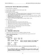
5.
Install the new screws and tighten.
CAUTION
Install the new drive with the screws included in the installation kit. Using the old screws
will damage the new drive. Old screws will interfere with operation of the MOD transport
mechanism.
6.
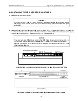
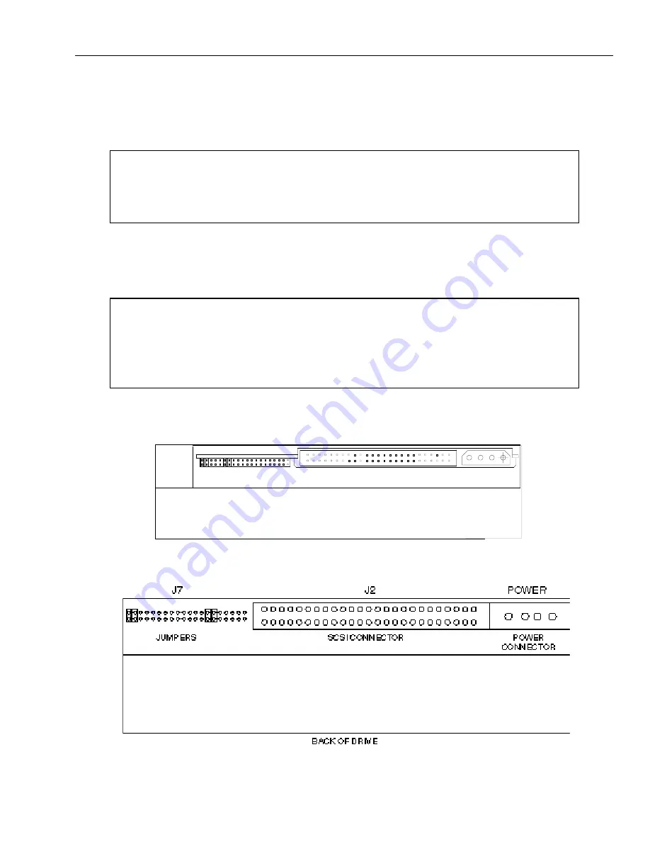
Install the power cable and the ribbon cable. Align the ribbon cable so that the red stripe (pin 1) on the cable
is located next to the power connector. The ribbon cable needs to be stretched and reversed when changing
from Pioneer to Maxoptix. The system will not boot if this is done incorrectly.
NOTICE
If you can not connect the ribbon cable to the MOD drive, or if you lack an accessible 50-
pin connector, refer to “Replacing a WORM drive” in section 2-3, "Removing the MOD".
Align the red stripe of the ribbon cable next to the power connector. Failure to do so will
prevent system boot-up.
Functional Switch
SCSI Connector
1
2
23
24
DC Power
1
ILLUSTRATION 2-5-A: Setting Drive Select Switches on Rear of Drive T5-2600P* Star
ILLUSTRATION 2-5-B: Setting Drive Select Switches on Rear of Drive T5-2600P
2
1
40
39
1


