background image

Direction 2233080, Rev 3

High Capacity MOD Option Installation Manual

i

Summary of Contents for MaxOptix T5-2600P Star Series

Page 1: ...GE MEDICAL SYSTEMS Copyright 1999 by General Electric Company Technical Publication Direction 2233080 Revision 3 GE Medical Systems High Capacity MOD Option Installation Manual ...

Page 2: ...This page intentionally left blank ...

Page 3: ...Direction 2233080 Rev 3 High Capacity MOD Option Installation Manual i ...

Page 4: ...ds into the Power Distribution Unit shall be performed by licensed electrical contractors Other connections between pieces of electrical equipment calibrations and testing shall be performed by qualified GE Medical personnel The products involved and the accompanying electrical installations are highly sophisticated and special engineering competence is required IMPORTANT X RAY PROTECTION In perfo...

Page 5: ...ual iii REVISION HISTORY REVISION DATE REASON FOR CHANGE 0 02 23 99 Initial Release 1 04 09 99 Changes per Design Review 2 11 20 99 Achieve Uniform Revision Numbers with Operator Addendum No Other Change 3 04 10 00 Added References to New MaxOptix Drive T5 2600P Star ...

Page 6: ...CONTENTS 1 1 3 MANPOWER 1 1 4 PERFORMANCE CHECK 2 1 5 WORK FLOW CHART 4 1 6 DOCUMENTATION 5 SECTION 1 REPLACING THE PIONEER DRIVE WITH THE MAXOPTIX DRIVE 6 2 1 SYSTEM SHUTDOWN 6 2 2 REMOVING THE SCSI TRAY 6 2 3 REMOVING THE MOD DRIVE 9 2 4 INSTALLING THE NEW MOD DRIVE 11 2 5 FIRMWARE VERIFICATION 15 2 6 SYSTEMS VALIDATION 16 2 7 RATING PLATE 16 ...

Page 7: ... A Setting Drive Select Switches on Rear of Drive T5 2600P Star 12 ILLUSTRATION 2 5 B Setting Drive Select Switches on Rear of Drive T5 2600P 12 ILLUSTRATION 2 6 A Rating Plate Location for all MR Systems and CT HiSpeed Advantage Z and HiLight Advantage 16 ILLUSTRATION 2 6 B Rating Plate Location for CT HiSpeed Advantage RP1 X and 2 X 17 LIST OF TABLES Table 1 1 CT and MR Genesis based Systems 1 T...

Page 8: ...S Check that the following items are included in the upgrade kit E8001ND 1 Maxoptix T5 2600P Star magneto optical disk MOD drive with g4 2 firmware OR 1 Maxoptix T5 2600P magneto optical disk MOD drive with g61a firmware 6 Mounting screws with washers for Maxoptix drive installation 1 Drive filler plate if replacing full height drives 2 screws for drive filler plate installation 2 nuts for drive f...

Page 9: ...stalling the Maxoptix drive upgrade 2 Perform a scan using a phantom 3 Save one exam one series and one image to the Pioneer media 4 View the exam series and image saved directly from the media by typing od on the accelerator line 5 View the exam series and image from the system disk by typing sd on accelerator line 6 Restore an exam one series and one image from the Pioneer media 7 View the exam ...

Page 10: ...on t attach RP 1 X OK OK OK OK OK OK Won t attach RP 2 X OK OK OK OK OK OK Won t attach HLA OK OK OK OK OK OK Won t attach CT i Note 1 Note 1 Note 1 Note 1 OK OK OK QX I Note 1 Note 1 Note 1 Note 1 OK OK OK AW 3 1 Note 1 Note 1 Note 1 Note 1 OK OK OK MR Systems MR 5 8 MR 5 4 MR LX8 2 AW 3 1 MR 5 8 OK OK OK Attaches but doesn t read MR 5 4 OK OK OK Attaches but doesn t read MR LX8 2 Note 1 Note 1 O...

Page 11: ...rive 2 3 4 Confirm SCSI ID 3 on new MOD drive 2 4 1 Install MOD drive where old drive was 2 4 3 Use screws with the kit to install new MOD drive 2 4 4 Install power and ribbon cables 2 4 5 Reinstall tape drive 2 4 6 Reconnect tape drive ribbon and power cables 2 4 7 Reinstall SCSI tray front cover 2 4 9 Re assemble computer covers 2 4 11 Verify firmware revision is g61a 2 5 Validate the system wor...

Page 12: ...on Manual 5 1 6 DOCUMENTATION The following documents are supplied with this kit Title Direction Maxoptix MOD Drive Replacement for Pioneer Installation Manual 2233080 100 High Capacity MOD Option User Guide Addendum 2233570 100 Table 1 3 Upgrade Documentation ...

Page 13: ...umerical order 3 Press the SHUTDOWN button on the plasma display A pop up message appears on the screen asking Really shut the scanner down Press the YES button to shut down the scanner Wait until you get to the prompt monitor level i e 4 Turn off the Genesis computer and then unplug the computer from the Genesis console 5 Remove the front cover from the Genesis computer The SCSI disk tape or cart...

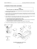
Page 14: ...derside of the SCSI tray as shown in Illustration 2 1 A or 2 1 B 3 Make note of where all the cables attach to the Serial I O Panel located on lower right side of cabinet front and disconnect all the cables from the panel 4 Loosen the four captive screws that hold the Serial I O Panel in place and remove the Panel 5 Disconnect the SCSI tray power connector from the underside of the SCSI tray as sh...

Page 15: ...t out of the cabinet so that the tray does not fall to the floor Lift carefully to avoid injury to yourself 7 Carefully withdraw the SCSI tray from the front of the cabinet as shown in Illustration 2 2 8 Put the SCSI tray flat onto a worktable PULL TRAY STRAIGHT OUT Removing the SCSI Tray ILLUSTRATION 2 2 NOTICE For MR systems that did not have the MOD drive option before you may need to order mou...

Page 16: ...f the tape or cartridge drive b Disconnect the power cable at the back of the tape or cartridge drive c Place the SCSI tray on its side with the tape or cartridge drive at the bottom d While supporting the tape or cartridge drive remove the four Phillips screws holding the tape or cartridge drive to the SCSI tray e Pull tape or cartridge drive and attached bracket out of the tray 3 Remove the MOD ...

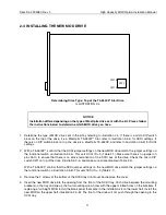
Page 17: ...OD drive 3 If the computer holds two Wren disk drives side by side in the back of the computer rearrange the ribbon cable so that there is a socket available for the MOD drive on the front Illustration 2 3 B a Disconnect the socket in the back of the Wren drive on the left b Loosen the bottom screws and remove the Wren drive on the left c Stretch out the ribbon cable underneath it and route to the...

Page 18: ...ctional switch on illustration 2 5 A This sets SCSI ID 3 Table 2 1 Make sure there is no jumper on pins 9 10 to ensure that there is no active termination of the SCSI bus at the drive Check the micro DIP switch SW1 on top of the drive Illustration 2 4 and make sure all are disabled Table 2 4 With a T5 2600P confirm that the SCSI jumper settings on the new MOD drive match the jumper settings on the...

Page 19: ...t to the power connector The ribbon cable needs to be stretched and reversed when changing from Pioneer to Maxoptix The system will not boot if this is done incorrectly NOTICE If you can not connect the ribbon cable to the MOD drive or if you lack an accessible 50 pin connector refer to Replacing a WORM drive in section 2 3 Removing the MOD Align the red stripe of the ribbon cable next to the powe...

Page 20: ...9 11 13 15 17 19 21 23 25 27 29 31 33 35 37 39 2 4 6 8 10 12 14 16 18 20 22 24 26 28 30 32 34 36 38 40 SCSI ID Bit 0 SCSI ID Bit 1 SCSI ID Bit 2 DEC TM MicroVAX TM Mode Disable Auto Spin Up Disable SCSI Bus Parity Enable Apple Macintosh Mode Disable Removable Media Report Disable Optical Device Type Report Enable ECC Verify after Write Disable Write Cache Disable Read Cache Enable Active Terminati...

Page 21: ...D Bit 0 SCSI ID Bit 1 SCSI ID Bit 2 Write with Verify Active Termination Drive Supplied Term Power SCSI Bus Term Power LED Pipe PwrDnAck Cart_In_Drive Cart_Loaded Stand Alone AC Installed Installed Removed Removed Removed Installed Installed Reserved Reserved Reserved Reserved Reserved Install Jumper to Enable Reserved for Jukebox Operation Table 2 3 MaxOptix T5 2600P Star Jumper Block Pin Assignm...

Page 22: ... tray c Reconnect the SCSI tray power connector on the underside of the SCSI tray d Hold the Serial I O Panel in place and tighten the four captive screws e Connect the cables to the Serial I O Panel as found at start of procedure f Reconnect SCSI cable to underside of tray 12 Reassemble computer covers 13 Power up computer 2 5 FIRMWARE VERIFICATION 1 Verify that the correct firmware revision is i...

Page 23: ... and image from the system disk by typing sd on accelerator line 7 Restore one exam one series and one image from the new media 8 View restored exam series and image 9 Detach media and eject 2 7 RATING PLATE 1 Once the system has been verified to be working properly using Archive put the rating plate sticker on the back of the computer in the location shown in Illustration 2 5 A for option upgrade...

Page 24: ...Direction 2233080 Rev 3 High Capacity MOD Option Installation Manual 17 RATING PLATE Rating Plate Location for CT HiSpeed Advantage RP1 X and 2 X ILLUSTRATION 2 6 B ...

Reviews: