GE Power Management
MDP Digital Time Overcurrent Relay
5-
3
GEK-100682D
5 PERIODIC & ACCEPTANCE TESTS
5
5.4 INSTANTANEOUS UNIT
a) VERIFICATION OF PICKUP
1.
Set the Output Select switch on the front of the relay to the B position so the output relays correspond to
phase or ground.
2.
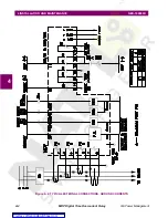
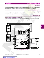
Connect the relay as indicated in Figure 5–1: TEST CONNECTIONS on page 5–1. Use a supply voltage
with a variable resistor in series, or use an electronic test source.
3.
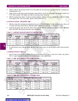
Set the relay at the minimum pickup TOC. Set the instantaneous unit to one times (1
×
) the pickup TOC
setting. Set the instantaneous time delay to zero (0) seconds.
4.
Apply current to the relay and verify that the Pickup LED lights and the output trip relay closes when the
current is between 95% and 105% of the pickup TOC setting.
5.
With the trip output contact closed, lower the applied current, verifying that the trip relay resets and that the
Pickup LED turns off at a current value equal to or greater than 95% of the pickup value.
b) VERIFICATION OF OPERATING TIME
1.
With the relay still connected as in Figure 5–1: TEST CONNECTIONS on page 5–1, apply a current of 5
times (5
×
) the pickup TOC setting, verifying that the operating time is less than 0.025 seconds.
2.
Set the time delay of the instantaneous unit and verify that it is never less than the set time, nor greater
than the set time +10 milliseconds.
5.5 GROUND UNIT
Repeat each test with the relay connected as in Figure 5–1: TEST CONNECTIONS on page 5–1, except apply
current to the ground unit (terminals 7 and 8). For each test, apply ground settings to the relay as instructed.


