GPA-9 manual
Interfaces
1.6
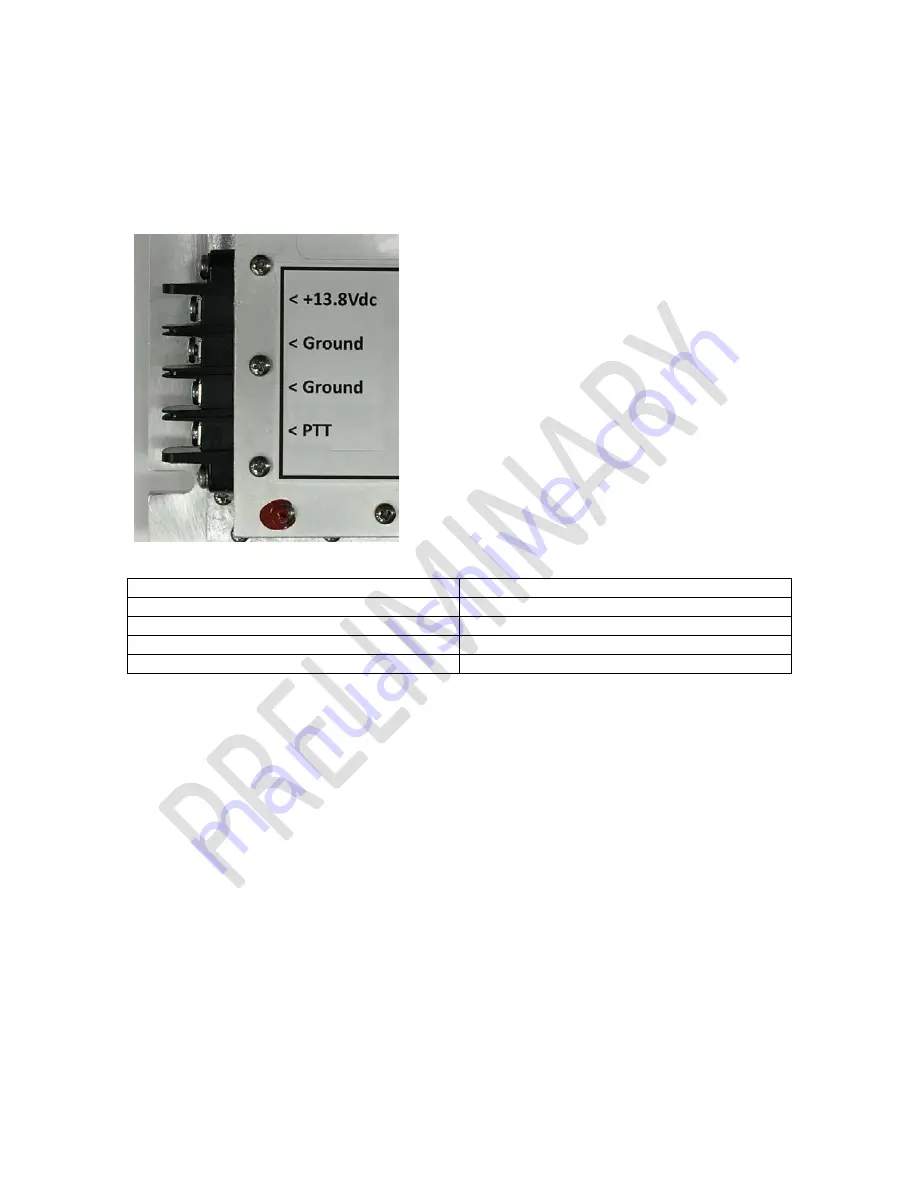
J102 Terminal Block
The J102 terminal block provides keying and power control signals.
Table 1 – J102 Control Cable Pin Functions
Pin
Function
Pin 1
13.8V nominal 10 amps DC input
Pin 2
Power supply Ground
Pin 3
ground
Pin 4
PTT (ground to transmit)
1.7
J100 RF Output
J100 is a 50 Ohm Female Type N connector.
1.8
J101 RF Input
J101 is a 50 Ohm Female Type N connector.
1.9
R138 Power Control Adjustment
R138 is used to adjust the RF power output of the amplifier in internal and mode. Turn the potentiometer
clockwise for higher power and counterclockwise for lower power. RF output power will depend on power
supply voltage (10-16V DC) and RF drive level (+27 to +30dBm)
1.10
LED Indicators
A pair of LED indicators are located next to the Power Adjustment. The lower indicator (GREEN) will
indicate that DC power is applied and the PA is in the receive state. The upper indicator (RED) will indicate
that the PA is in the transmit state. If both are on it indicates an Overtemperature fault. (See section 3.4)


