background image


Reference Manual


MDS 05-4446A01, Rev. 02

AUGUST 2008

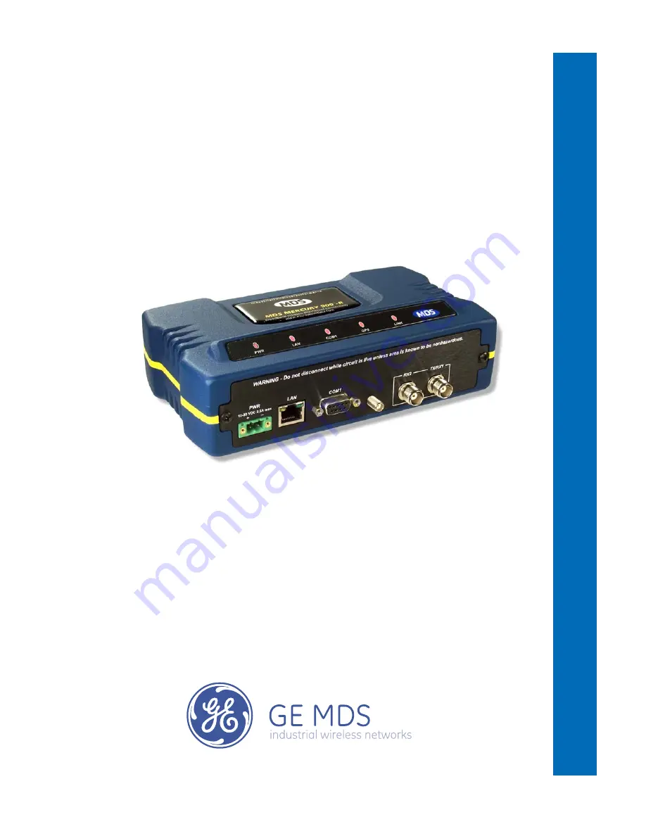
Wireless IP/Ethernet Transceiver

Covering AP and Remote Units

D R A F T

MDS Mercury Series

TM


Summary of Contents for MDS Mercury Series

Page 1: ...Reference Manual MDS 05 4446A01 Rev 02 AUGUST 2008 Wireless IP Ethernet Transceiver Covering AP and Remote Units DRAFT MDS Mercury SeriesTM ...

Page 2: ......

Page 3: ...ess LAN 8 1 3 3 Point to Point LAN Extension 9 1 3 4 Serial Radio Network Connectivity 9 1 3 5 Multiple Protocols and or Services 10 1 3 6 Wireless LAN with Mixed Services 11 1 3 7 Upgrading Older Wireless Network with Serial Interfaces 12 1 4 NETWORK DESIGN CONSIDERATIONS 12 1 4 1 Extending Network Coverage with Repeaters 12 1 4 2 Protected Network Operation using Multiple Access Points 14 1 4 3 ...

Page 4: ... Procedures 34 3 2 3 Navigating the Menus 38 3 3 BASIC OVERVIEW OF OPERATION 40 3 3 1 Starting Information Screen 40 3 3 2 Main Menu 42 3 4 CONFIGURING NETWORK PARAMETERS 43 3 4 1 Network Configuration Menu 43 3 4 2 Ethernet Port Configuration Menu 51 3 4 3 Bridge Configuration 52 3 4 4 SNMP Agent Configuration 53 3 4 5 AP Location Push Config Menu 55 3 4 6 SNTP Server Configuration 57 3 5 RADIO C...

Page 5: ... 1 TROUBLESHOOTING 135 4 1 1 Interpreting the Front Panel LEDs 135 4 1 2 Troubleshooting Using the Embedded Management System 136 4 1 3 Using Logged Operation Events 139 4 1 4 Alarm Conditions 140 4 1 5 Correcting Alarm Conditions 141 4 1 6 Logged Events 142 4 2 RADIO RF MEASUREMENTS 143 4 2 1 Antenna System SWR and Transmitter Power Output 143 4 2 2 Antenna Aiming For Directional Antennas 144 5 P...

Page 6: ... effective innovative reliable and of the highest quality possible We promise to build a relationship that is forthright and ethical one that builds confidence and trust Related Materials on the Internet Data sheets frequently asked questions case studies applica tion notes firmware upgrades and other updated information is available on the GE MDS Web site at www GEmds com About GE MDS Over two de...

Page 7: ...ATIONAL SAFETY NOTICES ERP Compliance To maintain regulatory compliance for Effective Radiated Power ERP of 1 Watt per MHz the following table of transmit power settings must be observed for the listed bandwidths and antenna types approved Consult the factory for other antenna options of lower gain CSA us Notice This product is approved for use in Class 1 Division 2 Groups A B C D Hazardous Locati...

Page 8: ... the FCC Rules and Regulations Any unauthorized modification or changes to this device without the express approval of Microwave Data Systems may void the user s authority to operate this device Furthermore the Mercury Series is intended to be used only when installed in accordance with the instructions outlined in this manual Failure to comply with these instructions may also void the user s auth...

Page 9: ...PS PPS Option 7 1 3 APPLICATIONS 7 1 3 1 Mobile Fixed Data System 8 1 3 2 Wireless LAN 8 1 3 3 Point to Point LAN Extension 9 1 3 4 Serial Radio Network Connectivity 9 1 3 5 Multiple Protocols and or Services 10 1 3 6 Wireless LAN with Mixed Services 11 1 3 7 Upgrading Older Wireless Network with Serial Interfaces 12 1 4 NETWORK DESIGN CONSIDERATIONS 12 1 4 1 Extending Network Coverage with Repeat...

Page 10: ...2 Mercury Reference Manual 05 4446A01 Rev C ...

Page 11: ...s many users need access to documents electronically This is especially useful when you need to access docu mentation while traveling or want to share a document with another user in the field Electronic documents also allow searching for a spe cific term or subject especially in larger manuals Access manuals for our equipment anytime from our Web site at www GEmds com Simply click the Downloads t...

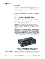
Page 12: ...where reliability and range are paramount The transceivers are commonly used to convey text documents graphics e mail video Voice over IP VoIP and a variety of other application data between mobile fixed point and WAN LAN based entities Based on multi carrier Orthogonal Frequency Division Multiplexing OFDM the transceiver features high speed low latency basic Quality of Service QoS for prioritizin...

Page 13: ...read spectrum transmissions others include data encryption enabling disabling channels and password protection Security is not a one step process that can simply be turned on and for gotten It must be practiced and enforced at multiple levels 24 hours a day and 7 days a week See GE MDS CYBER SECURITY SUITE on Page 16 for more information about the transceiver s secu rity tools Robust Radio Operati...

Page 14: ...ted by alarms High Speed 1 5 Mbps is over 100 times faster than 9 6 kbps radios Plug and Play Connectivity AP or Remote configuration requires minimal setup Built in GPS Receiver GPS technology is used for timing and location data The only external equipment needed for this func tionality is a GPS antenna several types are available from GE MDS 1 2 1 Model Offerings The transceiver comes in two pr...

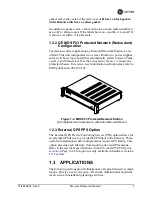
Page 15: ...chassis For system level information on this product refer to MDS publication 05 4161A01 Invisible place holder Figure 1 2 MDS P23 Protected Network Station incorporates two transceivers with automatic switchover 1 2 3 External GPS PPS Option The External GPS Precise Positioning Service PPS option allows for an external GPS device to provide the PPS input to the Mercury This is useful in installat...

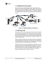
Page 16: ...the computer equipment con nected to the transceiver The Access Point is positioned at a location from which it communicates with all Remote units in the system Commonly this is a high location on top of a building or communications tower Messages are exchanged at the Ethernet level This includes all types of IP traffic A Remote transceiver can only communicate over the air to an Access Point AP P...

Page 17: ...a path for serial devices to migrate to IP Ethernet systems Many radio networks in operation today still rely on serial networks at data rates of 9600 bps or less These networks can use the transceiver as a means to continue using the serial service while allowing the infrastructure to migrate to an IP format A Remote transceiver with its serial port connected to a GE MDS serial based radio such a...

Page 18: ...s seamless simultaneous operation as shown in Figure 1 7 Invisible place holder Figure 1 7 Multiple Protocol Network MDS 4790 Master MDS 9790 Master MDS 9810 Master Serial Conn Serial Conn Serial Conn MDS 4710 Remote NMS Control Point SCADA Host Modbus IP HUB Access Point MDS 4710 Remote MDS 9710 Remote MDS 9710 Remote MDS 9810 Remote MDS 9810 Remote Remote Serial Remote Serial Remote Serial NETWO...

Page 19: ...s In extreme environments a simple NEMA enclosure is sufficient to house the unit The transceiver trades higher speed for longer range Commercial 802 11a b g solutions are designed to provide service to relatively small areas such as offices warehouses and homes They provide high data rates but have limited range The Mercury transmits at a higher power level uses a different frequency band has hig...

Page 20: ...ous GE MDS brand products had non standard signal lines on their interface connectors for example to control sleep functions and alarm lines These special func tions are not provided nor supported by the Mercury trans ceiver Consult equipment manuals for complete pinout information 1 4 NETWORK DESIGN CONSIDERATIONS 1 4 1 Extending Network Coverage with Repeaters What is a Repeater System A repeate...

Page 21: ...election beginning on Page 151 The following paragraphs contain specific requirements for repeater systems Antennas Two antennas are required at this type of repeater station one for each radio You must take measures to minimize the chance of interference between these antennas One effective technique for limiting interfer ence is to employ vertical separation In this arrangement assuming both ant...

Page 22: ...ove the loca tion of a store and forward repeater is also important A site must be chosen that allows good communication with both the Access Point and the outlying Remote site This can be on the top of a hill building or other elevated terrain from which all sites can be seen by the repeater station antenna A detailed discussion on the effects of terrain is given in Section 5 1 2 Site Selection b...

Page 23: ... It does however assure that only data destined for a unique network is passed through to that network Co Location for Multiple Networks It may be desirable to co locate Access Points at one location to take advantage of an excellent location that can serve two independent net works Configure each network with a unique Network Name and install each AP s antenna with at least 10 feet of vertical se...

Page 24: ... IEEE 802 1x device authentication Approved Remotes List local Only those remotes included in the AP list will associate Rogue AP where a foreign AP takes control of some or all remote radios and thus remote devices IEEE 802 1x device authentication Approved AP List A remote will only associate to those APs included in its local authorized list of APs Dictionary attacks where a hacker runs a progr...

Page 25: ...esigned for continuous service UL approved Input 120 220 Output 13 8 Vdc 2 5 A 01 3682A02 Omni Directional Antennas Rugged antennas well suited for use at Access Point installations Consult with your factory Sales Representative for details Yagi Antenna Directional Rugged antennas well suited for use at fixed Remote sites Consult with your factory Sales Representative for details GPS Receiving Ant...

Page 26: ...971A03 Flat Surface Mounting Brackets Screws Brackets 2 x 3 plates designed to be screwed onto the bottom of the unit for surface mounting the radio 82 1753 A01 Bracket screws 6 32 1 4 with locking adhesive Industry Standard MS 51957 26 70 2620 A01 Fuse Internal fuse 5 0 Ampere 29 1784A04 DIN Rail Mounting Bracket Bracket used to mount the transceiver to standard 35 mm DIN rails commonly found in ...

Page 27: ... 2 STEP 1 CONNECT THE ANTENNA PORTS 21 2 3 STEP 2 CONNECT THE PRIMARY POWER 22 2 4 STEP 3 CONNECT PC TO THE TRANSCEIVER 23 2 5 STEP 4 REVIEW TRANSCEIVER CONFIGURATION 23 2 5 1 Getting Started 23 2 5 2 Procedure 23 2 5 3 Basic Configuration Defaults 23 2 6 STEP 5 CONNECT LAN OR SERIAL DATA EQUIPMENT 24 2 7 STEP 6 CHECK FOR NORMAL OPERATION 26 ...

Page 28: ...20 Mercury Reference Manual 05 4446A01 Rev C ...

Page 29: ... is important to use a Network Name that is different from any currently in use in your area during the testing period To simulate data traffic over the radio network connect a PC or LAN to the Ethernet port of the Access Point and PING each transceiver several times 2 2 STEP 1 CONNECT THE ANTENNA PORTS Figure 2 1 shows the tabletop arrangement Connect the antenna ports of each transceiver as show...

Page 30: ...13 8 Vdc and 24 Vdc operation are listed in SPECIFICATIONS on Page 162 A Phoenix two pole power connector with screw terminals is provided with each unit Strip the wire leads to 6 mm 0 25 Be sure to observe proper polarity with the positive lead on the left and negative on the right as shown in Figure 2 2 NOTE The transceiver typically requires about 30 seconds to power up and might require severa...

Page 31: ...d test your data services 2 5 2 Procedure The following is a summary of the configuration procedure that must be done on each unit in the system Key parameters are shown on the Embedded Management System overview Figure 3 1 on Page 32 A lists of parameters is located in two tables Table 4 5 on Page 140 and Table 4 7 on Page 142 Detailed information on using the Management System can be found in MS...

Page 32: ...ce connectors on the front panel of the transceiver NOTE The use of shielded Ethernet cable is recommended for connection to the radio s ETH port The radio meets regulatory emission standards without shielded cable but shielding reduces the possibility of interference in sensitive environ ments and is in keeping with good engineering practice Table 2 1 Basic Configuration Defaults Item Menu Locati...

Page 33: ...ground and capable of pro viding at least 25 watts GPS ANTENNA PORT Coaxial connector SMA type for connection of a GPS receiving antenna Provides 3 5 Vdc output for compatibility with powered active GPS antennas Do not short this connector as you might cause damage to the internal power supply The GPS receiving antenna s gain must be 16 dBi or less NOTE GPS functionality is required on all Access ...

Page 34: ...te traffic flow Figure 2 4 shows a close up view of the transceiver s LED Indicator panel Table 2 2 provides details on each LED function Invisible place holder Figure 2 4 LED Indicator Panel If the radio network seems to be operating properly based on observa tion of the unit s LEDs use the PING command to verify the link integ rity with the Access Point Table 2 2 Transceiver LED Functions LED La...

Page 35: ...tes 100 Mbps operation GPS ON Internal GPS receiver is synchronized with the satellite network Blinking AP modem is synchronizing with the GPS timing OFF Internal GPS receiver is not synchronized with the satellite network LINK Access Point ON Default state OFF Not transmitting Usually occurs while waiting for GPS sync LINK Remote ON Associated to AP OFF Not associated with AP Table 2 2 Transceive...

Page 36: ...28 Mercury Reference Manual 05 4446A01 Rev C ...

Page 37: ...RS 43 3 4 1 Network Configuration Menu 43 3 4 2 Ethernet Port Configuration Menu 51 3 4 3 Bridge Configuration 52 3 4 4 SNMP Agent Configuration 53 3 4 5 AP Location Push Config Menu 55 3 4 6 SNTP Server Configuration 57 3 5 RADIO CONFIGURATION 58 3 5 1 Radio Configuration Menu 58 3 5 2 Serial Port Configuration 67 3 6 MODBUS TCP SERVER CONFIGURATION 80 3 6 1 Modbus TCP in Mercury Transceivers An ...

Page 38: ...ONFIGURATION REMOTE ONLY 98 3 10 DEVICE INFORMATION MENU 100 3 11 PERFORMANCE INFORMATION MENU 101 3 12 MAINTENANCE TOOLS MENU 113 3 12 1 Auto Firmware Upgrade Menu AP Only 124 3 13 PERFORMANCE OPTIMIZATION 127 3 13 1 Proper Operation What to Look For 129 ...

Page 39: ...on Page 43 Section 3 5 RADIO CONFIGURATION beginning on Page 58 Section 3 7 SECURITY CONFIGURATION MENU beginning on Page 85 Section 3 13 PERFORMANCE OPTIMIZATION beginning on Page 127 Section 3 12 MAINTENANCE TOOLS MENU beginning on Page 113 Each of these sections has a focus that is reflected in its heading The section you are now reading provides information on connecting to the Management Syst...

Page 40: ...mance Information NOTES Chart shows top level view only See Reference Manual for details Not all menu items are user configurable Serial Number Uptime Date Date Format Time Model Device Names Console Bd Rt UTC Time Offset Device Security Wireless Security Event Log Packet Statistics GPS Status Wireless Ntwk Stat Intl Radio Stat RM Performance Trend Manage Certif RADIUS Configuration Starting Infor...

Page 41: ...der Figure 3 3 View of the MS with a Browser Selections at left provide links to the various menus 3 2 ACCESSING THE MENU SYSTEM The radio has no external controls or adjustments All configuration diagnostics and control is performed electronically using a connected PC This section explains how to connect a PC log into the unit and gain access to the built in menus ...

Page 42: ...o a Local Console session You can run Telnet sessions locally or remotely through an IP connection Web Browser Connect a PC to the unit s LAN port either directly or via a network and launch a web browser session for example Internet Explorer Firefox etc Enter the IP address of the device to be managed into the browser s address field This method provides a graphical representation of each screen ...

Page 43: ... 115 200 bps data rate 8 data bits no parity One stop bit and no flow control Use ANSI or VT100 emulation TIP The HyperTerminal communications program can be accessed on most PCs by selecting this menu sequence Start Programs Accesso ries Communications HyperTerminal NOTE If the unit is powered up or rebooted while connected to a terminal you will see a series of pages of text information relating...

Page 44: ... IP address of the unit beforehand If you do not know the address use the Local Console method above and access the Starting Information Screen The address is displayed on this screen 1 Connect a PC to the unit s LAN port either directly with a crossover cable or via a network with a straight through cable The LAN LED lights to indicate an active connection NOTE When using Ethernet to access the u...

Page 45: ... not use punctuation mark characters You may use up to 13 alpha numeric characters Starting a Web Browser Session NOTE Web access requires that you know the IP address of the unit you are connecting to If you do not know the address start a Local Console session see Starting a Local Console Session Recommended for first time log in on Page 35 and access the Starting Information Screen The IP addre...

Page 46: ...n Figure 3 8 From here you can review basic informa tion about the unit or click one of the menu items at the left side of the screen Invisible place holder Figure 3 8 Starting Information Screen Web Browser Example 3 2 3 Navigating the Menus Via Terminal Telnet or SSH Sessions Recommended for first time log in Local Console Telnet and SSH sessions use multi layered text menu systems that are near...

Page 47: ...r change your mind before pressing the key simply press to restore the previous value In some cases when you type a letter to select a parameter you will see a prompt at the bottom of the screen that says Choose an Option In these screens press the keyboard s to step through the available selections When the desired option appears press the key to choose that selection In some cases you can change...

Page 48: ...r and its current operating conditions Figure 3 9 Starting Information Screen AP screen shown Remote similar differences noted below Device Mode Operating mode of the unit as it relates to the radio network Device Name This is a user defined parameter that appears in the heading of all pages To change it see Network Configura tion Menu on Page 43 Current IP Address Unit s IP address 169 254 0 2 De...

Page 49: ...to the left of the Device Status field Pressing the A key on your keyboard takes you directly to the Current Alarms screen Associated Remotes AP Only Indicates the number of Remotes that have achieved association with the AP Connection Status Remote Only Indicates whether the Remote has an RF connection with an AP Satellite Fix Status Indicates whether internal GPS receiver has achieved synchroniz...

Page 50: ...Tools to configure the wireless radio layer of the transceiver See RADIO CONFIGURATION on Page 58 Serial Port Configuration Menus for tailoring the COM1 port for data mode operation data only See Serial Port Configura tion on Page 67 Security Configuration Tools to configure the security services available with the transceiver s environment See SECURITY CONFIGURATION MENU on Page 85 Redundancy Con...

Page 51: ...d set as necessary before placing a transceiver into service Figure 3 11 Network Configuration Menu Network Interface Config Presents a menu where you can view or set various parameters VLAN Status IP Configuration and DHCP Server Configuration Ethernet Port Config Presents a menu for defining the status of the Ethernet port enabled or disabled port follows association and Ethernet filtering confi...

Page 52: ...le time offset 0 NOTE The Mercury gets time of day data from the GPS receiver if the receiver gets a satellite fix Network Interface Configuration Submenu Invisible place holder Figure 3 12 Network Interface Configuration Submenu VLAN Status This selection is used to enable or disable virtual LAN operation For details refer to VLAN Configuration Menu on Page 45 enable disabled disabled IP Configur...

Page 53: ...EE 802 1Q standard When VLAN Status is enabled the wireless port of both AP and remote radios act as a trunk port The Ethernet port of an Access Point radio is normally configured as a trunk port This type of port expects incoming frames to have a VLAN ID tag and sends outgoing frames with a VLAN tag as well The Ethernet port of a Mercury radio can be configured as an access port or as a trunk por...

Page 54: ...Auto Management VLAN ID Defines the VLAN ID for traffic directed to the radio itself other than the terminal server process This VLAN ID is used for filtering and for tagging purposes 1 4094 2 Data VLAN ID Defines the VLAN ID assigned to traffic directed to and from the Ethernet port and the terminal server process in the radio This VLAN ID is used for filtering and tagging pur poses 1 4094 3 Defa...

Page 55: ...e IP address of this device Only static IP addressing mode is available when VLAN Status is enabled Static Dynamic Static Static IP Address The IPv4 local IP address 192 168 1 1 Static IP Netmask The IPv4 local subnet mask This value is used when the radio attempts to send a locally initiated message either from the terminal server or from a management process 255 255 0 0 The lower three lines of ...

Page 56: ...should be only one active DHCP server in a network If more than one DHCP server exists network devices might randomly get their IP address from different servers every time they request one NOTE Combining DHCP and IEEE 802 1x device authentication might result in a non working radio if the DHCP server is located at a Remote radio If possible place the DHCP server at the AP location A DHCP server c...

Page 57: ...st 0 0 0 0 DHCP starting address Lowest IP address in the range of addresses provided by this device 0 0 0 0 DHCP ending address Highest IP address in the range of addresses provided by this device A maximum of 256 addresses is allowed in this range 0 0 0 0 DHCP DNS address Domain Name Server address provided by this service DHCP WINS address Windows Internet Naming Service server address provided...

Page 58: ...he current addressing configured at the transceiver Current IP Gateway only displays on this screen if Default Route IF on the Network Interface Config menu Figure 3 13 on Page 46 is set to Data Invisible place holder IP Configuration Menu Figure 3 18 IP Configuration Menu CAUTION Changes to the following parameters while communicating over the network LAN or over the air might cause a loss of com...

Page 59: ...the Ethernet interface to allow traffic awareness and availability of the backhaul network for redundancy purposes NOTE The transceiver s network port supports 10BaseT and 100BaseT connections Confirm that your hub switch is capable of auto switching data rates To prevent excessive Ethernet traffic from degrading perfor mance place the transceiver in a segment or behind routers Figure 3 19 Etherne...

Page 60: ...onfiguration Menu Enable Filtering Activates Ethernet filtering enabled disabled disabled Address 1 2 3 4 Ethernet address fields When filtering is enabled the Mercury only accepts traffic on its Ethernet port from the configured addresses Valid IP address string 3 4 3 Bridge Configuration Invisible place holder Figure 3 21 Bridge Configuration Menu Bridge Priority View set the priority of the bri...

Page 61: ...r SNMP man ager There are textual conventions common files and specific files This allows the flexibility to change areas of the MIB and not affect other existing installations or customers msdreg mib MDS sub tree registrations mds_comm mib MDS Common MIB definitions for objects and events common to the entire product family mercury_reg mib MDS sub tree registrations mercurytrv1 mib SNMPv1 enterpr...

Page 62: ...ng pass words locally or initially for all cases on reboot This is the SNMPv3 password used for Authentication currently only MD5 is supported This string can contain up to 30 alpha numeric characters V3 Privacy Password Privacy password stored in flash memory Used when the SNMP Agent is managing passwords locally or initially for all cases on reboot This is the SNMPv3 password used for privacy DE...

Page 63: ...Manager 1 4 Table of up to four locations on the net work to which traps are sent Any standard IP address NOTE The number in the upper right hand corner of the screen is the SNMP Agent s SNMPv3 Engine ID Some SNMP Managers may need to know this ID in order interface with the trans ceiver s SNMP Agent The ID only appears on the screen when SNMP Mode is either v1 v2 v3 or v3_only NOTE For more SNMP ...

Page 64: ...ote radio to determine which Access Point to connect to when operating in Hopping w Hand offs mode The AP Locations file is a simple text file containing information about the location and configuration of all Access Points that the Remote can associate with The file is filled in by creating AP definition blocks using tags and labels The AP tag is used to begin a definition block and the AP tag en...

Page 65: ...at the Access Point to limit which channels are active If all channels are used you can leave out the CHANNELS statement You can leave out the BW statement for APs that are configured to 1 75 MHz bandwidth You can also leave out the DUR statement for APs that are configured with a 20 millisecond frame duration The following shows the syntax of the AP Locations file Mercury Remote AP Locations file...

Page 66: ...r address Press the Return key to make the address entry active 3 5 RADIO CONFIGURATION There are two primary layers in the transceiver network radio and data Since the data layer is dependent on the radio layer working prop erly configure and set the radio items before proceeding This section explains the Radio Configuration Menu Figure 3 26 for AP Figure 3 27 for Remote 3 5 1 Radio Configuration...

Page 67: ...atory limitations and losses in antenna transmission line See How Much Output Power Can be Used on Page 155 for information on how to calculate this value 0 30 30 Receive Power AP Only View set the receiver gain setpoint for the expected strength of incoming signals from Remotes This setting indicates at what level in dBm the AP expects to hear the Remote stations A setting of 70 would set the AP ...

Page 68: ...ncy Mode Selection Single Channel Static Hopping Hopping w Hand offs Examples of all three screens are provided below followed by a description of the menu items Invisible place holder Figure 3 28 Frequency Control Menu Single Channel Freq Mode Invisible place holder Figure 3 29 Frequency Control Menu Static Hopping Freq Mode ...

Page 69: ...requires a radio reboot Static Hopping Hopping with Hand offs Single Channel Single Channel NOTE Frequency Mode Static Hopping on Access Points requires TDD Sync Mode GPS Required Channel Frequency Allocations for Single Channel operation are shown in Table 3 1 The transceiver utilizes up to 14 chan nels 0 13 depending on the bandwidth used 1 75 MHz or 3 5 MHz Table 3 1 Channel Frequency Allocatio...

Page 70: ... that setting a 3 5 MHz bandwidth radio to operate at 1 75 MHz bandwidth will cause a slight degradation of interference rejection capabil ity 1 75MHz 3 5MHz Hop Pattern Selects a pre defined series of channels that is fol lowed when hopping Hop Pattern Offset Inserts an offset into the hop pattern that is synchronized with the GPS For example if the offset is 0 then the start of the pattern is al...

Page 71: ...ng which prevents AP to AP interfer ence Changing this parameter requires a radio reboot Free Run GPS Required Free Run Note Do not use the Prefer GPS setting Channel Selection Opens a submenu where you can specify channel usage Single Frequency Channel The RF frequency that the integrated radio will operate on when in single frequency non hopping mode 0 to 6 for 3 5 MHz 0 to 13 for 1 75 MHz 0 Fra...

Page 72: ...Strict Signal Signal and Distance Signal Dis tance and Bearing Description The Remote always chooses the closest AP regardless of connection status RSSI etc The Remote will only choose a new AP when the modem link is lost The Remote chooses a new AP when the modem link is lost or when the RSSI or SNR falls below the threshold The Remote then chooses the closest AP Operates the same way as the Stri...

Page 73: ...whether over the air data packets will be compressed enabled disabled enabled Max Modulation Sets the highest modulation speed the trans ceiver will use BPSK QPSK 1 2 QPSK 3 4 16QAM 1 2 16QAM 3 4 64QAM 2 3 64QAM 3 4 QAM16 3 4 Cyclic Prefix Amount of additional information added to the over the air packets to mitigate the effects of channel multipath 1 4 1 8 1 16 1 32 1 16 Channel Type This paramet...

Page 74: ...di fies the downlink split in response to the traffic load When more traffic is flowing upstream the downlink split changes to allocate additional capacity to the uplink When more traffic is flowing downstream the downlink gets additional capacity If TDD synchronization is used to synchronize Access Points and minimize inter Access Point interference Adaptive Split should be disabled enabled disab...

Page 75: ...arent encapsulation over IP In this capacity it acts as a gateway between serial and IP devices Two common scenarios are PC applica tions using IP to talk to remote devices and serial PC applications talking to remote serial devices over an IP network These data services are available from the COM1 port of the radio COM1 Port Dual Purpose Capability The COM1 port is used as a local console connect...

Page 76: ...tion or IP tunneling provides a mechanism to encapsulate serial data in an IP envelope All bytes received through the serial port are put into the data portion of a TCP or UDP packet TCP or UDP are user configurable options In the same manner all data bytes received in a TCP or UDP packet are output through the serial port When the radio receives data through the serial port it is buffered until t...

Page 77: ...ship reports but responds to both V1 and V2 que ries The Point to Multipoint Serial to Serial Application Example on Page 76 shows how to provide multicast services Data Buffering Data buffering is always active regardless of the selected mode If you connect EIA 232 serial devices to the transceiver review these parame ters carefully Serial Configuration Wizard GE MDS recommends the Serial Configu...

Page 78: ... options Varies depending on the selected IP protocol Configuring for UDP Point to Multipoint Invisible place holder Figure 3 34 UDP Point to Multipoint Menu Use UDP point to multipoint to send a copy of the same packet to mul tiple destinations such as in a polling protocol Status Enable Disable the serial data port Mode The type of IP port offered by the transceiver s serial device server TCP UD...

Page 79: ... 64 000 30010 Talkback Enable Talkback is a mode where the radio returns a serial message received within a time out period back to the last address of an incoming UDP message If the time out expires the unit sends the serial data to the configured address Enable Disable Disabled Baud Rate Data rate payload for the COM port in bits per second 1 200 115 200 19200 Byte Format Formatting of data byte...

Page 80: ...ata packets received through the serial port on the transceiver 1 64 000 30010 Local IP Port Port number where data is received and passed through to the serial port The application connecting to this transceiver must use this port number 1 64 000 30010 Packet Redundancy Mode For proper operation all radios Serial Packet Redundancy mode must match Single Packet mode vs Packet Repeat mode This is b...

Page 81: ...rough the serial port on the transceiver Any valid IP port 30010 Secondary Host Address The IP address to be used as a desti nation for data received through the serial port in case the primary host address is not available Any legal IP address 0 0 0 0 Secondary IP Port The destination IP port for data packets received through the serial port on the transceiver used along with the secondary host a...

Page 82: ...pe of IP port offered by the transceiver s serial device server TCP UDP TCP Local Listening IP Port Receive IP data from this source and pass it through to the connected serial device The applica tion connecting to the local TCP or UDP socket must use this port number Any valid IP port 30010 Baud Rate Data rate payload for the COM port in bits per second 1 200 115 200 19200 Byte Format Interface s...

Page 83: ...3 4 NOTE The TCP session has a timeout of 10 minutes 600 seconds If inactive for that time the session is closed The transceiver offers the port again for connection after this time expires Establishing a Connection From the PC establish a TCP connection to the IP address of the Remote transceiver and to the IP port as configured above 30010 Use a Telnet client application to establish this connec...

Page 84: ... to serial application except that it uses multicast addressing The primary difference is that data presented at the Access Point s COM port is packetized and sent using UDP to all of the Remotes Upon receiving the packet all of the Remotes strip the data from the UDP packet and send it out their COM ports Likewise data presented at any of the Remotes COM ports is packetized sent to the EIA 232 RT...

Page 85: ... LA N COM 1 COM 2 PW R LIN K Remote LA N COM 1 COM 2 PW R LIN K Remote Table 3 6 Serial Port Application Configuration Transceiver Location Menu Item Setting Access Point COM1 Status Enabled Baud Rate 9600 Example Flow Control Disabled IP Protocol UDP Remote IP Address 224 254 1 1 Multicast Address1 Remote IP Port 30010 Local IP Port 30010 Remote Units COM1 Enable Enabled Baud Rate 2 400 Example F...

Page 86: ...ansceiver in a single network can run in both modes at the same time In other words you can configure some Remotes for TCP mode and others along with the Access Point for UDP mode In this configuration the Host PC can use both data paths to reach the RTUs This is helpful when a mixed collection of RTUs is present where some RTUs can operate in a broadcast form while others cannot see Figure 3 43 o...

Page 87: ...nsceiver LA N COM 1 COM 2 PW R LIN K Remote 1 LA N COM 1 COM 2 PW R LIN K Remote 2 LA N COM 1 COM 2 PW R LIN K Remote 3 LA N COM 1 COM 2 PW R LIN K Remote 4 Table 3 7 Serial Port Application Configuration Transceiver Location Menu Item Setting Access Point Status Enabled Baud Rate 9 600 Flow Control Disabled IP Protocol UDP Send to Address A multicast IP address such as 224 254 1 1 Send to Port 30...

Page 88: ... web site for additional information www modicon com TECHPUBS intr7 html NOTE Modbus TCP functionality is provided on the COM1 port of the transceiver only 3 6 1 Modbus TCP in Mercury Transceivers An Overview The transceiver implements a Modbus TCP server that bridges Modbus TCP to either Modbus RTU or Modbus ASCII It does not function as a Modbus TCP client The transceiver converts Modbus TCP req...

Page 89: ...lect A to begin the wizard Invisible place holder Figure 3 44 Configuration Wizard Opening Screen 2 Choose the IP protocol you wish to use TCP UDP or Mod bus TCP by selecting the appropriate letter from the menu Figure 3 45 IP Protocol Selection Screen 3 On the next screen Figure 3 46 on Page 82 choose the listening port you wish to use for the Modbus TCP server The default is port 502 Press N to ...

Page 90: ...formats MODBUS RTU or MODBUS ASCII Press B to enter the Modbus serial timeout value in milliseconds Press N to continue the wizard NOTE The only difference between Modbus RTU and Modbus ASCII is the form of the framing sequence error check pattern and address interpretation Figure 3 47 Choose Modbus Serial Format and Timeout Value Note Modbus Timeout setting is in milliseconds not seconds as displ...

Page 91: ...te and Byte Format 6 The screen shown in Figure 3 49 appears next Press A to select the Buffer Size of message packets and B to select the Inter Frame Delay Press N to continue with the wizard Invisible place holder Figure 3 49 Buffer Size and Inter Frame Delay Values 7 On the next screen Figure 3 50 on Page 84 select A and use the spacebar to enable the serial port for data communication Press N ...

Page 92: ...ew all settings on the summary screen shown in Figure 3 51 If all settings are correct press X to confirm and exit the wizard If not select the letter of the item s you wish to change Invisible place holder Figure 3 51 Serial Configuration Summary Screen This completes the menu selections for Modbus TCP operation ...

Page 93: ...y Controls how and when radios communicate with each other as well as how data traffic is handled RADIUS Configuration Deals with IEEE 802 1x device authentication and authorization using a central server Manage Certificates Remote only Allows setting of certificate types download paths and TFTP parameters Invisible place holder Figure 3 52 Security Configuration Menu Selecting any of the Security...

Page 94: ...ess to the Secure Shell SSH server enabled disabled enabled HTTP Mode Controls access to the transceiver s management system via the web server disabled HTTP HTTPS HTTP HTTP Auth Mode Selects the mode used for authenticating a web user Basic Auth MD5 Digest Basic Auth User Auth Method View set the method of authentication for users Local Radius Local User Auth Fallback View set method of authentic...

Page 95: ... string up to 13 characters guest TIP For enhanced security consider using misspelled words a combi nation of letters and numbers and a combination of upper and lower case letters Also the more characters used up to 13 the more secure the password These strategies help protect against sophisticated hackers who use a database of common words for example dictionary attacks to determine a password 3 ...

Page 96: ...g over the air payload any alpha numeric string of 8 to 15 characters empty Max Remotes AP only The maximum number of remotes an AP can associate with Approved Remotes AP only Launches a submenu where you can view add or delete approved Remotes See Figure 3 56 Approved Remotes Submenu Setting the Device Auth Mode to Local forces an AP to check the Approved Remotes List before establishing a radio ...

Page 97: ...th this AP 3 7 3 IEEE 802 1x Device Authentication This section covers the configuration needed for the radios to access the IEEE 802 1x device authentication server which provides Device Level Security and for Wireless Access Security GE MDS does not provide the server software Operation of Device Authentication Device authentication forces the radio to authenticate before allowing user traffic t...

Page 98: ... received from the authentication server data from the Remote passes Remote When Device Auth Method is set to RADIUS the Remote halts any data it is passing and requests Authentication from the device authenti cation server If accepted data is transmitted Operation of User Authentication User Authentication controls authentication of users who can manage the device This is in contrast to Device Au...

Page 99: ...e appropriate files on the authentication server empty any alpha numeric string up to 16 characters User Auth Mode RADIUS Authentication algorithm PAP CHAP EAP PAP NOTE CHAP is more secure than PAP PAP may display the login password in log files at the authentication server while CHAP will encrypt the login password 3 7 4 Manage Certificates Use Certificate generation software to generate certific...

Page 100: ...present in each of the Remote radios Use the commands described below to install these files into each Remote radio Certificate Type Selects one of the three certificate file types mentioned above Root CA Client Private Key Root CA Certificate Filename Specifies the software path and filename for downloading certificates Retrieve Certificate Initiates the retrieval of the certificate file from the...

Page 101: ...nt of data sent in each TFTP packet 3 8 REDUNDANCY CONFIGURATION AP ONLY For operation in protected redundant mode an AP must be in a Pack aged P23 enclosure with a backup radio See MDS publication 05 4161A01 for details This manual is available under the Downloads tab at www GEmds com The Redundancy Configuration Menu Figure 3 60 is where you enable disable redundancy operation and define the tri...

Page 102: ...gger sta tus for Radio Events such as a loss of associated Remotes or excessive packet errors Hardware Event Triggers This selection opens a submenu Figure 3 63 on Page 96 where you can set view the trigger sta tus for initialization hardware errors Redundancy Configuration Options This selection opens a sub menu Figure 3 64 on Page 96 where you can set the threshold criteria for declaring an erro...

Page 103: ...gers Invisible place holder Figure 3 62 Radio Event Triggers Lack of associated remotes exceeded threshold This setting deter mines whether or not a switchover occurs when a lack of asso ciated Remote units exceeds the time period set in Figure 3 65 on Page 97 enabled disabled disabled Packet Receive Errors exceeded threshold This setting determines whether or not a switchover occurs when the numb...

Page 104: ...isabled Redundancy Configuration Options Menu Use this menu Figure 3 64 to set the thresholds for the Lack of Asso ciated Remotes and Packet Receive Errors Selecting either item opens a submenu where you can view or change settings Invisible place holder Figure 3 64 Redundancy Configuration Options Menu Lack of Associated Remotes Exceeded Threshold This selection opens a submenu Figure 3 65 where ...

Page 105: ...ed Threshold Menu Invisible place holder Figure 3 65 Lack of Associated Remotes Exceeded Threshold Menu Lack of Remotes for Select this item to change the time setting in seconds for a lack of associated Remotes When there are no associated Remotes for a period exceeding this time a redun dancy switchover occurs 60 500 500 Packet Receive Errors Exceeded Threshold Menu Invisible place holder Figure...

Page 106: ...y Stream GPS to Console Used to enable disable streaming of GPS NMEA data to the console port COM1 Baud rate is 4800 baud when Stream GPS to console is enabled enabled disabled disabled GPS to Console Baud Rate The serial baud rate when GPS streaming is enabled Send GPS via UDP Used to enable disable sending GPS NMEA data to a server via UDP enabled disabled disabled GPS UDP Server IP Address Spec...

Page 107: ...formation GSA Polling Seconds between GSA string outputs the overall satellite data GSV Polling Seconds between GSV string outputs the detailed satellite data RMC Polling Seconds between RMC string outputs the recom mended minimum data VTG Polling Seconds between VTG string outputs the vector track and speed over ground MSS Polling Seconds between MSS string outputs the beacon receiver status info...

Page 108: ... able Value lost with power failure if SNTP Simple Network Time Protocol server not accessible Time Current time of day User setable Setting HH MM SS Value lost with power failure if SNTP server not accessible Date Format Select presentation format Generic dd Mmm yyyy European dd mm yyyy US mm dd yyyy Console Baud Rate Used to set display data communications rate in bits per second between a conne...

Page 109: ...nsceiver as the Realm name for network login web browser only and menu headings Contact User defined appears on this screen only Location User defined appears on this screen only Description User defined appears on this screen only 3 11 PERFORMANCE INFORMATION MENU The Performance Information Menu Figure 3 71 on Page 102 is the entry point for a series of submenus where you can evaluate transceive...

Page 110: ...d and unit location data See Figure 3 77 on Page 107 for details Wireless Network Status Current AP association state and MAC address See Figure 3 79 on Page 109 for details Internal Radio Status Remote Only Shows connection status RF parameters and total FEC count for the unit See Figure 3 84 on Page 111 for details Performance Trend Remote Only Launches a continuously updated list of performance...

Page 111: ...05 4446A01 Rev C Mercury Reference Manual 103 Invisible place holder Figure 3 72 Performance Trend Screen Invisible place holder Figure 3 73 Bridge Status Menu ...

Page 112: ...e challenge question Send File y n before the request proceeds Event Log Host Address Set display the IP address of the TFTP server any valid IP address 0 0 0 0 Event Log Filename Set display the name of the event log file on the TFTP server any valid filename eventlog txt Transfer Options A menu for configuring the TFTP transfer Syslog Server Address Use this selection to set or view the IP addre...

Page 113: ...and date from a Time Server This server is typically a standard Win dows PC server SNTP application In the absence of the SNTP services the user must manually enter time and date information at the Access Point See DEVICE INFORMATION MENU on Page 100 for SNTP server identification The manually set time and date clock relies on the unit s primary power A loss of power resets the clock to 02 Jan 200...

Page 114: ...e to transmissions corrupted by RF interference Ethernet colli sions or degradation If significant Ethernet Receive Errors are observed check the quality of your Ethernet cabling and con nectors or that you do not have cable lengths exceeding the specification limits Lost Carrier Detected This parameter reports how many times the wired Ethernet connection has lost link Clear Ethernet Statistics Re...

Page 115: ...ites orbiting the Earth twice a day only a sub set of these is visible to a receiver at a given location A good signal provides information from six to ten satellites Latitude Shows the transceiver s latitudinal location in degrees based on GPS data received from the satellites Longitude Shows the transceiver s longitudinal location in degrees based on GPS data received from the satellites Altitud...

Page 116: ...l oper ation the Remote monitors the channel for Access Point transmissions The Remote synchronizes its power timing and frequency to the Access Point then requests access to the network The Access Point and Remote check each other s authorization and authentication according to the configuration of the Device Authorization and Encryption Enable parameters and the Network Name parameter The Remote...

Page 117: ...ated with the AP PA Temperature Shows the power amplifier temperature in degrees Celsius Remote Database AP Only Displays a submenu where associ ated Remotes are listed in table form according to their number operational state MAC address IP address and name if assigned See Figure 3 81 on Page 110 Remote Performance Database AP Only Displays a submenu where associated Remote performance data is li...

Page 118: ...ided in Table 4 3 on Page 138 Current AP Eth Address Displays the Ethernet MAC address of the current AP Current AP IP Address Shows the IP address of the current AP Current AP Name Displays the device name of the current AP Time Connected Shows the time at which the remote connected to the AP The Remote has been continually connected since this time Invisible place holder Figure 3 81 Remote Datab...

Page 119: ...the Remote station has associated with an AP Associated Scanning Ranging Con necting Authorizing Current AP Name Shows the Device Name of the current AP Transmit Power Shows the RF power output from the transmit ter The AP changes the transmit power of the Remote to match the desired receive power at the APs receiver This provides end to end power control Average RSSI Shows average received signal...

Page 120: ...se ratio SNR in dB TX Frequency Offset Shows the RF carrier shift of the Remote s transmitter measured in Hertz Hz The transmitted frequency is continually reviewed and adjusted to agree with what the AP expects to see This optimization results in more efficient oper ation corrects for doppler shift and results in higher throughput between AP and Remote stations RX Frequency Offset This is a measu...

Page 121: ...ain ing unit operating parameters settings See Configuration Scripts Menu on Page 119 Ping Utility Diagnostic tool to test network connectivity See Ping Utility Menu on Page 122 Authorization Codes Alter the unit s overall capabilities by enabling the built in resources See Authorization Codes on Page 123 Reset to Factory Defaults Restores parameters to factory default settings See Reset to Factor...

Page 122: ...upgrades to the transceiver firmware Loading new firmware into the unit will not alter any privileges pro vided by Authorization Keys and does not require you to take the trans ceiver off line until you want to operate the unit with the newly installed firmware image Firmware images are available free of charge at www GEmds com Resources TechnicalSupport NOTE Firmware for AP radios is different th...

Page 123: ...d place it in service whenever you desire Invisible place holder Figure 3 89 Reprogramming Menu TFTP Host Address IP address of the host computer from which to get the file Any valid IP address This same IP address is used in other screens functions reprogramming logging etc Changing it here also changes it for other screens functions Firmware Filename Name of file to be received by the TFTP serve...

Page 124: ...e radios or vice versa This was only true for earlier pre 2 1 0 firmware To install firmware by TFTP you will need A PC with a TFTP server running The IP address of the PC running the TFTP server A valid firmware file The IP address of the radio can be found under the Management System s Starting Information Screen See Starting Information Screen on Page 40 A TFTP server is available on the GE MDS...

Page 125: ...ansceiver Regardless of your connection to the transceiver loading firm ware configuration files into the unit s flash memory is much slower than loading software onto a PC hard drive or RAM Upgrade Procedure To load a new firmware file filename mpk into the transceiver use the following procedure LAN PORT LOCAL WINDOWS PC WITH CONFIG FILES IP ADDRESS 172 0 0 A IP ADDRESS 172 0 0 B TFTP SERVER TEL...

Page 126: ... Maintenance Menu Reprogramming Menu Retrieve File Status messages on the transfer are posted on the Management Sys tem screen NOTE The new firmware image file that replaces the Inactive Image file is automatically verified 6 Reboot the transceiver Main Menu Maintenance Menu Reprogramming Menu Reboot Device 7 Test the transceiver for normal operation End of Procedure Error Messages During File Tra...

Page 127: ...nformation when you contact the factory for technical support A technician can often spot poten tial problems by reviewing a configuration file How Configuration Files Work When a configuration script file is downloaded to a radio Retrieve File the radio executes the parameters as commands and takes the values contained in it When a configuration script file is uploaded from the radio Send it cont...

Page 128: ...ore exporting a unit s configuration name it in a way that reflects the radio s services or other identification Transfer Options A menu for configuring the TFTP transfer Category The category of parameters to send or receive Retrieve File Initiate the file transfer of the configuration file from TFTP server into the transceiver Send File Initiate the file transfer from the transceiver s current c...

Page 129: ...o change from the default value Change only the parameter values Capitalization counts in some field parameters Comment Fields a Edit or delete anything on each line to the right of the comment delineator the semicolon b Comments can be of any length but must be on the same line as the parameter or on a new line that begins with a semicolon character c Comments after parameters in files exported f...

Page 130: ...alid IP address Count Number of Ping packets to be sent Packet Size Size of each Ping data packet bytes Ping Send Ping packets to address shown on screen This screen is replaced with a detailed report of Ping activity see example in Figure 3 94 Press any key after viewing the results to return to this menu Invisible place holder Figure 3 94 Ping Results Screen ...

Page 131: ...e the Reset to Factory Defaults selection on the Maintenance Tools Menu to return all configurable settings to those set at the factory prior to shipping Use this selection with caution as you will lose any custom settings you have established for your transceiver and will need to re enter them using the menu system To prevent accidental use of the command a challenge question is presented at the ...

Page 132: ...s all of the Remotes associated to this AP to read the AP s specified by Firmware for Upgrade firmware version active or inactive and download it via TFTP to the inactive image if the Remote does not already have that firm ware version Firmware Autoboot Boot connected remotes to Firmware for Upgrade see below Reboot Remotes Determines how a Remote behaves once it has downloaded new firmware from t...

Page 133: ...ire network The Test Mode function is automatically limited to 10 minutes Only use Test Mode for brief measurements Radio Mode Sets displays the radio s operating mode To change the setting press A on the PC s keyboard and press the Spacebar to toggle between the two settings Press the Enter key to select the desired state Normal Test Normal Test Status This read only parameter shows the current s...

Page 134: ... s bandwidth for testing Use the Spacebar to view selections 1 75 3 5 MHz 1 75 MHz Test Burst Percentage Sets displays the percentage of Burst size to use for testing Make a numerical entry within the allowable range 0 100 100 Spectrum Analyzer Menu Remote Only Using this menu you can enable or disable the remote s spectrum ana lyzer mode Figure 3 99 on Page 126 When enabled the remote dis plays t...

Page 135: ...ons of the system A properly installed antenna with an unobstructed path to associated stations is the optimal configuration and should be among the first items checked when searching for performance gains Stronger signals allow the use of wider bandwidths and higher data speeds with fewer retries of data transmissions Time spent optimizing the antenna systems on both AP and Remote stations will o...

Page 136: ... 0 6 AP and RM must match Channel Selection User discretion User discretion Disable channels with interference AP and RM must match TDD Sync Mode GPS Required N A GPS Antennas must be connected to both AP and RM Advanced Configuration Adaptive Modulation Enabled Enabled Protection Margin 3 3 dB Hysteresis Margin 3 3 dB Data Compression Enabled Enabled Gives best throughput numbers but may hide tru...

Page 137: ...For Mobile Systems Where hand offs between APs are required AP Remote Units Notes Radio Configuration Frequency Control Frequency Mode Static Hopping Hopping w Hand offs Advanced Configuration Protection Margin 6 6 dB More channel variation in mobile so use more robust modulation with greater SNRs Channel Type Static N A Less periodic ranging when Channel Type Static Network Configuration AP Locat...

Page 138: ... Mercury Remote Transceiver Continued Performance Information Internal Radio Status Menu Name Target Value Notes Table 3 13 Mercury Access Point Performance Information Wireless Network Status Remote Performance Database Name Target Value Notes MAC ADDR MAC Address of associated Remote Must match Remote s MAC address exactly RSSI Received Signal Strength Indication Varies The less negative an RSSI...

Page 139: ...85 dBm This level is typically used for mobile systems with good performance Make sure there is overlap ping coverage of more than one AP to provide continuous coverage At every AP Radio review the following settings when providing service to mobile remotes TDD Sync Set to GPS Required Pattern Offset Each AP should be different Cell planning is required if there are overlaps Hop Pattern Set the sa...

Page 140: ...132 Mercury Reference Manual 05 4446A01 Rev C ...
Page 141: ...preting the Front Panel LEDs 135 4 1 2 Troubleshooting Using the Embedded Management System 136 4 1 3 Using Logged Operation Events 139 4 1 4 Alarm Conditions 140 4 1 5 Correcting Alarm Conditions 141 4 1 6 Logged Events 142 4 2 RADIO RF MEASUREMENTS 143 4 2 1 Antenna System SWR and Transmitter Power Output 143 4 2 2 Antenna Aiming For Directional Antennas 144 ...

Page 142: ...134 Mercury Reference Manual 05 4446A01 Rev C ...
Page 143: ... Do not overlook the possibility that human error is the cause of the problem With so many parameters to view and change a parameter might be incorrectly set and then that change is forgotten To help avoid these problems GE MDS recommends creating an archive of the transceiver s profile in a Configuration File when your installation is complete You can reload this file into the transceiver to rest...

Page 144: ...ss Point with the same Network Name Check the Status of the unit s process of associating with the Access Point Use the Management System c Poor Antenna System Check the antenna feedline and connectors Reflected power should be less than 10 of the forward power reading SWR 2 1 or lower PWR LED is blinking a Blinking indicates that an alarm condition exists b View Current Alarms and Event Log and c...

Page 145: ...sentative c At the login prompt try the user name authcode and enter the Authorization Key for the password Remote only gets to Connecting a Check Network Name encryption and Device Auth Mode settings b Verify that the correct MAC address is listed in the Approved Remotes List of the Security Configuration Menu Remote only gets to Authenticating Check encryption settings and security mode settings...

Page 146: ...te the unit might still be operational and associated Look for the association state in the Wireless Network Status screen to determine if the unit is associated If it is look at the Error Log for possible clues If the unit is in an Alarmed state and is not associated with an Access Point then there might be a problem with the wireless network layer Call a radio technician to deal with wireless is...

Page 147: ...ful to network technicians the Radio Test Menu and the Ping Utility Use the Radio Test selection for testing RF operation Use the Ping Utility to verify communications access to pieces of equipment connected to the radio network This includes transceivers and user sup plied Ethernet devices 4 1 3 Using Logged Operation Events See PERFORMANCE INFORMATION MENU on Page 101 The transceiver s microproc...

Page 148: ...lash Memory Temporary Informational Transient conditions or events RAM Minor Does not affect unit operation RAM Major Degraded unit performance but still capable of operation RAM Critical Prevents the unit from operating RAM Table 4 5 Alarm Conditions Alphabetical Order Alarm Condition Reported Event Log Entry SNMP Trap EVENT_BRIDGE Network Interface Error networkInterface 17 EVENT_FREQ_CAL Freque...

Page 149: ... 6 Correcting Alarm Conditions Alphabetical Order Event Log Entry Generating Condition Clearing Condition or Action Bridge Down The Bridge fails to be initialized Contact factory Technical Services for assistance General System Error Internal checks suggest unit is not functioning properly Reboot the transceiver Initialization Error Unit fails to complete boot cycle Contact factory Technical Servi...

Page 150: ...e User Logged Out Logged In MAJOR Self explanatory Current AP No Longer Approved MAJOR May occur during the Scanning process at a Remote Indicates that the received beacon came from an AP which is not in the Approved AP list This might be caused by some Remotes hearing multiple AP s This event is expected behavior Decryption Error Decryption OK MAJOR A decryption error is logged when an encryption...

Page 151: ... indirectly by measuring the SWR standing wave ratio of the antenna system If the results are normal record them for comparison during future routine preventive maintenance Abnormal readings indicate possible trouble with the antenna or the transmission line and should be corrected Check the SWR of the antenna system before putting the radio into reg ular service For accurate readings a wattmeter ...

Page 152: ...he radio Manually unkey the transmitter by selecting Test Key disabled on the menu or temporarily disconnecting the radio s DC power 5 Measure the forward and reflected power into the antenna system and calculate the SWR and power output level The output should agree with the programmed value set in the Radio Configuration Menu Radio Configuration Transmit Power 6 Turn off Radio Test Mode Maintena...

Page 153: ...you have an adequate signal level for the measurements and it is safe to proceed 2 Record the Wireless Packets Dropped and Received Error rates Main Menu Performance Information Packet Statistics Wireless Packet Statistics This information will be used later 3 Clear the Wireless Packets Statistics history Main Menu Performance Information Packet Statistics Wireless Packet Statistics Clear Wireless...

Page 154: ...anual 05 4446A01 Rev C 7 If the RSSI peak results in an increase in the Wireless Packets Dropped and Received Error the antenna may be aimed at an undes ired signal source Try a different antenna orientation End of procedure ...

Page 155: ...1 INSTALLATION PLANNING 149 5 1 1 General Requirements 149 5 1 2 Site Selection 151 5 1 3 Terrain and Signal Strength 151 5 1 4 Antenna Feedline Selection 151 5 1 5 How Much Output Power Can be Used 155 5 1 6 Conducting a Site Survey 155 5 1 7 A Word About Radio Interference 156 5 2 dBm WATTS VOLTS CONVERSION CHART 158 ...

Page 156: ...148 Mercury Reference Manual 05 4446A01 Rev C ...
Page 157: ...00BaseT connections Confirm that your hub switch is capable of auto switching data rates To prevent excessive Ethernet traffic from degrading perfor mance place the transceiver in a segment or behind routers Invisible place holder Figure 5 1 Typical Fixed Remote Installation With a Directional Antenna Connect user data equipment to any compatible LAN Port Unit Dimensions Figure 5 2 on Page 150 sho...

Page 158: ...ceiver Dimensions Invisible place holder Invisible place holder Figure 5 3 Mounting Bracket Dimensions center to center NOTE To prevent moisture from entering the radio do not mount the radio with the cable connectors pointing up Also dress all cables to prevent moisture from running along the cables and into the radio 1 4 6 75 17 15 cm 4 5 11 43 cm TOP FRONT 3 56 cm VIEW VIEW 2 75 7 cm 8 5 8 21 8...

Page 159: ...oliage or buildings in the transmission path A line of sight transmission path between the central transceiver and its associated remote site s is highly desirable and provides the most reli able communications link Much depends on the minimum signal strength that can be tolerated in a given system Although the exact figure will differ from one system to another a Received Signal Strength Indicati...

Page 160: ... polarization is used a signal reduction of 20 dB or more will result Most systems using a gain type omnidirectional antenna at Access Point stations employ vertical polarization of the signal there fore the Remote antenna s must also be vertically polarized elements oriented perpendicular to the horizon When required horizontally polarized omnidirectional antennas are also available Contact your ...

Page 161: ...presentative for more information Feedlines Carefully consider the choice of feedline used with the antenna Avoid poor quality coaxial cables as they degrade system performance for both transmission and reception Keep the cable as short as possible to minimize signal loss For cable runs of less than 20 feet 6 meters or for short range trans mission an inexpensive cable such as Type RG 8A U might b...

Page 162: ... Length vs Loss in Coaxial Cables at 900 MHz Cable Type 10 Feet 3 05 m 50 Feet 15 24 m 100 Feet 30 48 m 500 Feet 152 4 m RG 214 76 dB 3 8 dB 7 6 dB Unacceptable Loss LMR 400 0 39 dB 1 95 dB 3 90 dB Unacceptable Loss 1 2 inch HELIAX 0 23 dB 1 15 dB 2 29 dB 11 45 dB 7 8 inch HELIAX 0 13 dB 0 64 dB 1 28 dB 6 40 dB 1 1 4 inch HELIAX 0 10 dB 0 48 dB 0 95 dB 4 75 dB 1 5 8 inch HELIAX 0 08 dB 0 40 dB 0 8...

Page 163: ...e transmitter output power setting NOTE In some countries the maximum allowable RF output might be limited to less than the figures referenced here Be sure to check for and comply with the requirements for your area 5 1 6 Conducting a Site Survey If you are in doubt about the suitability of the radio sites in your system it is best to evaluate them before a permanent installation is underway You c...

Page 164: ...er ence those in suburban and urban environments are more likely to be affected by other devices operating in the license free frequency band and by adjacent licensed services Use a directional antenna at remote sites whenever possible Although these antennas may be more costly than omnidirectional types they confine the transmission and reception pattern to a com paratively narrow lobe minimizing...

Page 165: ...ter power allowed is less than 30 dBm set the power to the desired level using the Management System Main Menu Radio Configuration Transmit Power For convenience Table 5 3 lists several antenna system gains and shows the maximum allowable power setting of the radio Note that a gain of 6 dB or less entitles you to operate the radio at full power output 30 dBm For assistance in the conversion of dBm...

Page 166: ...mW 5 125 32mW 6 115 25mW 7 100 20mW 8 090 16mW 9 080 125mW 10 071 10mW 11 064 12 058 13 050 14 045 15 040 16 0355 dBm mV Po 17 31 5 18 28 5 19 25 1 20 22 5 01mW 21 20 0 22 17 9 23 15 9 24 14 1 25 12 8 26 11 5 27 10 0 28 8 9 29 8 0 30 7 1 001mW 31 6 25 32 5 8 33 5 0 34 4 5 35 4 0 36 3 5 37 3 2 38 2 85 39 2 5 40 2 25 1µW 41 2 0 42 1 8 43 1 6 44 1 4 45 1 25 46 1 18 47 1 00 48 0 90 dBm mV Po 49 0 80 5...

Page 167: ...y Reference Manual 159 6 TECHNICAL REFERENCE 6 Chapter Counter Reset Paragraph Contents 6 1 DATA INTERFACE CONNECTORS 161 6 1 1 LAN Port 161 6 1 2 COM1 Port 162 6 2 SPECIFICATIONS 162 6 3 NOTES ON SNMP 165 6 3 1 Overview 165 ...

Page 168: ...160 Mercury Reference Manual 05 4446A01 Rev C ...
Page 169: ...ess Point station Each radio in the network must have a unique IP address for the network to function properly To connect a PC directly to the radio s LAN port an RJ 45 to RJ 45 cross over cable is required To connect the radio to a Ethernet hub or bridge use a straight through cable The connector uses the standard Ethernet RJ 45 cables and wiring For custom made cables use the pinout information ...

Page 170: ...CATIONS General Raw Bit Rate from 600 kbps to 12 7 Mbps see chart below Frequency Band 902 928 MHz ISM band Orthogonal Frequency Division Multiplexing OFDM 200 Carriers per Channel Available Configurations Access Point Ethernet Serial GPS Remote Ethernet Serial GPS Radio System Gain 140 dB for 1 75 MHz channel 137 dB for 3 5 MHz channel Carrier Power AP 30 to 30 dBm RM 0 to 30 dBm 1 watt max RF Ou...

Page 171: ... TCP IP DHCP ICMP UDP TCP ARP Multicast SNTP TFTP Serial Encapsulation over IP tunneling for serial async multi drop protocols including MODBUS DNP 3 DF1 BSAP GE MDS Cyber Security Suite Level 1 Encryption AES 128 Authentication 802 1x RADIUS EAP TLS PKI PAP CHAP Management SSL SSH HTTPS Management HTTP HTTPS TELNET SSH local console SNMPv1 v2 v3 MIB II Enterprise MIB SYSLOG MDS NETview MS compati...

Page 172: ...tem certified to ISO 9001 GE MDS reserves the right to make changes to specifications of products described in this manual at any time without notice and without obligation to notify any person of such changes Mode Power 13 8 Vdc 24 Vdc AP Transmit 25 W 1 8 A 1 0 A AP Receive 8 W 579 mA 333 mA RM Transmit 25W 1 8 mA 1 0 A RM Receive 6 5W 471 mA 270 mA Parameter Minimum Maximum Pulse Voltage logic ...

Page 173: ...anipulation The SNMP Agent starts with 5 default accounts New accounts can be added SNMPv3 adds new accounts by cloning existing ones but they will be volatile will not survive a power cycle New views cannot be configured on the SNMP Agent Views are inherited for new accounts from the account that was cloned The SNMP Agent uses one password pair Authentication Pri vacy for all accounts This means ...

Page 174: ...r cycle prevents the serious problem of losing the Agent s pass words If passwords are managed locally they can be changed on the Agent via the console Any attempts to change the passwords for the Agent via an SNMP Manager will fail when the Agent is in this mode Locally defined passwords will survive a power cycle In either case the SNMP Manager needs to know the initial passwords being used in o...

Page 175: ...memory which are Fair port Auth and Churchville Priv The Manager must be re con figured to use these new passwords Table 6 3 SNMP Traps Sorted by Code SNMP Trap Severity Description bootup 34 CRITICAL System Bootup reboot 35 MAJOR User Selected Reboot reprogStarted 36 INFORM Reprogramming Started reprogCompleted 37 INFORM Reprogramming Completed reprogFailed 38 MAJOR Reprogramming Failed telnetLog...

Page 176: ...itchover redundancySwitch 75 MAJOR P21 AP auto switchover radioError 76 CRITICAL Radio error procopen 77 MAJOR Proc filesystem access failed procformat 78 MAJOR Unexpected proc filesystem format csropen 79 MAJOR Failed to open CSR device csrstatus 80 MAJOR CSR read failed csrctrlsignal 81 MAJOR CSR write failed bandwidthMismatch 83 INFORM Bandwidth of AP in Locations file does not match this unit ...

Page 177: ...ntenna System losses from the feedline and coaxial connectors for example are subtracted from this figure to calculate the total antenna system gain AP See Access Point Association Condition in which the frequency hopping pattern of the Remote is synchronized with the Access Point station and the Remote is ready to pass traffic Authorization Key Alphanumeric string code that is used to enable addi...

Page 178: ...ignal levels Fre quently used to express the gain or loss of a system Delimiter A flag that marks the beginning and end of a data packet Device Mode The operating mode role of a transceiver Access Point or Remote in a wireless network DHCP Dynamic Host Configuration Protocol An Internet stan dard that allows a client i e any computer or network device to obtain an IP address from a server on the n...

Page 179: ...at will be anticipated under most conditions Provides an allowance for reduced signal strength due to multipath slight antenna movement or changing atmospheric losses A fade margin of 15 to 20 dB is usually sufficient in most systems Fragmentation A technique used for breaking a large message down into smaller parts so it can be accommodated by a less capable media Frame A segment of data that adh...

Page 180: ...cking The 802 1X port device denies access to the network until the client device has authenticated itself Image File Data file that contains the operating system and other essential resources for the basic operation of the radio s CPU LAN Local Area Network Latency The delay usually expressed in milliseconds between when data is applied at the transmit port at one radio until it appears at the re...

Page 181: ...st reachability of a network device either over a wired or wireless net work PKI Private Key Infrastructure A set of policies and technologies needed to create store and distribute Public Key Certificates used to protect the security of network communications Point to Multipoint System A radio communications network or system designed with a central control station that exchanges data with a numbe...

Page 182: ...Terminal Unit See RTU RFI Radio Frequency Interference Roaming A station s ability to automatically switch its wireless con nection between various access points APs as the need arises A station may roam from one AP to another because the signal strength or quality of the current AP has degraded below what another AP can provide Roaming may also be employed in conjunction with Portability where th...

Page 183: ...tenna system As a general guideline reflected power should not exceed 10 of the forward power 2 1 SWR TCP Transmission Control Protocol TFTP Trivial File Transfer Protocol Trap Manager Software that collects SNMP traps for display or log ging of events UDP User Datagram Protocol UTP Unshielded Twisted Pair VLAN Virtual Local Area Network A network configuration employing IEEE 802 1Q tagging which ...

Page 184: ...176 Mercury Reference Manual 05 4446A01 Rev C ...
Page 185: ...vs power output setting 157 vertical separation 13 Yagi 13 17 153 AP current name 130 Location Info Config 44 locations 55 57 application IP to Serial 75 Mixed Modes 79 Point to Multipoint Serial to Serial 76 Point to Point Serial to Serial 76 Serial Port 79 approvals agency 164 Approved Remotes 88 ARQ 66 Block Lifetime 66 Block Size 66 Receiver Delay 66 Transmitter Delay 66 Window Size 66 Associa...

Page 186: ...ression 131 Computer host defined 172 Config filename 120 configuration 23 73 advanced 59 defaults 23 DHCP server 48 editing files 121 Ethernet Port 51 file 23 135 IP address 50 network 43 P23 7 protected network 7 radio parameters 58 80 RADIUS 91 redundant 7 script 113 119 SNMP Agent 53 TCP Mode 73 UDP mode 70 Connecting 138 Connection Status 41 110 111 129 connectionware 131 connector descriptio...

Page 187: ...yption 5 AES 4 Phrase 88 Endpoint defined 171 Equalization defined 171 Ethernet filtering configuration 52 Port Config 43 port enable 51 port follows association 51 port phy rate 51 event Alarms 140 Critical 140 Informational 140 Major 140 Minor 140 Temporary Informational 140 Event Log 102 105 138 139 140 141 142 clear 104 filename 104 host address 104 Menu 104 send 104 view 104 events 139 F fact...

Page 188: ... defined 172 Mode 86 HyperTerminal 34 35 Hysteresis Margin 65 66 I IANA 69 ICMP defined 172 IEEE 802 1Q 45 46 172 802 1X 172 defined 172 IEEE 802 1x Device Authentication 4 48 89 IETF standard RFC1213 53 IGMP 69 defined 172 Image Copy 115 file defined 172 Verify 115 iNET II differences of 144 Init Hardware Error 96 Installation antenna feedline 151 feedline selection 153 general information 5 mobi...

Page 189: ...2 files 31 53 version II 53 mobile 8 Mobility defined 172 MODBUS 80 ASCII 82 RTU 82 Modbus TCP Server 80 Mode 57 70 Device defined 170 mixed 78 Model 100 modulation protection 66 MTBF defined 173 multicast addressing 69 N NAME 56 NEMA 11 netmask current IP 50 network Administrator 7 Configuration 42 coverage 131 design 12 antennas 13 collocating multiple radio networks 15 name 13 repeaters 12 usin...

Page 190: ... 107 Precise Positioning Service 107 Primary Host Address 73 IP Port 73 PRN 107 Programmable Logic Controller 11 Protection Margin 65 66 protocol DHCP 50 HTTP 31 HTTPS 31 ICMP 45 defined 172 IP 11 24 48 67 SNMP 31 45 48 53 165 defined 174 SNTP 44 175 SSH 31 34 STP defined 175 Syslog 104 TCP 68 73 75 78 defined 175 Telnet 31 34 36 45 TFTP 45 116 defined 175 UDP 68 69 75 76 78 defined 175 Pseudo Ran...

Page 191: ...107 SCADA 10 11 69 defined 174 Scanning 138 script configuration 113 Secondary Host Address 73 IP Port 73 security Configuration 42 Menu 85 device level 89 general information 5 monitoring 11 password 23 risk management 16 suite 16 wireless access 89 Send Event Log 104 file 120 GPS via UDP 98 Serial Configuration Wizard 69 data baud rate 68 encapsulation 68 Number 41 100 Port Configuration 42 radi...

Page 192: ...Timeout 93 Time 100 Connected 110 Division Duplex 63 server 105 Total FEC Count 112 130 transceiver models 6 Transfer Options 92 104 Transmission Control Protocol defined 175 range 11 transmit max power 59 power 59 111 129 transparent encapsulation 68 Trap Community String 54 Manager 55 defined 175 Version 55 triggers hardware event 96 radio event 95 Troubleshooting 135 143 Using the Embedded Mana...

Page 193: ...ual I 9 volts dBm watts conversion 158 W watts dBm volts conversion 158 Web browser 34 67 session 37 Wireless LAN 8 Network Status 102 Menu 108 Security 85 Menu 87 wizard serial configuration 69 Write community String 54 Y Yagi antenna 153 ...

Page 194: ...I 10 Mercury Reference Manual 05 4446A01 Rev C ...
Page 195: ...elps expedite the repair so that the equipment can be repaired and returned to you as quickly as possible Please be sure to include the SRO number on the outside of the shipping box and on any corre spondence relating to the repair No equipment will be accepted for repair without an SRO number SRO numbers are issued online at www GEmds com support product sro Your number will be issued immediately...

Page 196: ...GE MDS LLC Rochester NY 14620 General Business 1 585 242 9600 FAX 1 585 242 9620 Web www GEmds com 175 Science Parkway ...

Reviews: