


05-4446A01, Rev. C
Mercury Reference Manual
149
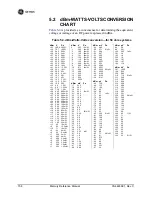
5.1
INSTALLATION PLANNING
This section provides tips for selecting an appropriate site, choosing an
antenna system, and reducing the chance of harmful interference.
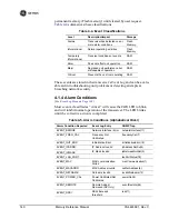
5.1.1 General Requirements
There are three main requirements for installing a transceiver—ade-
quate and stable primary power, a good antenna system, and the correct
interface between the transceiver and the data device.
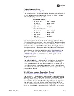
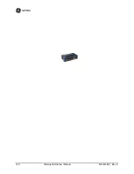
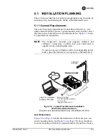
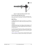
Figure 5-1
shows
a typical Remote installation.
NOTE:
The transceiver’s network port supports 10BaseT and
100BaseT connections. Confirm that your hub/switch is
capable of auto-switching data rates.
To prevent excessive Ethernet traffic from degrading perfor-
mance, place the transceiver in a segment, or behind routers.
Invisible place holder
Figure 5-1. Typical Fixed Remote Installation
With a Directional Antenna
(Connect user data equipment to any compatible LAN Port)
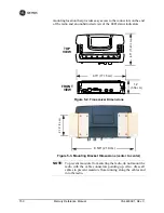
Unit Dimensions
Figure 5-2 on Page 150
shows the dimensions of the transceiver case
and its mounting holes, and
Figure 5-3 on Page 150
shows the dimen-
sions for mounting with factory-supplied brackets. If possible, choose a
POWER SUPPLY
13.8 VDC @ 580 mA (Max.)
(10.5–30 Vdc)
Negative Ground Only
COMPUTER RUNNING
TERMINAL PROGRAM
TRANSCEIVER
LOW
-LOSS FEEDLINE
ANTENNA
SYSTEM
Network
Summary of Contents for MDS Mercury Series
Page 2: ......
Page 10: ...2 Mercury Reference Manual 05 4446A01 Rev C ...
Page 28: ...20 Mercury Reference Manual 05 4446A01 Rev C ...
Page 36: ...28 Mercury Reference Manual 05 4446A01 Rev C ...
Page 140: ...132 Mercury Reference Manual 05 4446A01 Rev C ...
Page 142: ...134 Mercury Reference Manual 05 4446A01 Rev C ...
Page 156: ...148 Mercury Reference Manual 05 4446A01 Rev C ...
Page 168: ...160 Mercury Reference Manual 05 4446A01 Rev C ...
Page 184: ...176 Mercury Reference Manual 05 4446A01 Rev C ...
Page 194: ...I 10 Mercury Reference Manual 05 4446A01 Rev C ...


