


12
Mercury Reference Manual
05-4446A01, Rev. C
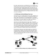
1.3.7 Upgrading Older Wireless Network with Serial
Interfaces
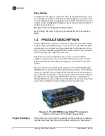
Millions of wireless data products have been installed in the last two
decades for licensed and license-free operation, many of them manufac-
tured by GE MDS. There are several ways that these systems can benefit
from incorporating Mercury
equipment. The chief advantages are inter-
face flexibility (serial and Ethernet in one unit), and higher data
throughput. By taking advantage of its built-in serial and Ethernet inter-
faces, the transceiver is well suited to replace leased lines, dial-up lines,
or existing 900 MHz “multiple address” data transceivers.
Replacing Legacy Wireless Products
In most cases, legacy radio transceivers supporting serial-interface
equipment can be replaced with Mercury transceivers. Legacy equip-
ment can be connected to the transceiver through the
COM1
port with a
DB-25 to DB-9 cable wired for EIA-232 signaling. The
COM1
port acts
as a Data Communications Equipment (DCE) port.
NOTE:
Several previous GE MDS-brand products had non-standard
signal lines on their interface connectors (for example, to
control sleep functions and alarm lines). These special func-
tions are not provided nor supported by the Mercury trans-
ceiver. Consult equipment manuals for complete pinout
information.
1.4
NETWORK DESIGN
CONSIDERATIONS
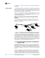
1.4.1 Extending Network Coverage with Repeaters
What is a Repeater System?
A repeater works by re-transmitting data from outlying remote sites to
the Access Point, and vice-versa. It introduces some additional
end-to-end transmission delay but provides longer-range connectivity.
In some geographical areas, obstacles can make communications diffi-
cult. These obstacles are commonly large buildings, hills, or dense
foliage. These obstacles can often be overcome with a repeater station.
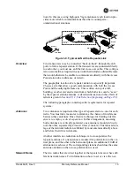
Option 1—Using two transceivers to form a repeater station
(back-to-back repeater)
Although the range between fixed transceivers can be up to 40 km (25
miles) over favorable terrain, it is possible to extend the range consider-
ably by connecting two units together at one site in a “back-to-back”
fashion, creating repeater as shown in
Figure 1-9
. Use this arrangement
whenever the objective is to utilize the maximum range between sta-
Summary of Contents for MDS Mercury Series
Page 2: ......
Page 10: ...2 Mercury Reference Manual 05 4446A01 Rev C ...
Page 28: ...20 Mercury Reference Manual 05 4446A01 Rev C ...
Page 36: ...28 Mercury Reference Manual 05 4446A01 Rev C ...
Page 140: ...132 Mercury Reference Manual 05 4446A01 Rev C ...
Page 142: ...134 Mercury Reference Manual 05 4446A01 Rev C ...
Page 156: ...148 Mercury Reference Manual 05 4446A01 Rev C ...
Page 168: ...160 Mercury Reference Manual 05 4446A01 Rev C ...
Page 184: ...176 Mercury Reference Manual 05 4446A01 Rev C ...
Page 194: ...I 10 Mercury Reference Manual 05 4446A01 Rev C ...


