05-4446A01, Rev. C
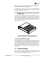
Mercury Reference Manual
13
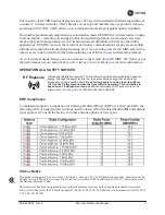
tions. In this case, using high-gain Yagi antennas at each location pro-
vides more reliable communications than their counterparts—
omnidirectional antennas.
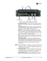
Invisible place holder
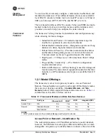
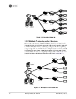
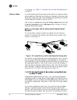
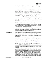
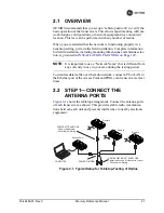
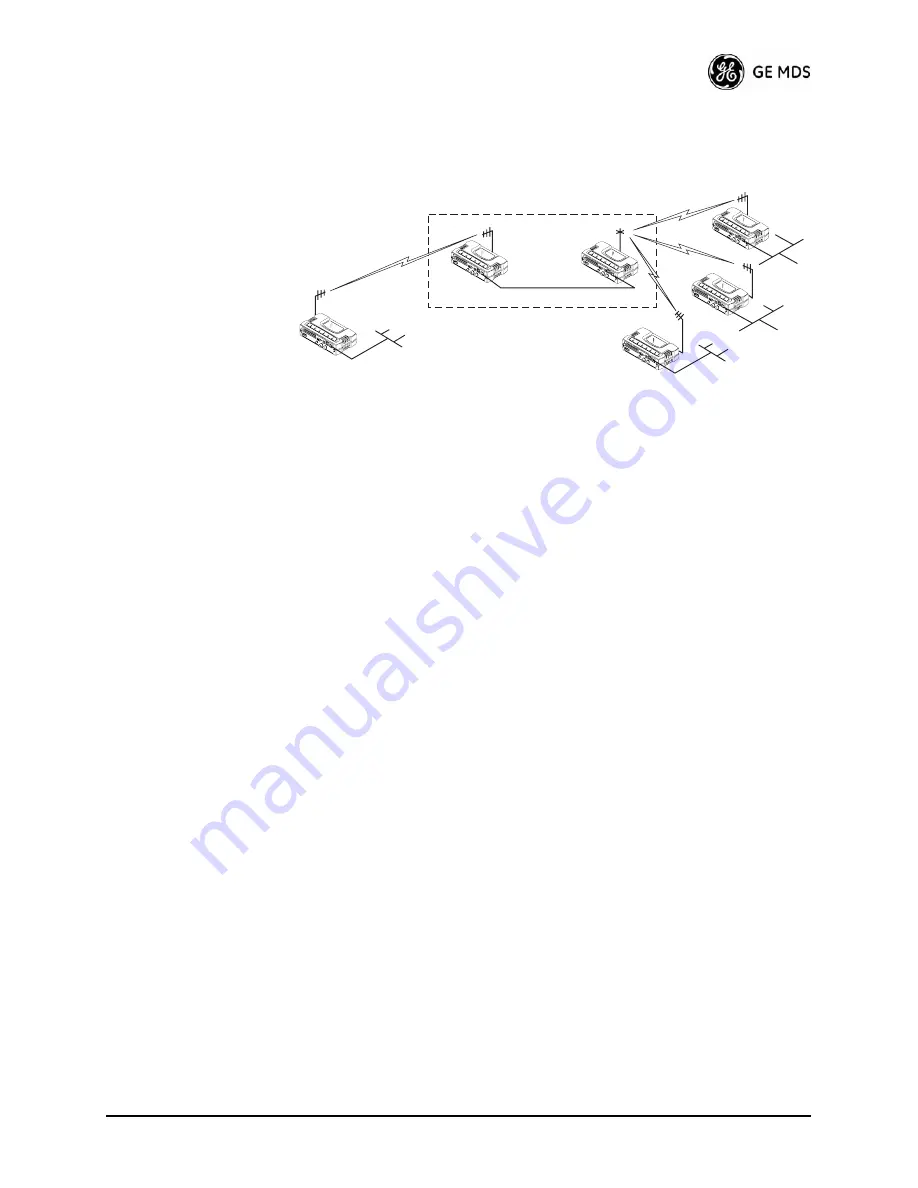
Figure 1-9. Typical LAN with a Repeater Link
Overview
Two transceivers may be connected “back-to-back” through the
LAN
ports to form a repeater station. If the transceivers are connected directly
to each other, you must use an Ethernet cross-over cable. This configu-
ration is sometimes required in a network that includes a distant Remote
that would otherwise be unable to communicate directly with the Access
Point station due to distance or terrain.
The geographic location of a repeater station is especially important.
Choose a site that allows good communication with
both
the Access
Point and the outlying Remote site. This is often on top of a hill,
building, or other elevated terrain from which both sites can be “seen”
by the repeater station antennas. A detailed discussion on the effects of
terrain is given in
Section 5.1.2,
Site Selection (beginning on Page 151)
.
The following paragraphs contain specific requirements for repeater
systems.
Antennas
Two antennas are required at this type of repeater station—one for each
radio. You must take measures to minimize the chance of interference
between these antennas. One effective technique for limiting interfer-
ence is to employ
vertical separation
. In this arrangement, assuming
both antennas are vertically polarized, one antenna is mounted
directly
over the other, separated by at least 10 feet (3 meters). This takes advan-
tage of the minimal radiation exhibited by most antennas directly above
and below their driven elements.
Another interference reduction technique is to cross-polarize the
repeater antennas. If one antenna is mounted for polarization in the ver-
tical plane, and the other in the horizontal plane, an additional 20 dB of
attenuation is achieved. The corresponding stations should use the same
antenna orientation when cross-polarization is used.
Network Name
The two radios that are wired together at the repeater site
must
have dif-
ferent network names. For information on how to set or view the net-
Remote
Remote
Remote
Remote
Access
Point
Access
Point
LAN/WAN
REPEATER
Crossover Cable
LAN
LAN
LAN
Ethernet
POINT
-TO-POINT
LINK
Summary of Contents for MDS Mercury Series
Page 2: ......
Page 10: ...2 Mercury Reference Manual 05 4446A01 Rev C ...
Page 28: ...20 Mercury Reference Manual 05 4446A01 Rev C ...
Page 36: ...28 Mercury Reference Manual 05 4446A01 Rev C ...
Page 140: ...132 Mercury Reference Manual 05 4446A01 Rev C ...
Page 142: ...134 Mercury Reference Manual 05 4446A01 Rev C ...
Page 156: ...148 Mercury Reference Manual 05 4446A01 Rev C ...
Page 168: ...160 Mercury Reference Manual 05 4446A01 Rev C ...
Page 184: ...176 Mercury Reference Manual 05 4446A01 Rev C ...
Page 194: ...I 10 Mercury Reference Manual 05 4446A01 Rev C ...


