background image

RCL220_manual_v3-draft.doc 

05-XXXXA01 Version 3 Draft 

Page 25 of 79 

9/20/2016 

DEVICE MODEL=220 REMOTE 
DEVICE SER=<serial number printed on silver label of radio> 
 
If any of these parameters are incorrect, you must correct them.  The model and serial number 
require factory or engineer login. 


Frequencies are typically set by the OCU or LCU proper, but you can set J block frequencies with 
the ENGFREQ command, e.g. ENGFREQ BFREQ1=221.96625 MFREQ1=220.96625. 
 
You can verify you are running the intended firmware with the VER command: 
 

Summary of Contents for MDS RCL220

Page 1: ...RCL220_manual_v3 draft doc 05 XXXXA01 Version 3 Draft Page 1 of 79 9 20 2016 GE MDS RCL220 Manual P N 05 XXXXA01 Version 3 ...

Page 2: ...t 16 3 Packaged or OEM Radio Command Line 17 3 1 Common Setup Tasks 17 3 1 1 Key the Transmitter for Test Purposes 17 3 1 2 Upgrade firmware on Packaged Radio Module or OEM Radio Module outside OCU 17 3 2 Packaged or OEM Radio Command Reference 30 3 2 1 ALARM 30 3 2 2 AUTH 30 3 2 3 COM1 32 3 2 4 COM2 33 3 2 5 CONFIG 35 3 2 6 DEVICE 35 3 2 7 ENCRYPT 37 3 2 8 GPS 37 3 2 9 HELP 38 3 2 10 LOG 38 3 2 1...

Page 3: ...XXA01 Version 3 Draft Page 3 of 79 9 20 2016 4 3 5 LCU AP Statistics Logging Menus 66 4 3 6 Repeater AP Statistics Logging Menus 68 4 3 7 Device Information Menu 70 4 3 8 Maintenance Tools Menu 72 5 Troubleshooting 77 6 Change Log 79 ...

Page 4: ...cautions such as touching a bare metal object to dissipate body charge prior to touching components or connecting disconnecting cables 1 3 FCC Approval Notice This device is offered as a licensed transmitter per FCC Parts 80 90 and 95 It is approved for use under the following conditions Changes or modifications not expressly approved by the party responsible for compliance will void the user s au...

Page 5: ...CU Used for Repeater entraNET 220 OEM Radio Module 1 0 0 entraNET 220 Packaged Radio Module 0 1 3 Access Point 0 1 1 Note that additional information vital to Phase V operation is given in SHL 028 The MDS entraNET 220 Phase V Primer Block diagrams for each unit are shown in the following figures Mounting Plate eNET 220 AP eNET 220 Packaged Radio Module PRM Transmitter eNET 220 Packaged Radio Modul...

Page 6: ...io Module ORM RCL Vendor OCU Controller COM2 Figure 2 entraNET 220 OCU Unit Block Diagram eNET 220 Packaged Radio Module PRM GPS Timing Receiver 1 PPS Position RCL Vendor LCU Controller COM2 RS 232 or 422 COM1 eNET 220 AP Position Diag COM1 COM2 LAN COM3 Figure 3 entraNET 220 LCU Unit Block Diagram ...

Page 7: ... 79 9 20 2016 2 1 Access Point This unit is used in the repeater and must also fit within the enclosure used at the LCU Photos and mechanical dimensions of this unit appear below Figure 4 Access Point Figure 5 Access Point Top View Figure 6 Access Point Front View ...

Page 8: ...al_v3 draft doc 05 XXXXA01 Version 3 Draft Page 8 of 79 9 20 2016 Figure 7 Access Point Bottom View Figure 8 Access Point Side View Figure 9 Mounting Bracket Can be used with Access Point or Packaged Radio Module ...

Page 9: ...eet2 pdf for information on our 03 4758A03 breakout kit for the Access Point and Packaged Radio Module DB 25 Pin Signal Direction WRT MDS Equipment 1 COM3_DCD Input 2 COM2_TXD Input 3 COM2_RXD Output 4 COM2_RTS Input 5 COM2_CTS Output 6 COM3_TXD Output 7 GND Input Output 8 COM2_DCD Output 9 COM3_CTS Input 10 COM3_RTS Output 11 COM3_DTR Output 12 COM3_RXD Input 13 GND Input Output 14 ETH_TX_H Outpu...

Page 10: ...e input to the radio to less than 30 Volts should be employed Pin Signal Name Direction with respect to MDS Equipment Description 1 L PWR Input 10 to 30 VDC input 125 mA at 13 8 VDC 2 I GROUND Input Power return 2 2 entraNET 220 OEM Radio Module This unit is used in each OCU It is a two board solution as shown below that mates with RCL vendor OCU hardware Mechanical diagrams are provided below as ...

Page 11: ...RCL220_manual_v3 draft doc 05 XXXXA01 Version 3 Draft Page 11 of 79 9 20 2016 Figure 11 entraNET 220 OEM Radio Module Top Shield View Figure 12 entraNET 220 OEM Radio Module End View ...

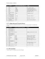
Page 12: ...T 220 OEM Radio Module Bottom View Figure 14 entraNET 220 OEM Radio Module Side View with PEM detail 2 2 1 J1 Ribbon Cable Connector Pinout The J1 Connector is a Samtec STMM 108 02 T D SM K TR The mating connector is a Samtec TCSD 08 D xx xx 01 F N J1 is the main interface to the OEM Radio Module ...

Page 13: ...ed 2 2 2 J4 Board Mount Connector Pinout The J4 Connector is a SAMTEC RSM 110 02 L D TR J4 is not typically populated on the OEM Radio Module Pin Function Direction WRT MDS Equipment Notes 1 Not Connected 2 Not Connected 3 Not Connected 4 Not Connected 5 IO3 Input ALARM_IN Active Low 0 to 5 V 6 Not Connected 7 Not Connected 8 Not Connected 9 GROUND Input Return for VIN and signals 10 TXD Input Ser...

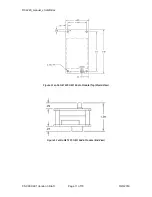
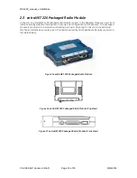
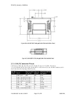
Page 14: ...ical hardware so that only one configuration must be spared The packaged module is provided in a cast aluminum housing as shown Mounting for this unit is shown below Mechanical dimensions are also given The interfaces used by Packaged Radio Modules are listed in the tables below Figure 15 entraNET 220 Packaged Radio Module Figure 16 entraNET 220 Packaged Radio Module Top View Figure 17 entraNET 22...

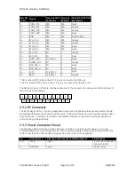
Page 15: ... of the PRM Please see TD_RCL_Adapter_Board_Instruction_Sheet2 pdf for information on our 03 4758A03 breakout kit for the Access Point and Packaged Radio Module New DB 25 Pin Signal Previous PRM Connector Previous PRM Pin Direction WRT MDS Equipment 1 COM3_DCD N A N A Input 2 COM2_TXD TXD J3 COM2 6 Input 3 COM2_RXD RXD J3 COM2 5 Output 4 COM2_RTS TXD J3 COM2 8 Input 5 COM2_CTS J3 COM2 7 Output 6 C...

Page 16: ...r is female and the orientation of the connector as looking into the front panel of the unit is as shown below 12 11 10 9 8 7 6 5 4 3 2 1 24 23 22 21 20 19 18 17 16 15 14 13 25 2 3 2 RF Connector The RF connector is TNC Lightning suppression such as a Polyphaser IS B50 series protector should be employed between the antenna and the radio The body of the protector should be well grounded to earth g...

Page 17: ...mission and enter with RADIO AUXTX frequency 4 Enter RADIO TXKEY ON 5 When finished enter RADIO TXKEY OFF The test transmission is modulated not CW and is a repetitive data pattern over the air 3 1 2 Upgrade firmware on Packaged Radio Module or OEM Radio Module outside OCU 1 Log in to the radio on its COM2 console 2 Put the radio into calibration mode by entering RADIO MODE CAL 3 Set the radio to ...

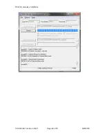
Page 18: ... s current configuration and restore it after the upgrade This is needed when jumping several revisions of the firmware since some parameter locations could have changed setting parameters to their defaults upon upgrade 13 Optionally you may click Get Configuration to download the radio s settings to a text file you specify by clicking the button on the same line 14 Optionally you may click Set Co...

Page 19: ...RCL220_manual_v3 draft doc 05 XXXXA01 Version 3 Draft Page 19 of 79 9 20 2016 ...

Page 20: ...RCL220_manual_v3 draft doc 05 XXXXA01 Version 3 Draft Page 20 of 79 9 20 2016 ...

Page 21: ...RCL220_manual_v3 draft doc 05 XXXXA01 Version 3 Draft Page 21 of 79 9 20 2016 ...

Page 22: ...RCL220_manual_v3 draft doc 05 XXXXA01 Version 3 Draft Page 22 of 79 9 20 2016 ...

Page 23: ...RCL220_manual_v3 draft doc 05 XXXXA01 Version 3 Draft Page 23 of 79 9 20 2016 ...

Page 24: ...rocessor has to perform an internal upgrade of the DSP and MCU This takes a few minutes when first rebooting to the new firmware during which the command line will be non responsive Sometimes the Remote Upgrade Utility never reports that the radio has booted to the new firmware even though it has so you can also check this by logging into the radio with your terminal program In this case it is pro...

Page 25: ... If any of these parameters are incorrect you must correct them The model and serial number require factory or engineer login Frequencies are typically set by the OCU or LCU proper but you can set J block frequencies with the ENGFREQ command e g ENGFREQ BFREQ1 221 96625 MFREQ1 220 96625 You can verify you are running the intended firmware with the VER command ...

Page 26: ... radios on the bench To do this test you will require two PRMs power supplies serial connectivity RF cables and RF attenuators to join the radios antenna ports and the Poller and Responder utilities to simulate the LCU and OCU for sending and receiving messages BEWARE Do not simply cable the two radios together or you may damage one or both of the receivers Use at least 90 dB of attenuation betwee...

Page 27: ...2 Set the Polling device LCR to data mode with COM2 DEFAULT DATA MODE DATA Note after this point when you power cycle the radio it will come up into data mode so that it is ready to poll To regain the console type and then hit Enter 3 Set the Responding device OCR as shown below ...

Page 28: ...a mode with COM2 DEFAULT DATA MODE DATA Note after this point when you power cycle the radio it will come up into data mode so that it is ready to poll To regain the console type and then hit Enter 5 Set the Poller application to match your Polling radio 6 Set the Responder application to match your Responding radio ...

Page 29: ...RCL220_manual_v3 draft doc 05 XXXXA01 Version 3 Draft Page 29 of 79 9 20 2016 7 Hit Start on the Responder if necessary 8 Hit Start on the Poller if necessary 9 Observe operation ...

Page 30: ...ex Bits Codes It lists the hex bit codes for the current alarm condition by class For each specific event that causes an alarm the corresponding bit is set Event bits are TBD 3 2 2 AUTH Usage AUTH KEY key PRODUCT product TYPE type COM2 com2 ETHERNET ethernet MANAGEMENT management SERIAL serial DON T_CARE dont_care RUN run ENDPOINTS endpoints MOBILITY mobility FACTDEF factdef FSET fset MAINTBAY mai...

Page 31: ...BLED Ethernet disabled ENABLED Ethernet enabled MANAGEMENT management Read Only for all users listed above DISABLED Network management disabled ENABLED Network management enabled SERIAL serial Read Only for all users listed above DISABLED Serial payload disabled ENABLED Serial payload enabled DONT_CARE dont_care Read Only for all users listed above 0 X don t care 1 X don t care RUN run Read Only f...

Page 32: ...pany features set 3 4 Company features set 4 5 Company features set 5 6 Company features set 6 MAINTBAY maintbay Read Only for all users listed above Maintenance Bay serve OTA reprogramming DISABLED Do not allow Maintenance Bay Mode ENABLED Allow Maintenance Bay Mode CMD cmd If set to 0 the command executes normally If cmd is set to 1 the command reports all settings in a format that may be copied...

Page 33: ... 7N1 7 char bits no parity 1 stop bit 7N2 7 char bits no parity 2 stop bits 7O1 7 char bits odd parity 1 stop bit 7O2 7 char bits odd parity 2 stop bits 7E1 7 char bits even parity 1 stop bit 7E2 7 char bits even parity 2 stop bits 8N1 8 char bits no parity 1 stop bit 8N2 8 char bits no parity 2 stop bits 8O1 8 char bits odd parity 1 stop bit 8O2 8 char bits odd parity 2 stop bits 8E1 8 char bits ...

Page 34: ...onsecutive characters to COM1 with at least 10 mSecs between them CONSOLE Com2 in Command line mode DATA Com2 defaults to Basic Serial Protocol mode BSP Com2 in BSP data mode INT_LOOP Com2 in Internal Loopback mode EXT_LOOP Com2 in External Loopback mode SURVEY Com2 in Survey BSP mode SNIFFER Com2 in Sniffer BSP mode Repeater BAUD baud Read Write Set display baud rate setting 1200 1200 bps 2400 24...

Page 35: ... Duplex HALF Half Duplex CMD cmd If set to 0 the command executes normally If cmd is set to 1 the command reports all settings in a format that may be copied into a configuration script 3 2 5 CONFIG Usage CONFIG SHOW SAVE Description Save Display the current configuration The output is in a format that may be copied back into the command line in order to set the configuration NOTE CMD 1 command no...

Page 36: ...ay product name Allowable length 1 20 characters REV Read Only Set display software ID Allowable length 1 15 characters OWNER owner Read Write Set display owner information string Owner can program any information as 1 string Allowable length 1 30 characters TYPE Read Write starting from Adminstrator Select device to function as normal Remote or Repeater unit REMOTE Normal Remote Unit REPEATER Rep...

Page 37: ...E CMD 1 short form response command is supported Access Level Administrator Optional Arguments LCU lcu Read Write Set display for LCU encryption index Acceptable value range 0 31 OCUA ocua Read Write Set display for OCUA encryption index Acceptable value range 0 31 OCUB ocub Read Write Set display for OCUB encryption index Acceptable value range 0 31 CMD cmd If set to 0 the command executes normal...

Page 38: ...cmd is set to 1 the command reports all settings in a format that may be copied into a configuration script 3 2 9 HELP Usage HELP Description List commands supported for the current user login level NOTE CMD 1 command not supported Access Level Logged Out User Optional Arguments none 3 2 10 LOG Usage LOG CLEAR SHOW TOTAL CMD cmd Description Set display the event log information Displays the number...

Page 39: ... format that may be copied into a configuration script 3 2 11 LOGIN Usage LOGIN Description Secure Login At prompt enter case sensitive username ADMIN FACT ENGR At prompt enter case sensitive password can be up to 8 characters NOTE CMD 1 command not supported Access Level Logged Out User Optional Arguments none 3 2 12 LOGOUT Usage LOGOUT Description Log out NOTE CMD 1 command not supported Access ...

Page 40: ...age reprogram statusVERIFY verify Write Only for all users starting at Administrator Select one or all images to perform checksum verification ALL All images BOOT Bootloader Image APP1 App 1 Image APP2 App 2 Image DSP1 DSP 1 Image DSP2 DSP 2 Image MCU1 MCU 1 Image MCU2 MCU 2 Image MODE mode Read Write for all users listed above COM1_RECEIVE Accept reprogramming over the local serial port RADIO_REC...

Page 41: ...2 MFREQ2 mfreq2 BFREQ3 bfreq3 MFREQ3 BFREQ4 bfreq4 MFREQ4 AUXTX auxtx AUXRX auxrx TIMESLOT timeslot YARDRSSI integer TXSTART number SYNCTIMEOUT synctimeout GROUPTIMEOUT grouptimeout CMD cmd Description Set display the radio configuration and status NOTE CMD 1 short form response command is supported Access Level Administrator Optional Arguments COMMITCHANS Update ROR channels 3 4 with last RCL Syn...

Page 42: ...arting at Administrator Current Secondary Radio B Repeater Frequency Acceptable value range 216 222 MHz Channels MFREQ2 XXX XXXXXX Read Write for all users starting at Administrator Current Secondary Radio M Mobile Frequency Acceptable value range 216 222 MHz Channels BFREQ3 XXX XXXXXX Read Write for all users starting at Administrator Current 3rd Radio B Repeater Frequency Acceptable value range ...

Page 43: ...ze Acceptable value range 216 222 MHz Channels 1Hz frequency step AUXRX XXX XXXXXX Read Only Auxillary Receive Frequency Value range 216 222 MHz 1Hz frequency step size Acceptable value range 216 222 MHz Channels 1Hz frequency step TXSTART txstart Read Write for all users starting at Administrator Seconds to timeout before transmit at boot up If set to 0 transmit will never start Acceptable value ...

Page 44: ...ly for all users starting at Administrator Other Image 3 2 17 REPEATERS Usage REPEATERS CLEAR CHANMASK chanmask LASTBFREQ3 lastbfreq3 LASTMFREQ3 lastbfreq3 LASTBFREQ4 lastbfreq4 LASTMFREQ4 lastmfreq4 Description Access Level Administrator Optional Arguments CLEAR CHANMASK chanmask Repeater channel N availability chanmask is a bitmap which sets the accessibility of four channels Bit zero through th...

Page 45: ...Usage SLEEP MODE mode WAKE wake DTRSENSE dtrsense HANGTIME hangtime NOW now CMD cmd Description Set display the configuration of the radio s low power mode NOTE CMD 1 short form response command is supported Access Level Administrator Optional Arguments MODE mode Write Only for all users starting at Administrator This selects one of the low power operating modes the remote will operate under NONE ...

Page 46: ...ATS Usage STATS ALL RADIO COM1 COM2 RESET Description Radio statistics If device RADIO COM1 COM2 ETH is omitted all statistics are displayed NOTE CMD 1 command not supported Access Level Administrator Optional Arguments ALL Read Only for all users listed above Get all statistics RADIO Read Only for all users listed above Get radio packet statistics TBD COM1 Read Only for all users listed above Get...

Page 47: ...e length 1 8 characters DSREV1 Read Only for all users listed above Display ROR radio DSP software image 1 version Allowable length 1 8 characters MSREV1 Read Only for all users listed above Display ROR radio MCU software image 1 version Allowable length 1 8 characters SWID2 Read Only for all users listed above Current Image 2 Software ID text 06 nnnnAnn Allowable length 1 10 characters SREV2 Read...

Page 48: ...isted above This command is used to determine whether the current Event list properties need to be upgraded or not LOG Read Only for all users listed above This command is used to determine whether the current Log format needs to be upgraded or not HREV Read Only OIB Board Hardware Revision Allowable length 1 8 characters XHREV Read Only OEM Radio Board Hardware Revision Allowable length 1 8 chara...

Page 49: ...e for all users starting at Administrator Minimum in yard RSSI value in dBm Acceptable value range 8bits integer 128 to 127 RSSI rssi Read Only Current yard RSSI value in dBm Acceptable value range 8bits integer 128 to 127 ID id Read Only Current yard ID Acceptable value range 8bits integer 128 to 127 SHAPE shape Read Only ELLIPSE Ellipse ROT rot Read Only Yard Shape Rotate Degrees Acceptable valu...

Page 50: ...on script 4 Access Point Menu Interface The COM1 console of the access point can be accessed using a serial terminal emulator program such as HyperTerminal Putty or ucon The default settings are baud rate 19200 no parity 8 data bits and 1 stop bit The pins for this port are listed in section 2 1 2 In some cases this port is used for binary data and is not escapable to the login prompt In this case...

Page 51: ...u is the entryway to all customer definable features The radio Device Name appears at the top of this and all other screens as a reminder of the unit that is being interrogated Starting Information Screen G Main Menu Availability Repeater and LCU Parameter Description Values A Starting Information Screen Select this item to return to the Starting Information Screen ...

Page 52: ...ation Tools to configure the transceiver security services E Statistics Logging Tools to measure the radio and data layer network performance F Device Information Top level customer specific and definable parameters such as the date time console baud rate and device name information G Maintenance Tools Tools for upgrading and selecting firmware images and configuration files and applying Authoriza...

Page 53: ...address netmask and gateway addresses 4 3 1 1 IP Configuration Menu The unit uses a local IP address to support remote management and backhaul services CAUTION Changes to any of the following parameters while communicating over the network LAN or over the air may cause a loss of communication with the unit being configured Communication will need to be re established using the new IP address Main ...

Page 54: ...y valid IP address that will be unique within the network Any valid IP address 192 168 1 1 B IP Netmask The IPv4 local subnet mask X X X X X 1 254 255 255 0 0 C IP Gateway The IPv4 gateway used to access nodes outside of the unit s subnet This field is unnecessary if all devices are on the same subnet X X X X X 1 254 0 0 0 0 4 3 2 System Configuration Menu Main menu C System Configuration Availabi...

Page 55: ...es A System Mode Toggle between the operating mode for this AP LCU for use aboard a locomotive with attachment to a GPS receiver and an MDS entraNET 220 Packaged Radio Module Maintenance Bay for use in a Kiosk for OCU Radio upgrade and test or Repeater for use in a repeater with attachment to one transmitter and two receiver Packaged Radio Modules LCU Repeater Maintenance Bay Repeater B External P...

Page 56: ...ogging of BSP messages to remote server enabled disabled disabled B BSP Log Server IP address of BSP message server Any valid IP address 0 0 0 0 C BSP Log Server Port IP port for BSP message server 0 65535 0 4 3 2 2 Frequency Configuration Menu Main menu C System Configuration E Frequency Configuration Availability Repeater only ...

Page 57: ...ncy on Channel 2 216 006250 221 993750 221 118750 D B Frequency 3 The Base Frequency on Channel 3 216 006250 221 993750 0 E B Frequency 4 The Base Frequency on Channel 4 216 006250 221 993750 0 F Aux Tx Frequency The Auxiliary Transmit Frequency 216 006250 222 000000 223 600000 K Aux Rx Frequency The Auxiliary Receive Frequency 216 006250 222 000000 223 600000 4 3 2 3 Backhaul Configuration Menu M...

Page 58: ...g RSSI Limit Limit used when determining which repeater to route the next message to Normally messages for a given RCL unit LCU OCUA or OCUB are sent via the repeater that heard the unit the strongest during the last second If the RSSI limit is set to a value besides 120 and 0 the routing logic will instead use the repeater with the strongest RSSI less than the limit 128 0 0 4 3 2 4 Yard Configura...

Page 59: ...049706 8 757006443 10 827285137 13 233631341 16 000705871 1 000000000 F Yard Y Diameter The Y diameter of the yard in miles 1 000000000 1 005013881 1 038892703 1 128915711 1 301690951 1 583418004 2 000000000 2 577107281 3 340218650 4 314650297 5 525577218 6 998049706 8 757006443 10 827285137 13 233631341 16 000705871 1 000000000 4 3 2 5 Slot Group Configuration Menu The repeater system employs 15 ...

Page 60: ...oup X enabled disabled enabled 4 3 3 Security Configuration Menu Main menu D Security Configuration Availability Repeater and LCU Parameter Description Values A HTTP Access Allows remote access through HTTP a Web browser on Port 80 enabled disabled enabled B Telnet Access Allows remote access through Telnet sessions on Port 23 enabled disabled enabled ...

Page 61: ...unit Used at log in via the COM1 Port Telnet session and Web browser session 4 3 3 1 User Passwords Menu Main menu D Security Configuration D User Passwords Availability Repeater and LCU Parameter Description Values A Change Admin Password Change Admin Password Passwords are case sensitive can be mixed case 1 8 alphanumeric characters admin B Change Guest Password Change Guest Password Passwords a...

Page 62: ...u C LCR Status The LCR Status menu D Current Yard Status The Current Yard Status menu Main menu E Statistics Logging Availability Repeater version Parameter Description Values A Ethernet Packet Statistics The Ethernet Packet Statistics menu B Event Log The Event Log menu C RSSI Status The RSSI Status menu D Routing Status The Routing Status menu E Slot Group Allocation The Slot Group Allocation me...

Page 63: ...ter and LCU Parameter Description Values Packets Received Packets received through the Ethernet port of the transceiver 0 Packets Sent Packets send through the Ethernet port of the transceiver 0 Bytes Received Data bytes received by this radio 0 Bytes Sent Data bytes sent by this radio 0 Packets Dropped Received packets dropped from a lack of buffers 0 Receive Errors Packets discarded after more t...

Page 64: ...he manually set time and date clock Main menu E Statistics Logging B Event Log Availability Repeater and LCU Parameter Description Values A Current Alarms Lists events that have caused the unit to enter the alarmed state B View Event Log Lists events stored in the current log C Clear Event Log Purges the log of all stored events D Send Event Log Initiates TFTP transfer of the Event Log in a plain ...

Page 65: ...LOG server as they occur Use this field to enter the IP address of this server Any valid IP address 127 0 0 1 4 3 4 2 1 Current Alarms Menu Main menu E Statistics Logging B Event Log A Current Alarms Availability Repeater and LCU 4 3 4 2 2 View Event Log Menu Main menu E Statistics Logging B Event Log B View Event Log Availability Repeater and LCU ...

Page 66: ...mber of Satellites Displays the number of satellites in view of the GPS receiver 0 12 0 GPS Latitude Displays positive numbers for North Latitude and negative numbers for South Latitude 90 to 90 0 GPS Longitude Displays positive numbers for West Longitude and negative numbers for East Longitude 180 to 180 0 Number of Yards The LCU Radio acquires information about yards over the air This field disp...

Page 67: ... the yard center 90 0000000 90 0000000 0 0000000 D Yard Rotation The degrees of rotation about the yard center 0 000 5 625 11 250 16 875 22 500 28 125 33 750 39 375 45 000 50 625 56 250 61 875 67 500 73 125 78 750 84 375 0 000 E Yard X Diameter The X diameter of the yard in miles 1 000000000 1 005013881 1 038892703 1 128915711 1 301690951 1 583418004 2 000000000 2 577107281 3 340218650 4 314650297...

Page 68: ... AP Statistics Logging Menus 4 3 6 1 RSSI Status Menu This screen displays the received signal strength in dBm on the main and diversity receiver of the Repeater for each RCL unit LCU OCUA and OCUB in each repeater time slot 0 14 Main menu E Statistics Logging C RSSI Status Availability Repeater only 4 3 6 2 Routing Status Menu This screen displays the favored route Repeater IP address and Receive...

Page 69: ... time slot for each RCL unit LCU OCUA OCUB within coordination Main menu E Statistics Logging E Slot Group Allocation Availability Repeater only 4 3 6 4 RCS Member Repeaters Menu This screen shows the IP addresses and time last heard for each Repeater within the community Main menu E Statistics Logging F RCS Member Repeaters Availability Repeater only ...

Page 70: ...aud Rate setting and customer specific parameters under the Device Names selection Main menu F Device Information Availability Repeater and LCU Parameter Description Values Model Model type of the connected unit MDS entraNET 220 Serial Number The serial number of the Access Point 0 9999999 Uptime The elapsed time since the last unit reboot A Date Current date being used for the transceiver logs cu...

Page 71: ...an Generic D Console Baud Rate Allows setting the console baud rate to match the connected terminal 1200 2400 4800 9600 19200 38400 57600 115200 19200 E Device Names The Device Name contact location and description fields for each unit can be used to record whatever communications specific information is useful to your organization the information appears on this screen only NOTE The date and time...

Page 72: ...ion of this product Any 40 char alphanumeric string Blank 4 3 8 Maintenance Tools Menu In the course of operating your network you may want to take advantage of product improvements and to read and archive the configuration of your individual transceivers The Maintenance Menu provides several tools to make this possible This section provides detailed information on how to use these services Key ma...

Page 73: ... Utility Diagnostic tool to test network connectivity D Authorization Codes Alter the radio capabilities by enabling the built in resources via purchased keys 4 3 8 1 Reprogramming Menu The AP has two copies of the firmware microprocessor code used for the operating system and applications One copy is active and the second one is standing by ready to be used Using the Reprogramming Menu you can up...

Page 74: ...e Verify Initiate integrity verification of the firmware file held in the unit 1 2 F Image Copy Copying the active firmware into the inactive image y n G Reboot Device Restart the unit Use this command to toggle between firmware images 1 2 Current Firmware Shows the current firmware revision level 0 0 0 4 3 8 2 Configuration Scripts Menu If you plan to have more than a few transceivers in your net...

Page 75: ...ASCII format May require a sub directory for example config eNET_220_Repeater txt Any 40 char alphanumeric string blank cfgscript txt C TFTP Timeout Time in seconds the TFTP server waits for a packet ACK acknowledgment from the unit before suspending the file transfer 10 120 30 D Retrieve File Initiate the file transfer of the configuration file from the TFTP server into the unit y n E Send File I...

Page 76: ...B Count Number of Ping packets to be sent 0 999999999 4 C Packet SIze Size in bytes of each Ping data packet 0 65535 32 D Ping Start sending PING packets to address shown on screen The process can be stopped at any time by pressing Ctrl C on the PC keyboard The screen then displays a detailed report of PING activity Press any key after viewing the results to return to this menu ...

Page 77: ...ti repeater coordination and Diversity Receiver use 5 Troubleshooting Here are some tips to help resolve issues when operating the RCL220 Symptom Possible Cause Radio is alarmed PWR LED is flashing Check the alarm list accessible from the Starting Information Screen Alarm GPS PPS Not Available Radio is not receiving a PPS Alarm GPS Signal Inverted Although a PPS has been detected it is in the ACTI...

Page 78: ...anual_v3 draft doc 05 XXXXA01 Version 3 Draft Page 78 of 79 9 20 2016 Alarm OTA Sync Lost The radio has lost over the air synchronization because it is no longer receiving wireless beacons from a packaged radio ...

Page 79: ...t doc 05 XXXXA01 Version 3 Draft Page 79 of 79 9 20 2016 6 Change Log Version Date Author Changes 1 12 31 2014 T Mayo Initial release for RCL220 2 01 07 2015 T Mayo Added reference to the DB 25 adapter kit instruction sheet ...

Reviews: