background image


MDS 05-7280A01, Rev. A 

MDS TransNEXT Technical Manual 

17


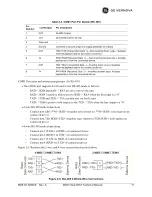
Table 2-3. COM1 Port Pin Details (RS-485) 

Pin  
Number 

Input/Output 

Pin Description 

OUT 

ALARM Output  

OUT 

DCD (Data Carrier Detect) 

Reserved 

-- 

Ground 

Connects to ground (negative supply potential) on chassis 

OUT 

TXD+/TXB (Transmitted Data +)

—Non-inverting driver output. Supplies 

received payload data to the connected device. 

IN 

RXD+/RXB (Received Data +) 

— Non-inverting receiver input. Accepts 

payload data from the connected device. 

OUT 

TXD-/TXA (Transmitted Data -)

—Inverting driver output. Supplies 

received payload data to the connected device. 

IN 

RXD-/RXA (Received Data -) 

— Inverting receiver input. Accepts 

payload data from the connected device. 


COM1 Port notes and wiring arrangements (for RS-485) 


The COM1 port supports 4-wire and 2-wire RS-485 mode as follows: 

-


RXD+ / RXB and RXD– / RXA are data sent 

into 

the unit


-


RXD+ / RXB is positive with respect to RXD– / RXA when the line input is a “0”


-


TXD+ / TXB and TXD– / TXA are data sent

 out 

by the unit


-


TXD+ / TXB is positive with respect to the TXD– / TXA when the line output is a “0”


2-wire RS-485 mode connections: 

-


Connect pins 5&6 (TXD+/RXD+) together and connect to (TXD+/RXD+) tied together on 
connected device


-


Connect pins 7&8 (RXD-/TXD-) together and connect to (TXD-/RXD-) tied together on 
connected device


4-wire RS-485 mode connections: 

-


Connect pin 5 (TXD+) to RXD+ of connected device


-


Connect pin 6 (RXD+) to TXD+ of connected device


-


Connect pin 7 (TXD-) to RXD- of connected device


-


Connect pin 8 (RXD-) to TXD- of connected device


Figure 2-5 illustrates the 2-wire and 4-wire connections described above. 


Figure 2-5. EIA-485 4-Wire/2-Wire Connections 

Summary of Contents for MDS TransNEXT NET9L

Page 1: ...MDS TransNEXT MDS TransNEXT Technical Manual Rev A December 2023 Technical Manual Technical Manual...

Page 2: ...W 21 SETTING BASIC PARAMETERS FIRST STEPS 21 3 0 DEVICE MANAGEMENT 22 3 1 USING THE WEB USER INTERFACE 22 3 2 USING THE COMMAND LINE INTERFACE CLI 28 DIFFERENCES BETWEEN USB SERIAL AND SSH 28 ESTABLIS...

Page 3: ...3 TECHNICAL SPECIFICATIONS 53 5 0 GLOSSARY OF TERMS AND ABBREVIATIONS 56 6 0 APPENDIX A ELECTRONIC INK DISPLAY 59 6 1 INTRODUCTION 59 6 2 STATUS PAGE 59 6 3 ANTENNA ALIGNMENT PAGE 59 6 4 SPECTRUM ANA...

Page 4: ...t the following website www fcc gov oet info documents bulletins Concentr d nergie partir d une antenne directionnelle peut poser un risque pour la sant humaine Ne pas permettre aux gens de se rapproc...

Page 5: ...ansNEXT Professional installation is required The installation site must conform to 15 247 RSS 247 Conducted and Radiated Power limits Proper feedline selection and or radio power setpoints must be se...

Page 6: ...ed in this list having a gain greater than the maximum gain indicated for that type are strictly prohibited for use with this device Cet appareil est conforme la Partie 15 des r glements de la FCC et...

Page 7: ...restricted based on applicable region specific regulatory constraints FCC IC IDs As of the printing date the following identifiers are assigned to the models listed below Model FCC ID IC ID NET9L E5MD...

Page 8: ...nate the environment and present a health risk due to hazardous substances contained within To avoid dissemination of these substances into our environment and to limit the demand on natural resources...

Page 9: ...ding a suitable degree of protection against deterioration of the equipment that would adversely affect its suitability for use in the hazardous locations area and to avoid USB C diagnostic port conne...

Page 10: ...sNET Lite model NXT9L Figure 1 2 Figure 1 3 TransNET Standard with Display model NXT9S Information on other GE MDS products can be found by visiting our website at www gemds com About This Manual This...

Page 11: ...echnical Manual 11 For example 1234567 Login admin NOTE The software commands and responses shown in this manual were obtained from a unit operating in a lab environment The information displayed may...

Page 12: ...may be easily mounted inside a NEMA enclosure for outdoor applications when required User Interface Multiple user interfaces are provided for configuration and monitoring of the unit These include US...

Page 13: ...e data from the outlying site is received at the licensed Remote site it is transferred to the licensed radio via a local cable connection and is then transmitted to the MAS Master station in the usua...

Page 14: ...and I O A latching 6 pin connector is used Figure 2 3 It is keyed and can only be inserted one way Pin 1 is GND Pin 5 is Vin Pins 2 4 and 6 are reserved for future I O capability Use Copper Conductors...

Page 15: ...ort As viewed from the outside the unit Table 2 1 ETH1 2 Pin Details Pin Function Pin Function 1 Transmit Data TX High 5 Unused 2 Transmit Data TX Low 6 Receive Data RX Low 3 Receive Data RX High 7 Un...

Page 16: ...even parity 2 stop bits 8 E 2 The tables on the following page provide pin descriptions for the COM data port in RS 232 mode and RS 485 modes respectively As viewed from the outside the unit Table 2...

Page 17: ...t notes and wiring arrangements for RS 485 The COM1 port supports 4 wire and 2 wire RS 485 mode as follows RXD RXB and RXD RXA are data sent into the unit RXD RXB is positive with respect to RXD RXA w...

Page 18: ...ils for connections made using this adapter WIRING CHART RJ 45 PIN FUNCTION DB9 PIN 1 DSR 6 2 DCD 1 3 DTR 4 4 GND 5 5 RXD 2 6 TXD 3 7 CTS 8 8 RTS 7 LED Button Panel The LEDs on the top of the unit pro...

Page 19: ...d 2 4 Grounding Considerations To minimize the chance of damage to the unit and its connected equipment a safety ground NEC Class 2 compliant is recommended which bonds the chassis antenna system s po...

Page 20: ...2 7 Figure 2 7 DIN Rail Attachment examples Pull down tab to release from rail 2 6 Antenna Planning and Installation Consideration must be taken to select appropriate antennas for optimal RF performan...

Page 21: ...Accessories Ancillary Items Item Description Part Number DC Power Plug 6 pin polarized Mates with power connector on the unit s case Screw terminals are provided for wires threaded locking screws to...

Page 22: ...r Interface UI or from the Command Line Interface CLI Either way requires two steps The first step is to use a user interface to add remove or alter a piece of configuration data The second step is to...

Page 23: ...me and a unique 10 character password printed on the unit Click the Login button Figure 3 2 Login Screen After successful login the initial web page is displayed Every page includes a banner section a...

Page 24: ...Radio Stats are associated with the operation of the radio itself This includes RSSI Output Power VSWR status Good Bad and link layer counts for Transmission and Reception The 3 boxes on the bottom r...

Page 25: ...crollbar on the right to the appropriate configuration group com1 radio etc Next find the specific attribute in the group to modify The attribute s current value is shown immediately to the right of t...

Page 26: ...entire network of TransNEXT remotes The operation relies on unacknowledged broadcast transmission with variable repeats Choose the transmission mode setting based on the characteristics of the connec...

Page 27: ...ed in reverse chronological order The log index is a relative indicator of time The most recent log has index number 0 and is shown first Each time you return to the Logging page the index is recalcul...

Page 28: ...n as a payload data port using a pre configured baud rate default is 115 2kbps To temporarily enter into command line mode on the payload port it is necessary to type the escape sequence SSH access us...

Page 29: ...progress Please press D to disconnect remote console user Login with the user name admin and default admin password for this unit Establishing Communication Serial Interface Follow these steps to conf...

Page 30: ...p Display serial payload history setup Disable hopping and enter radio setup mode show Show various system attributes uptime Radio uptime Individual commands have their own help Enter the command name...

Page 31: ...si Get last RSSI sample quit Exit radio setup mode app help app 1 2 Set active image app update Update app inactive image over Ymodem app copy Copy the active image to the inactive When working with t...

Page 32: ...Group Key Items controlled owner Owner name and message system System operating characteristics leds Reserved for future pushbtn Reserved for future display Settings associated with E ink display beha...

Page 33: ...0 0 unit_addr 4567 mode R ippl enabled off mode udp talk_on_vrc 1 listen_to_vrc 1 local_ip_port 30011 ip_peer_addr 192 168 1 1 ip_peer_port 30011 connection_timeout 0 keepAlive off dlink enabled on t...

Page 34: ...is specified as a decimal number Other radio attribute group settings behave differently For example radio mode is set by entering a quoted m x or r for master extension or remote respectively Failure...

Page 35: ...th other radio default settings 3 3 2 4 radio hoptime 7 or 28 This controls radio hop timing The item is a value corresponding to the hop time setting in milliseconds 7 and 28 are the only choices Def...

Page 36: ...s a Primary Extended Address specifying the primary radio with which this radio will attempt to synchronize and communicate Whenever the current radio attempts to establish sync it will limit its choi...

Page 37: ...is recommended and should only be changed if a conflict is detected This method helps minimize conflicts between radios 3 3 2 13 radio mode m or r or x The radio mode attribute sets the operating mode...

Page 38: ...m response of the device Display settings The Display attribute group contains settings associated with the optional E ink display Changing these items has no affect on a unit that is not equipped wit...

Page 39: ...is 192 168 1 254 COM1 settings The COM1 attribute group contains settings associated with serial payload data including settings for baud handshaking RS232 RS485 mode and embedded RTU simulator contr...

Page 40: ...lues are 0 to 65535 milliseconds Default is 0 Used when com1 device is cts key this command sets the amount of time in milliseconds that CTS remains present following transmission of the last characte...

Page 41: ...cfg get ippl enabled off mode udp talk_on_vrc 1 listen_to_vrc 1 local_ip_port 30011 ip_peer_addr 192 168 1 1 ip_peer_port 30011 connection_timeout 0 keepAlive off 3 3 8 1 ippl enabled on or off This a...

Page 42: ...gnostics transactions Default is off NOTE To address security concerns TransNEXT normally ships with DLINK disabled It is important to set dlink enabled to on for each unit prior to deployment if this...

Page 43: ...e cfg get password min_chars 1 max_chars 64 min_lower_case 1 min_capital_letters 0 min_numbers 0 min_non_alpha_numeric 0 permit_username on NOTE For best security practice GE MDS recommends changing t...

Page 44: ...mperature show vin Show radio input voltage show uptime Show system uptime show rssi Show continuous radio RSSI show rssi Show radio RSSI show eth Show ethernet status Event Logging Key system status...

Page 45: ...snapshot cfg snapshot OK To restore a previous snapshot as the current configuration cfg restore OK 3 5 Firmware Reprogramming NOTE Information on reprogramming in this section is limited to reprogram...

Page 46: ...app Image 1 Version 1 0 3 active Image 2 Version 1 0 3 In this example we see that both the active and inactive image are 1 0 3 Next identify and locate which firmware you want to load To update to FW...

Page 47: ...mand above will take a few minutes to complete At the completion of this stage the TransNEXT will automatically switch to the new image and reboot After reboot the UI connection will need to be reesta...

Page 48: ...an be used at the master or remote to query current status of over the air transfer app_ota Status Inactive The command can be used query default settings as follows app_ota method Passive app_ota reb...

Page 49: ...ng previously set values for method and reboot The parameter following start is the speed argument shown in the table below app_ota start robust OK Querying status at the Master will then show app_ota...

Page 50: ...polarization of all antennas in the network Because most other services use vertical polarization in these bands an additional 20 dB of attenuation to interference can be achieved by using horizontal...

Page 51: ...em If the PWR LED is flashing Red then an alarm condition is present Additional details on LED status are available in Section 2 3 TransNEXT Connectors and Indicators on page 18 The show alarms comman...

Page 52: ...1 shot sample that returns to the SETUP prompt Note that the transmission functions of setup mode are not intended for field use Setup mode can be terminated at any time by typing quit at the SETUP p...

Page 53: ...ols 802 3 Ethernet TCP IP ICMP ssh http https Networking N A Configuration Serial console SSH HTTP HTTPS Security Secure Boot Signed Firmware Roll based Access Control Physical Size 5 3 long 13 46 cm...

Page 54: ...Various options depending on local regulatory including GE MDS 93 97 3194A14 10dBd 12 15dBi YAGI Antenna GE MDS 93 97 3194A23 7dBd 9 15dBi 5 8 wavelength OMNI Antenna Connector TNC female Number of Fr...

Page 55: ...MDS 05 7280A01 Rev A MDS TransNEXT Technical Manual 55...

Page 56: ...S Clear to Send Decibel dB A measure computed from the ratio between two signal levels Frequently used to express the gain or loss of a system Data Circuit terminating Equipment See DCE Data Communica...

Page 57: ...ee RTU RTS Request to send RTU Remote Terminal Unit A data collection device installed at a Remote unit site RX Abbreviation for Receive SAF Store and Forward An available feature of the unit whereby...

Page 58: ...58 MDS TransNEXT Technical Manual MDS 05 7280A01 Rev A...

Page 59: ...s fully erased and a new set of data is written This is normal operation The TransNEXT display provides three key functions organized into three screens a status page a spectrum analyzer and an antenn...

Page 60: ...e system based on received TransNEXT and TransNET messages The lower line provides a sample of the system based on times when the channel is not in use The lower line represents the noise floor of the...

Page 61: ...MDS 05 7280A01 Rev A MDS TransNEXT Technical Manual 61...

Page 62: ...ranges that apply to each zone The skip pararmeter under radio settings defined which zones to skip By default no zones are skipped which provides a total of 128 different channels in the hop pattern...

Page 63: ...website under TransNEXT Software Firmware Downloads Support Items and license declaration n_n_n txt Upon request in accordance with certain software license terms GE will make available a copy of Open...

Page 64: ...the TransNEXT Operation of the unit must be in full compliance with all country and regional requirements Table 9 1 Country Specific Installation Data Country Applicable Symbol s Installation Operati...

Page 65: ...loops is reporting an out of lock condition 08 Major The system is reporting that it has not been calibrated Factory calibration is required for proper radio operation 12 Major Receiver time out alar...

Page 66: ...66 MDS TransNEXT Technical Manual MDS 05 7280A01 Rev A NOTES...

Page 67: ...MDS 05 7280A01 Rev A MDS TransNEXT Technical Manual 67...

Page 68: ...to the factory for any PC board repairs The factory is best equipped to diagnose repair and align your unit to its proper operating specifications If return of the equipment is necessary you must obt...

Page 69: ......

Reviews: