9.6
CHECK FOR CONNECTED EQUIPMENT
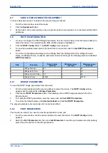
To check what devices are connected to the device being monitored:
1.
From the main window, select the device.
2.
Click the
Equipment
button.
3.
At the bottom of the main window, a box shows the ports where devices are connected and their MAC
addresses.
9.7
MIRRORING FUNCTION
Port mirroring is a method of monitoring network traffic that forwards a copy of each incoming and outgoing
packet from one port of the repeater to another port where the data can be studied. Port mirroring is
managed locally and a network administrator uses it as a diagnostic tool.
To set up port mirroring:
1.
Select the address of the device in the main window.
2.
Click the Mirroring button, a new screen appears.
3.
Click the checkbox to assign a a mirror port. A mirror port copies the incoming and outgoing traffic of
the port.
9.8
PORTS ON/OFF
To enable or disable ports:
1.
Select the address of the device in the main window.
2.
Click
Ports On/Off
, a new screen appears.
3.
Click the checkbox to enable or disable a port. A disabled port has an empty checkbox.
9.9
VLAN
The Virtual Local Area Network (VLAN) is a technique used to split an interconnected physical network into
several networks. This technique can be used at all ISO/OSI levels. The VLAN switch is mainly at OSI level 1
(physical VLAN) which allows communication only between some Ethernet physical ports.
Ports on the switch can be grouped into Physical VLANs to limit traffic flooding. This is because it is limited to
ports belonging to that VLAN and not to other ports.
Port-based VLANs are VLANs where the packet forwarding decision is based on the destination MAC
address and its associated port. You must define outgoing ports allowed for each port when using port-
based VLANs. The VLAN only governs the outgoing traffic so is unidirectional. Therefore, if you wish to allow
two subscriber ports to talk to each other, you must define the egress port for both ports. An egress port is
an outgoing port, through which a data packet leaves.
To assign a physical VLAN to a set of ports:
1.
Select the address of the device in the main window.
2.
Click the
VLAN
button, a new screen appears.
3.
Use the checkboxes to select which ports will be in the same VLAN. By default all the ports share the
same VLAN.
MiCOM P747
Chapter 8 - Redundant Ethernet
P747-TM-EN-1
271
P747-TM-EN-1.1
Summary of Contents for MiCOM P747 Agile
Page 2: ......
Page 16: ...Contents MiCOM P747 xiv P747 TM EN 1 P747 TM EN 1 1...
Page 20: ...Table of Figures MiCOM P747 xviii P747 TM EN 1 P747 TM EN 1 1...
Page 21: ...INTRODUCTION CHAPTER 1...
Page 22: ...Chapter 1 Introduction MiCOM P747 2 P747 TM EN 1 P747 TM EN 1 1...
Page 31: ...SAFETY INFORMATION CHAPTER 2...
Page 32: ...Chapter 2 Safety Information MiCOM P747 12 P747 TM EN 1 P747 TM EN 1 1...
Page 42: ...Chapter 2 Safety Information MiCOM P747 22 P747 TM EN 1 P747 TM EN 1 1...
Page 43: ...HARDWARE DESIGN CHAPTER 3...
Page 44: ...Chapter 3 Hardware Design MiCOM P747 24 P747 TM EN 1 P747 TM EN 1 1...
Page 74: ...Chapter 3 Hardware Design MiCOM P747 54 P747 TM EN 1 P747 TM EN 1 1...
Page 75: ...CONFIGURATION CHAPTER 4...
Page 76: ...Chapter 4 Configuration MiCOM P747 56 P747 TM EN 1 P747 TM EN 1 1...
Page 117: ...PROTECTION FUNCTIONS CHAPTER 5...
Page 118: ...Chapter 5 Protection Functions MiCOM P747 98 P747 TM EN 1 P747 TM EN 1 1...
Page 160: ...Chapter 5 Protection Functions MiCOM P747 140 P747 TM EN 1 P747 TM EN 1 1...
Page 161: ...MONITORING AND CONTROL CHAPTER 6...
Page 162: ...Chapter 6 Monitoring and Control MiCOM P747 142 P747 TM EN 1 P747 TM EN 1 1...
Page 211: ...SCADA COMMUNICATIONS CHAPTER 7...
Page 212: ...Chapter 7 SCADA Communications MiCOM P747 192 P747 TM EN 1 P747 TM EN 1 1...
Page 259: ...REDUNDANT ETHERNET CHAPTER 8...
Page 260: ...Chapter 8 Redundant Ethernet MiCOM P747 240 P747 TM EN 1 P747 TM EN 1 1...
Page 293: ...CYBER SECURITY CHAPTER 9...
Page 294: ...Chapter 9 Cyber Security MiCOM P747 274 P747 TM EN 1 P747 TM EN 1 1...
Page 313: ...SETTINGS APPLICATION SOFTWARE CHAPTER 10...
Page 314: ...Chapter 10 Settings Application Software MiCOM P747 294 P747 TM EN 1 P747 TM EN 1 1...
Page 322: ...Chapter 10 Settings Application Software MiCOM P747 302 P747 TM EN 1 P747 TM EN 1 1...
Page 323: ...BUSBAR COMMISSIONING TOOL CHAPTER 11...
Page 324: ...Chapter 11 Busbar Commissioning Tool MiCOM P747 304 P747 TM EN 1 P747 TM EN 1 1...
Page 330: ...Chapter 11 Busbar Commissioning Tool MiCOM P747 310 P747 TM EN 1 P747 TM EN 1 1...
Page 331: ...SCHEME LOGIC CHAPTER 12...
Page 332: ...Chapter 12 Scheme Logic MiCOM P747 312 P747 TM EN 1 P747 TM EN 1 1...
Page 348: ...Chapter 12 Scheme Logic MiCOM P747 328 P747 TM EN 1 P747 TM EN 1 1...
Page 349: ...INSTALLATION CHAPTER 13...
Page 350: ...Chapter 13 Installation MiCOM P747 330 P747 TM EN 1 P747 TM EN 1 1...
Page 361: ...COMMISSIONING INSTRUCTIONS CHAPTER 14...
Page 362: ...Chapter 14 Commissioning Instructions MiCOM P747 342 P747 TM EN 1 P747 TM EN 1 1...
Page 387: ...MAINTENANCE AND TROUBLESHOOTING CHAPTER 15...
Page 388: ...Chapter 15 Maintenance and Troubleshooting MiCOM P747 368 P747 TM EN 1 P747 TM EN 1 1...
Page 403: ...TECHNICAL SPECIFICATIONS CHAPTER 16...
Page 404: ...Chapter 16 Technical Specifications MiCOM P747 384 P747 TM EN 1 P747 TM EN 1 1...
Page 425: ...SYMBOLS AND GLOSSARY APPENDIX A...
Page 426: ...Appendix A Symbols and Glossary MiCOM P747 406 P747 TM EN 1 P747 TM EN 1 1...
Page 443: ...COMMISSIONING RECORD APPENDIX B...
Page 444: ...Appendix B Commissioning Record MiCOM P747 424 P747 TM EN 1 P747 TM EN 1 1...
Page 449: ...WIRING DIAGRAMS APPENDIX C...
Page 450: ...Appendix C Wiring Diagrams MiCOM P747 430 P747 TM EN 1 P747 TM EN 1 1...
Page 456: ...Appendix C Wiring Diagrams MiCOM P747 436 P747 TM EN 1 P747 TM EN 1 1...
Page 457: ......

