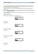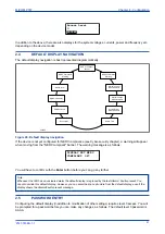
6.
Move down to the next cell (
RP1 Baud Rate
). This cell controls the baud rate to be used. Six baud
rates are supported by the IED 1200 bits/s, 2400 bits/s, 4800 bits/s, 9600 bits/s, 19200 bits/s and
38400 bits/s. Make sure that the baud rate selected on the IED is the same as that set on the master
station.
COMMUNICATIONS
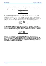
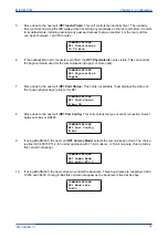
RP1 Baud rate
9600 bits/s
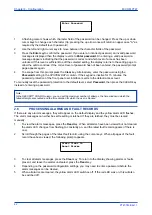
7.
Move down to the next cell (
RP1 Parity
). This cell controls the parity format used in the data frames.
The parity can be set to be one of
None
,
Odd
or
Even
. Make sure that the parity format selected on
the IED is the same as that set on the master station.
COMMUNICATIONS
RP1 Parity
None
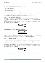
8.
Move down to the next cell (
Modbus IEC Time
). This cell controls the order in which the bytes of
information are transmitted. There is a choice of Standard or Reverse. When
Standard
is selected
the time format complies with IEC 60870-5-4 requirements such that byte 1 of the information is
transmitted first, followed by bytes 2 through to 7. If
Reverse
is selected the transmission of
information is reversed.
COMMUNICATIONS
Modbus IEC Time
Standard
3.5
IEC 61850 CONFIGURATION
You cannot configure the device for IEC 61850 using the HMI panel on the product. For this you must use
the IEC 61850 Configurator, which is part of the settings application software.
IEC 61850 allows IEDs to be directly configured from a configuration file. The IED’s system configuration
capabilities are determined from an IED Capability Description file (ICD), supplied with the product. By using
ICD files from the products to be installed, you can design, configure and test (using simulation tools), a
substation’s entire protection scheme before the products are installed into the substation.
To help with this process, the settings application software provides an IEC 61850 Configurator tool, which
allows the pre-configured IEC 61850 configuration file to be imported and transferred to the IED. As well as
this, you can manually create configuration files for all products, based on their original IED capability
description (ICD file).
Other features include:
●
The extraction of configuration data for viewing and editing.
●
A sophisticated error checking sequence to validate the configuration data before sending to the IED.
Note:
Some configuration data is available in the IEC61850 CONFIG. column, allowing read-only access to basic
configuration data.
Chapter 4 - Configuration
MiCOM P747
74
P747-TM-EN-1
P747-TM-EN-1.1
Summary of Contents for MiCOM P747 Agile
Page 2: ......
Page 16: ...Contents MiCOM P747 xiv P747 TM EN 1 P747 TM EN 1 1...
Page 20: ...Table of Figures MiCOM P747 xviii P747 TM EN 1 P747 TM EN 1 1...
Page 21: ...INTRODUCTION CHAPTER 1...
Page 22: ...Chapter 1 Introduction MiCOM P747 2 P747 TM EN 1 P747 TM EN 1 1...
Page 31: ...SAFETY INFORMATION CHAPTER 2...
Page 32: ...Chapter 2 Safety Information MiCOM P747 12 P747 TM EN 1 P747 TM EN 1 1...
Page 42: ...Chapter 2 Safety Information MiCOM P747 22 P747 TM EN 1 P747 TM EN 1 1...
Page 43: ...HARDWARE DESIGN CHAPTER 3...
Page 44: ...Chapter 3 Hardware Design MiCOM P747 24 P747 TM EN 1 P747 TM EN 1 1...
Page 74: ...Chapter 3 Hardware Design MiCOM P747 54 P747 TM EN 1 P747 TM EN 1 1...
Page 75: ...CONFIGURATION CHAPTER 4...
Page 76: ...Chapter 4 Configuration MiCOM P747 56 P747 TM EN 1 P747 TM EN 1 1...
Page 117: ...PROTECTION FUNCTIONS CHAPTER 5...
Page 118: ...Chapter 5 Protection Functions MiCOM P747 98 P747 TM EN 1 P747 TM EN 1 1...
Page 160: ...Chapter 5 Protection Functions MiCOM P747 140 P747 TM EN 1 P747 TM EN 1 1...
Page 161: ...MONITORING AND CONTROL CHAPTER 6...
Page 162: ...Chapter 6 Monitoring and Control MiCOM P747 142 P747 TM EN 1 P747 TM EN 1 1...
Page 211: ...SCADA COMMUNICATIONS CHAPTER 7...
Page 212: ...Chapter 7 SCADA Communications MiCOM P747 192 P747 TM EN 1 P747 TM EN 1 1...
Page 259: ...REDUNDANT ETHERNET CHAPTER 8...
Page 260: ...Chapter 8 Redundant Ethernet MiCOM P747 240 P747 TM EN 1 P747 TM EN 1 1...
Page 293: ...CYBER SECURITY CHAPTER 9...
Page 294: ...Chapter 9 Cyber Security MiCOM P747 274 P747 TM EN 1 P747 TM EN 1 1...
Page 313: ...SETTINGS APPLICATION SOFTWARE CHAPTER 10...
Page 314: ...Chapter 10 Settings Application Software MiCOM P747 294 P747 TM EN 1 P747 TM EN 1 1...
Page 322: ...Chapter 10 Settings Application Software MiCOM P747 302 P747 TM EN 1 P747 TM EN 1 1...
Page 323: ...BUSBAR COMMISSIONING TOOL CHAPTER 11...
Page 324: ...Chapter 11 Busbar Commissioning Tool MiCOM P747 304 P747 TM EN 1 P747 TM EN 1 1...
Page 330: ...Chapter 11 Busbar Commissioning Tool MiCOM P747 310 P747 TM EN 1 P747 TM EN 1 1...
Page 331: ...SCHEME LOGIC CHAPTER 12...
Page 332: ...Chapter 12 Scheme Logic MiCOM P747 312 P747 TM EN 1 P747 TM EN 1 1...
Page 348: ...Chapter 12 Scheme Logic MiCOM P747 328 P747 TM EN 1 P747 TM EN 1 1...
Page 349: ...INSTALLATION CHAPTER 13...
Page 350: ...Chapter 13 Installation MiCOM P747 330 P747 TM EN 1 P747 TM EN 1 1...
Page 361: ...COMMISSIONING INSTRUCTIONS CHAPTER 14...
Page 362: ...Chapter 14 Commissioning Instructions MiCOM P747 342 P747 TM EN 1 P747 TM EN 1 1...
Page 387: ...MAINTENANCE AND TROUBLESHOOTING CHAPTER 15...
Page 388: ...Chapter 15 Maintenance and Troubleshooting MiCOM P747 368 P747 TM EN 1 P747 TM EN 1 1...
Page 403: ...TECHNICAL SPECIFICATIONS CHAPTER 16...
Page 404: ...Chapter 16 Technical Specifications MiCOM P747 384 P747 TM EN 1 P747 TM EN 1 1...
Page 425: ...SYMBOLS AND GLOSSARY APPENDIX A...
Page 426: ...Appendix A Symbols and Glossary MiCOM P747 406 P747 TM EN 1 P747 TM EN 1 1...
Page 443: ...COMMISSIONING RECORD APPENDIX B...
Page 444: ...Appendix B Commissioning Record MiCOM P747 424 P747 TM EN 1 P747 TM EN 1 1...
Page 449: ...WIRING DIAGRAMS APPENDIX C...
Page 450: ...Appendix C Wiring Diagrams MiCOM P747 430 P747 TM EN 1 P747 TM EN 1 1...
Page 456: ...Appendix C Wiring Diagrams MiCOM P747 436 P747 TM EN 1 P747 TM EN 1 1...
Page 457: ......

