MobileView User Manual
3 DVR Installation and Wiring
1036564B / October 2002
19
3.2 W
IRING THE
DVR
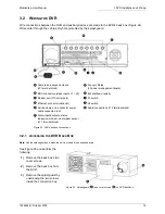
Wire connections between the DVR and auxiliary devices are made to the DVR’s back box (Figure 24).
Wires enter through the cable-entry hole protected by the splashguard.
3.2.1 A
CCESSING THE
DVR B
ACK
B
OX
Note:
Use the splashguard only when the unit is mounted in an exposed area.
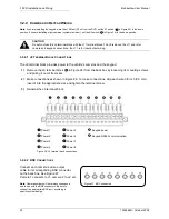
See Figure 25 and perform the
following:
1)
Remove the back box’s two
cover screws.
2)
Remove the back box from
the DVR.
3)
Remove the splashguard by
unscrewing the two screws
inside the connection box.
Camera and keypad outputs
(J9
terminal
block)
Four-pin Molex
(J3 power management board)
BNC connectors (video inputs J1 – J8)
EM shutdown resistor
Modem port (J10 serial port)
S1 switch
Ethernet connector (optional)
S2 switch
Ferrite clamp on 4-conductor power
cable connected to J3
Audio connections (J12 terminal block)
Alarm inputs/outputs, status
indication, modem, and impact sensor
(J11 terminal block)
Figure 24. DVR back box connections
Figure 25. Splashguard (
) and cover screws (
) on DVR back box
Summary of Contents for MobileView
Page 1: ...MobileView Mobile Digital Video Recorder ...
Page 42: ...42 1036564B October 2002 ...
Page 44: ...44 1036564B October 2002 ...
Page 50: ...50 1036564B October 2002 ...
Page 52: ......


