background image

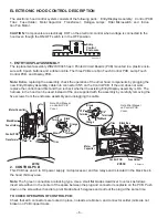
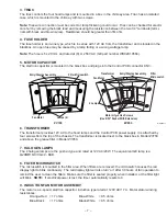
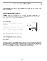
– 11 –

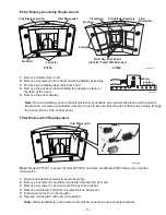
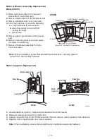
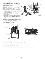
Entry/Display Assembly Replacement

1.  Remove 3 filters from hood.
2.  Remove 2 screws (A) from hood and entry/display assembly.
3.  Remove entry/display assembly from hood.
4.  Remove the pusher bracket holding the display in place on
     the face of the hood.
5.  Remove the entire display.

Note: When reinstalling, ensure that all electrical connections are securely fastened, and the pusher
bracket and 2 screws are installed correctly. Check to be sure that the push buttons move freely through
the front surface of the control panel.

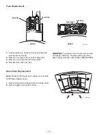
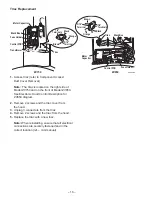
Filter Microswitch Replacement

Note: Model ZV750Y1 is shown; Model ZV750Y2 and later, and Model ZV850 have only one filter
microswitch.

1.  Disconnect electrical power to hood assembly.
2.  Remove 2 screws (A) and filter microswitch bracket (B) from fan.
3.  Remove 2 screws (C) and microswitch box from bracket.
4.  Remove microswitch (D) from microswitch box and cover.
5.  Disconnect wires from microswitch.
6.  Replace microswitch with new microswitch.

     Note: When reinstalling, ensure that all electrical connections are securely fastened.

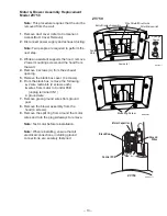
Transformer

4 Lamps

Fan Motor

Motor mtg.-4 Hex Screws

(Use 9/32" Socket With Extension) 

Entry/Display Assembly

Filter
Microswitch 

Lamps (4)

Fan Motor 

Entry/Display Assembly

Filter Microswitch

A

A

GEA00017

ZV750

ZV850

A

A

GEA00029

Filter Microswitch

A

B

D

C

GEA00015

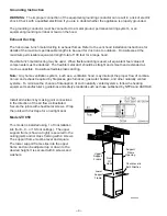
Entry
Control
Enclosure 

Summary of Contents for Monogram ZV750

Page 1: ...C PUB 31 9043 03 00 MODEL SERIES TECHNICAL SERVICE GUIDE GE Consumer Service Training Monogram Wall Mounted and Island Hoods ZV750 ZV850...

Page 2: ...d personal injury disconnect power before servicing this product If electrical power is required for diagnosis or test purposes disconnect the power immediately after performing the necessary checks R...

Page 3: ...rol PCB Replacement 10 Entry Display Assembly Replacement 11 Filter Microswitch Replacement1 11 Fuse Replacement 12 Glass Visor Replacement 12 Motor Blower Assembly Replacement 13 Motor Capacitor Repl...

Page 4: ...ings GEA00028 25 1 2 Recommended 36 Reference Height to Ceiling 8 1 4 35 3 8 27 1 2 Nomenclature Mini Manual Locator Label Nomenclature 25 1 2 Recommended 36 Min GEA00027 Mini Manual Locator Label Hei...

Page 5: ...s Electrical Supply The vent hood must be supplied with 120V 60Hz electrical power and connected to an individual properly grounded branch circuit protected by a 15 or 20 ampere circuit breaker or tim...

Page 6: ...ducting Note Any home ventilation system such as a ventilation hood may interrupt the proper flow of combus tion air and exhaust required by fireplaces gas furnaces gas water heaters and other natura...

Page 7: ...rical power to light on and off Remembers the last light level used 7 Decrease Brightness Dims lights in 6 light levels 8 Increase Brightness Brightens lights in 6 light levels Display LEDs 9 Filter C...

Page 8: ...is OK The harness in the hood can be used instead of the one supplied with the assembly by carefully removing the five screws from the enclosure assembly and unplugging the cable 2 CONTROL PCB This PC...

Page 9: ...ttached by four screws from the top of the chassis The transformer is located next to the black box in Model ZV750 and above the grease filter in Model ZV850 7 HALOGEN LAMPS The 4 halogen lamps are th...

Page 10: ...ght will alert you when 30 hours have passed Remove the grease filters and wash them either by hand or in the dishwasher using nonabrasive soap Note If electrical power is lost the timer automati call...

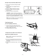
Page 11: ...ng ensure that all electrical connections are securely fastened Filter Replacement Access to lighting and wiring 1 Grasp knob and push filter back into rear recess to release front edge of filter from...

Page 12: ...te Control PCB Replacement 1 Access black box refer to Component Access Duct Cover Removal 2 Disconnect motor capacitor connection from terminal CN3 3 Disconnect entry display assembly cable from term...

Page 13: ...del ZV750Y1 is shown Model ZV750Y2 and later and Model ZV850 have only one filter microswitch 1 Disconnect electrical power to hood assembly 2 Remove 2 screws A and filter microswitch bracket B from f...

Page 14: ...r Replacement Note Model ZV750 hood has 1 glass visor and the ZV850 has 2 glass visors 1 Remove the plastic screws from the range hood 2 Remove glass visor s from hood GEA00032 Fuse Replacement WARNIN...

Page 15: ...ack box remove the following a 2 wire restraints 2 screws each b wires from motor to Control PCB unplug terminal CN1 c ground wire 7 Remove green ground wires from ground post 8 Remove the blower asse...

Page 16: ...rmer 4 Lamps Fan Motor Motor mtg 4 Hex Screws Use 9 32 Socket With Extension Entry Display Assembly Filter Microswitch Change Lamps GEA00004 Motor Capacitor Replacement 1 Access black box refer to Com...

Page 17: ...es from transformer Note Model ZV750 transformer does not have an external ground wire Model ZV850 trans former has an internal green ground wire attached to the lower ground screw 4 Remove the 2 scre...

Page 18: ...s from the triac 4 Remove 2 screws and the triac from the hood 5 Replace the triac with a new triac Note When reinstalling ensure that all electrical connections are securely fastened and in the corre...

Page 19: ...E RE SEA T RIGHT FILTER ORDER INSTALL TRIAC ORDER INSTALL TRANSFORMER ORDER INSTALL ENTRY DISPLAY ASSEMBLY CONTROL PCBs CHECK MODIFY TRIAC CONNECTIONS ORDER INSTALL CONTROL PCBs FIX ORDER MOTOR FIX WI...

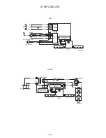
Page 20: ...CN3 WHITE FAN TOUCH PCB DISPLAY PCB LIGHT TOUCH PCB GEA00013 FILTER MICRO SWITCHES ZV750 4 LAMPS 12V AC 20W 12 5 F 250V AC MOTOR MOTOR CAPACITOR CN5 CN4A LINE 120V AC WHITE 120V FUSE BROWN 2 BLUE RED...

Page 21: ...GE BLUE RED M GEA00064 FILTER MICRO SWITCH CN4A G TO TRIAC GATE MICROPROCESSOR CIRCUIT VIOLET WHITE GEA00024 FILTER MICRO SWITCH CN4A GREY G TO TRIAC GATE MICROPROCESSOR CIRCUIT VIOLET WHITE CN3 WHITE...

Page 22: ...HITE NEUT GND LINE 120V AC CN2 EMI FILTER MICROPROCESSOR CIRCUIT FAN TOUCH PCB DISPLAY PCB LIGHT TOUCH PCB CN5 GEA00026 A1 A2 G ORANGE 12 VAC 8A250V 5X20MM TRANSFORMER ISOLATED TRIAC CN4A FUSE BROWN 2...

Page 23: ...21 Notes...

Page 24: ...22 Model ZV750 Illustrated Parts Breakdown...

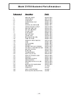
Page 25: ...ED CIRCUIT BOARD WB27X10004 170 FUSE WB02X10646 171 FUSE HOLDER WB02X10647 195 BRACKET WB02X10399 199 CERAMIC INSULATION BASE WB02X10400 200 DICHROIC LAMP PROTECTION WB08X10001 202 REFLECTOR STOP WB02...

Page 26: ...24 Model ZV850 Illustrated Parts Breakdown...

Page 27: ...9 UPPER DUCT 10 FT CEIL WB38X10033 133 IMPLEMENT HOLDER WB03X10085 166 PRINTED CIRCUIT BOARD WB27X10004 170 FUSE WB02X10646 171 FUSE HOLDER WB02X10647 195 BRACKET WB02X10399 199 CERAMIC INSULATION BAS...

Page 28: ...26 Notes...
Page 29: ...the product please contact your dealer or our Consumer Affairs office at the address below or call toll free GE Answer Center 800 626 2000 consumer information service Replacement of house fuses or re...

Page 30: ...cure feeling that GE Consumer Service will still be there after your warranty expires Purchase a GE contract while your warranty is still in effect and you ll receive a substantial discount With a mul...

Reviews: