2-16
469 Motor Management Relay
GE Power Management
2.2 ELECTRICAL
2 INSTALLATION
2
b) REDUCED RTD LEAD NUMBER APPLICATION
The 469 requires three leads to be brought back from each RTD: Hot, Return and Compensation. This can be
quite expensive. It is however possible to reduce the number of leads required to 3 for the first RTD and 1 for
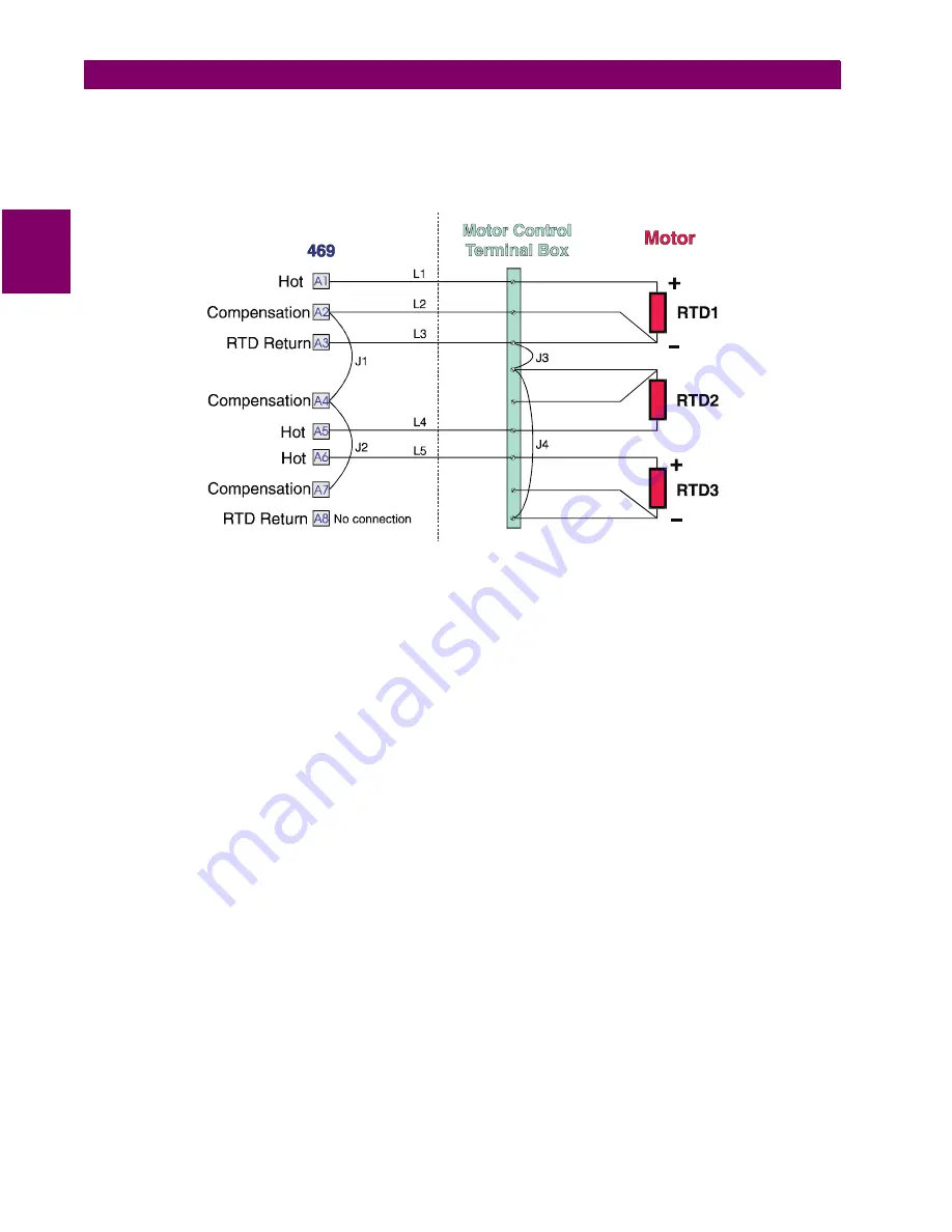
each successive RTD. Refer to the figure below for wiring configuration for this application.
Figure 2–19: REDUCED WIRING RTDS
The Hot line would have to be run as usual for each RTD. The Compensation and Return leads, however, need
only be run for the first RTD. At the motor RTD terminal box, the RTD Return leads must be jumpered together
with as short as possible jumpers. The Compensation leads must be jumpered together at the 469.
Note that an error is produced on each RTD equal to the voltage drop across the jumper on the RTD return.
This error increases with each successive RTD added.
V
RTD1
=
V
RTD1
V
RTD2
=
V
RTD2
+
V
J3
V
RTD3
= V
RTD3
+ V
J3
+ V
J4
V
RTD4
= V
RTD4
+ V
J3
+ V
J4
+ V
J5
, etc....
This error is directly dependent on the length and gauge of the wire used for the jumpers and any error intro-
duced by a poor connection. For RTD types other than 10
Ω
Copper, the error introduced by the jumpers is
negligible.
This RTD wiring technique reduces the cost of wiring, however, the following disadvantages must be noted:
1.
There will be an error in temperature readings due to lead and connection resistances. This technique is
NOT recommended for 10
Ω
Copper RTDs.
2.
If the RTD Return lead to the 469 or any of the jumpers break, all RTDs from the point of the break will read
open.
3.
If the Compensation lead or any of the jumpers break, all RTDs from the point of the break will function
without any lead compensation.


