GE Power Management
469 Motor Management Relay
4-13
4 SETPOINT PROGRAMMING
4.3 S2 SYSTEM SETUP
4
4.3.3 POWER SYSTEM
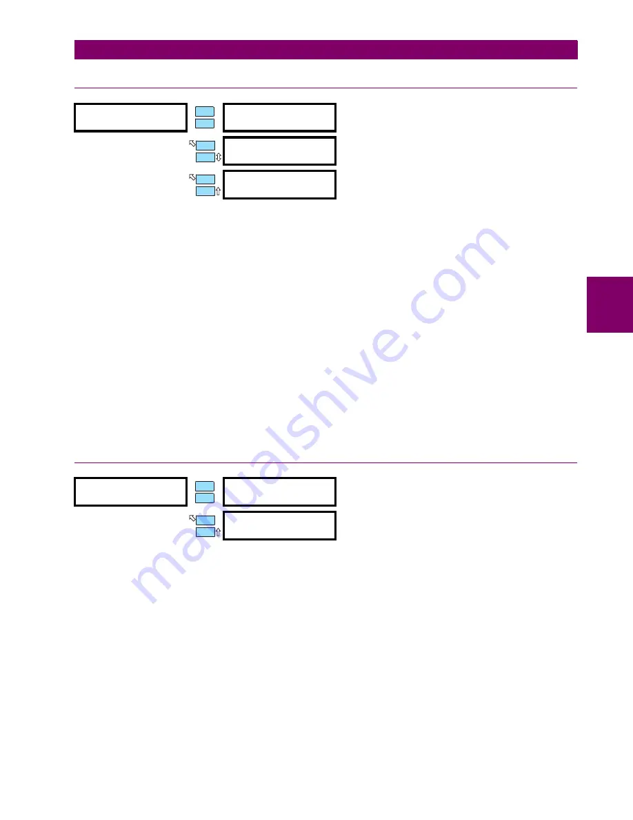
Enter the nominal system frequency here. These setpoints allow the 469 to determine the internal sampling
rate for maximum accuracy.
The 469 may be used on variable frequency drives when the
NOMINAL SYSTEM FREQUENCY
is set to
"Variable"
. All
of the elements function in the same manner with the following exceptions: the ratio of negative to positive
sequence current is calculated from 0 to 30%, not 40%, and the voltage and power elements will work properly
if the voltage waveform is approximately sinusoidal. An unfiltered voltage waveform from a pulse width modu-
lated drive cannot be measured accurately; however, the current waveform is approximately sinusoidal and
can be measured accurately. All current elements will function properly. Note, however, that undervoltage and
underfrequency elements will not work instantaneously using variable frequency. If
"Variable"
is chosen, the fil-
tering algorithm increases the trip and alarm times by up to 270 ms when the level is close to the threshold. If
the level exceeds the threshold by a significant amount, trip and alarm times will decrease until they match the
programmed delay. The exceptions to this increased time are the short circuit, ground fault, and differential ele-
ments which will trip as per specification.
If the sequence of phase rotation for a given plant is ACB rather than the standard ABC, the
SYSTEM PHASE
SEQUENCE
setpoint may be used to accommodate this. This setpoint allows the 469 to properly calculate phase
reversal, negative sequence, and power quantities. The
SPEED2 PHASE SEQUENCE
can be programmed to
accommodate the reversed motor rotation at Speed2.
4.3.4 SERIAL COMMUNICATION CONTROL
If enabled, motor starting and stopping is possible via any of the three 469 communication ports. Refer to
Chapter 6: COMMUNICATIONS for command formats. When a stop command is issued, the R1 TRIP relay is
activated for 1 second to complete the trip coil circuit for a breaker application or break the contact coil circuit
for a contactor application. When a start command is issued, the auxiliary relay assigned for starting control is
activated for 1 second to complete the close coil circuit for a breaker application or complete the start control
circuit for a contactor application. A contactor sealing contact would be used to maintain the circuit.
To issue a start or stop command via communications see Section 6.2.4: FUNCTION CODE 05: EXECUTE
OPERATION on page 6–9.
y
POWER SYSTEM
y
[ENTER] for more
NOMINAL SYSTEM
FREQUENCY: 60 Hz
Range: 50 Hz, 60 Hz, Variable
SYSTEM PHASE
SEQUENCE: ABC
Range: ABC, ACB
SPEED2 PHASE
SEQUENCE: ABC
Range:
ABC, ACB
Seen only if 2-Speed Motor Protection is enabled
y
SERIAL COM. CONTROL
y
[ENTER] for more
SERIAL COMMUNICATION
CONTROL: Off
Range: On, Off
ASSIGN START CONTROL
RELAYS: Auxiliary2
Range: Auxiliary2, Aux2 & Aux3, Auxiliary3
ENTER
ESCAPE
ð
ð
MESSAGE
ESCAPE
MESSAGE
ESCAPE
ENTER
ESCAPE
ð
ð
MESSAGE
ESCAPE


