


Major Inspection — Disassembly Procedures
Inspection and Maintenance — GEK 107048
MI-D-7
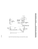
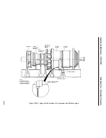
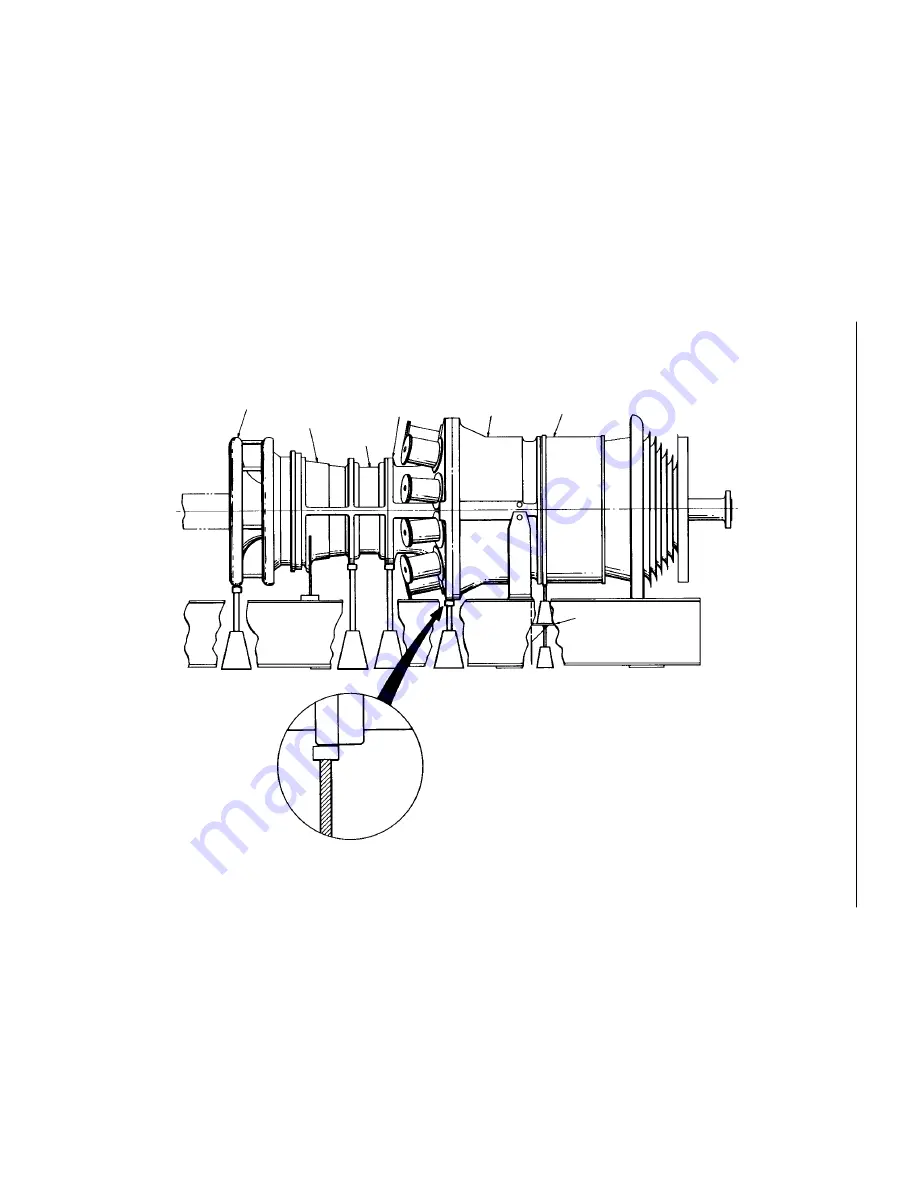
Figure MI-D.1. Support Jack Locations for Compressor and Turbine Casings.
Inlet Bell
Forward
Compressor
Casing
Aft
Compressor
Casing
Compressor
Discharge
Casing
Turbine
Casing
Exhaust
Frame
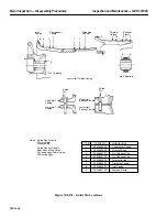
Jacking Platform
Mechanical Jacks
NO. 3
NO. 4
NO. 5
NO. 1
Turbine – Flange To Flange
Weight = 91,650 lbs.
NOTE:
Position No. 5 Is Not
Required If Compressor
Casing Ia a Single Piece
Casing (No Aft Casing).
NO. 2
Summary of Contents for MS6001B
Page 2: ...Gas Turbine Inspection and Maintenance GEK 107048 I 2 THIS PAGE INTENTIONALLY LEFT BLANK ...
Page 4: ...Inspection and Maintenance Note THIS PAGE INTENTIONALLY LEFT BLANK ...
Page 13: ...INSERT TAB INTRODUCTION ...
Page 14: ......
Page 25: ...INSERT TAB STANDARD PRACTICES ...
Page 26: ......
Page 87: ...INSERT TAB AUXILIARY CONTROLS SYSTEMS MAINTENANCE ...
Page 88: ......
Page 133: ...INSERT TAB SCHEDULED TURBINE MAINTENACE ...
Page 134: ......
Page 157: ...INSERT TAB COMBUSTION INSPECTION ...
Page 158: ......
Page 239: ...INSERT TAB HOT GAS PATH INSPECTION ...
Page 240: ......
Page 313: ...INSERT TAB MAJOR INSPECTION ...
Page 314: ......
Page 316: ...Inspection and Maintenance GEK 107048 Major Inspection 2 THIS PAGE INTENTIONALLY LEFT BLANK ...
Page 363: ...INSERT TAB MAINTENANCE FORMS ...
Page 364: ......


